
www.metabo.com Made in Germany
GA 18 LTX
GA 18 LTX G
GPA 18 LTX
GE 710 Compact
GE 710 Plus
GE 950 G Plus
GEP 710 Plus
GEP 950 G Plus
FME 737
PRC 4 en Original instructions 10

FME 737
6
10
1
2
11
B
A
6
5
5
10
7
7
1
2
GE 710 Compact
GA 18 LTX
GPA 18 LTX
GA 18 LTX G
6
7
16
14
15
13
12
11
9
8
GE 710 Plus
GEP 710 Plus
4
1
2
3
6
10
7
9
8
GE 950 G Plus
GEP 950 G Plus
1
2
4
6
10
7
9
8
5
2

3
L
max.
*2) 2014/30/EU, 2006/42/EC, 2011/65/EU
*3) EN 60745-1:2009+A11:2010, EN 60745-2-23:2013, EN 50581:2012
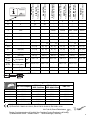
n
V
(/min)
GE 710 Compact
GE 710 Plus
GEP 710 Plus
GE 950 G Plus
GEP 950 G Plus
FME 737
1 13000 10000 2500 13000
2 18000 14000 4000 18000
3 23000 18500 5500 23000
4 27000 22000 7000 27000
5 30500 26000 8000 30500
6 34000 30500 8700 34000
* EN 60745
GA 18 LTX
*1) Serial Number 00638...
GPA 18 LTX
*1) Serial Number 00621...
GA 18 LTX G
*1) Serial Number 00639...
GE 710 Compact
*1) Serial Number 00615...
GE 710 Plus
*1) Serial Number 00616...
GEP 710 Plus
*1) Serial Number 00617..
GE 950 G Plus
*1) Serial Number 00618...
GEP 950 G Plus
*1) Serial Number 00627...
FME 737
*1) Serial Number 00737...
S-
-
-
UV 1818----
n /min 25700 6000 34000 30500 8700 34000
n
V
/min - -
13000 -
34000
10000 -
30500
2500 - 8700
13000 -
34000
n
1
/min - - 24000 24000 7200 24000
P
1
W - - 710 710 950 710
P
2
W - - 430 430 510 430
D
max
mm (in) 50 (2)
55 (2
5
/
32
) 43 (1
11
/
16
)
50 (2)
55 (2
5
/
32
)
25 (1)
T
max
mm (in)
6 (
1
/
4
)6 (
1
/
4
)6 (
1
/
4
)6 (
1
/
4
)6 (
1
/
4
)6 (
1
/
4
)
dmm (in)
6 (
1
/
4
)6 (
1
/
4
)6 (
1
/
4
)6 (
1
/
4
)6 (
1
/
4
)8 (
5
/
16
)
m kg (lbs) 2,1 (4.6) 2,2 (4.9) 1,4 (3.1) 1,6 (3.6) 1,7 (3.8) 1,4 (3.1)
L
max
mm (in) 25 (1) 25 (1) 25 (1) 25 (1) 25 (1) 25 (1)
a
h,SG
/
K
h,SG
Ø 25 mm;
U
M
=3,6 gmm;*
m/s
2
5,3 / 1,5 < 2,5 / 1,5 6,8 / 1,5 5,6 / 1,5 < 2,5 / 1,5 6,8 / 1,5
a
h,SG
/
K
h,SG
Ø 50 mm;
U
M
=14,4 gmm;*
m/s
2
13,9 / 1,5 < 2,5 / 1,5 - 16,9 / 1,5 < 2,5 / 1,5 -
L
pA
/K
pA
dB (A) 83 / 3 83 / 3 82 / 3 80 / 3 87 / 3 82 / 3
L
WA
/K
WA
dB (A) 94 / 3 94 / 3 93 / 3 91 / 3 98 / 3 93 / 3
13.
2017-06-20, Bernd Fleischmann
Direktor Produktentstehung & Qualität (Vice President Product Engineering & Quality)
*4) Metabowerke GmbH - Metabo-Allee 1 - 72622 Nuertingen, Germany

4
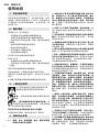
PRC 简体中文
使用说明
1. 符合标准声明
在自行承担责任的情况下,我们特此声明,这些
直磨床(按型号和序列号 *1) 标识)均符合指令
*2) 和标准 *3) 的所有相关要求。*4) 技术文档 - 请
参见第 3 页。
2. 规定用途
带有标识 G... 的工具的可:
- ... 利用磨砂点对金属进行精细研磨作业。
- ... 利用小型金属切割片进行精细切割作业。
- ... 利用立铣刀对有色金属、塑料、硬木等材料进
行镂铣。
- ...与油漆和圆形钢丝刷结合使用
- ...与抛光布轮结合使用
- ...与毛毡抛光工具结合使用
- ...与层状砂轮结合使用
该工具不适合与抛光钟结合使用。
FME 737 可...
- ... 利用磨砂点对金属进行精细研磨作业。
- ... 利用立铣刀对有色金属、塑料、硬木等材料进
行镂铣。
适用于驱动合适的麦太保挠性轴。
可针对镂铣机,扩展适当的麦太保原厂配件。
因使用不当造成的任何损坏,由用户自行承担
责任。
必须遵守通用事故预防规章和随附的安全资料。
3. 一般安全说明
为了您自身的安全及保护您的电动工具,
请特别注意标有此符号的所有文本!
警告 – 仔细阅读使用说明可降低受伤的
风险。
警告 – 请仔细阅读所有安全警告和说明。
如
果未遵守这些安全警告和说明,可能导致电
击、火灾和
/
或严重人身伤害。
保存好所有安全说明和信息资料以备查阅。
在转交电动工具时,请将这些文件一并转交。
4. 特殊安全说明
4.1 研磨、砂光、钢丝刷磨、抛光、雕刻和研磨
切断作业通用安全警告:
a) 此款电动工具旨在兼具研磨机和砂光机的功
能。带有标识 G... 的工具也可用作钢丝刷、抛光
机、雕刻机以及作为切断工具使用。仔细阅读该
电动工具附带的所有安全警告、说明、图示及规
格。不遵照以下警告和说明会导致电击、着火和/
或严重伤害。
b) FME 737 不适用于钢丝刷磨、抛光或切断。电
动工具规定用途之外的作业会招致危险并造成人
身伤害。
c) 切勿使用非工具制造商特别指定及建议使用的
配件。因为配件虽可安装在电动工具上,却不能
保证安全作业。
d) 研磨配件的额定转速须至少等于电动工具上标
注的最大转速。如果转速大于额定转速,研磨配
件会破裂飞散。
e) 配件外直径和厚度须在电动工具的额定值范围
以内。尺寸不当的配件无法得到适当的控制。
f) 砂轮、砂磨鼓轮或任何其他配件的轴尺寸必须符
合电动工具主轴或筒夹的尺寸。若安装不符合电
动工具安装零件的配件,则可能会导致不平衡、
引发剧烈振动并甚至造成失控。
g) 芯轴安装的砂轮、砂磨鼓轮、刀具或其他配件
必须完全插入到筒夹或夹头中。如果芯轴夹持部
分过短和/或超出砂轮部分过长,则安装的砂轮可
能会松动并在高速下飞出。
h) 不得使用损坏的配件。每次使用之前,应仔细
检查配件,例如:砂轮是否存在缺口和裂痕,砂
磨鼓轮是否开豁、扯破或过度磨损,钢丝刷是否
松动或钢丝是否破裂等。如果电动工具或配件坠
落,则请查看损坏情况,或者安装完好的配件。
检查、安装配件之后,请您本人和旁观者避开旋
转配件所在平面,并以最大空载转速运行电动工
具 1 分钟。通常,损坏的配件在此测试时间即会
破裂。
i) 穿着个人防护装备。根据不同的应用,可使用
面罩、护目镜或安全眼镜。也可视情况佩戴防尘
面罩、听力防护设备、隔挡磨料或工件微小碎片
的手套和车间围裙。护目设备必须能够阻隔各式
作业中形成的飞溅碎片。防尘面罩必须能够滤除
作业中产生的颗粒。长时间置身高强度噪声之中
会导致听力下降。
j) 旁观者与工作区应保持安全距离。任何人进入
工作区必须佩戴个人防护装备。工件或破损配件
的碎片飞溅,会在作业附近区域之外造成伤害。
k) 在切割配件可能触及隐藏电线或工具本身电
线的作业中,请仅通过绝缘握持面来握持电动工
具。切割配件碰到“带电”导线会使工具外露的
金属零件“带电”,从而使操作者受到电击。

5
简体中文 PRC
l) 在启动期间必须牢牢握持工具。加速到最高速
度时,电机的反力矩可能会导致工具扭曲。
m) 如果可行,使用夹钳支撑工件。使用时,切勿
一只手握持小型工件,另一只手握持工具。用夹
钳固定小型工件可以让操作者用双手控制工具。
定位销杆、管道或导管等圆形材料在切割时容易
滚动,因此可能会导致批头卡住或弹向操作者。
n) 电线应当远离旋转的配件。一旦失控,电线可
能会被割断或缠结,人手或手臂则可能卷入旋转
的配件。
o) 配件完全停止之前,切勿放下电动工具。否则
旋转的配件会抓住工具的表面,致使电动工具从
手中挣脱。
p) 在更换批头或进行任何调整之后,确保筒夹螺
母、夹头或任何其他调整装置均牢固拧紧。松动
的调整装置可能会意外移动,从而导致失控,而
松动的旋转组件则会被大力甩出。
q) 随身携带电动工具时,切勿运行电动工具。意
外触碰旋转的配件,会造成衣物缠结,而配件则
随之被牵拉从而伤及您的身体。
r) 定期清理电动工具的通风口。电机风扇会将粉尘
吸入机壳,而过多金属粉末沉积会引发电气危险。
s) 切勿在可燃物附近操作电动工具。火花会引燃
这些物质。
t) 切勿使用需要液体冷却剂的配件。使用水或其它
液体冷却剂,可能会导致触电或点击事故的发生。
4.2 反弹和相关警告
反弹是因为旋转砂轮、砂圈、钢丝刷或任何其他
附件卡住或缠结而突发的反作用。卡住或缠结致
使旋转配件迅速停止,随之使得失控的电动工具
受到来自配件旋转反方向上的力。
例如,砂轮被工件缠结或卡住,卡住点上的砂轮
边沿会切入物料表面,致使砂轮脱出或弹出。砂
轮可能弹向操作者,也可能反向弹离,这取决于
砂轮在卡住点上的运动方向。在此种情况下,砂
轮也可能破裂。
反弹是电动工具误用和∕或不正确操作工序或条
件的结果,可通过采取下列的适当预防措施加以
避免:
a) 保持紧握电动工具,并让身体和手臂处于能够
抵御反弹力的位置。如果采取的预防措施适当,
操作者即能控制反弹力。
b) 在尖角、锐边等处作业时需格外注意。避免配
件弹跳、缠结。尖角、锐边或弹跳易致使旋转配
件缠结,造成失控或反弹。
c) 不得附装带齿锯片。此类锯片会导致频繁的反
弹和失控。
d) 始终沿材料切割边缘的方向将批头进给到材料
中(与碎片抛出的方向相同)。工具以错误方向
进给将造成批头的切割边缘脱出工件并将工具拉
入此进给方向。
e) 在使用旋转锉、切断砂轮、高速刀具或碳化钨
刀具时,必须牢固固定工件。这些轮如果在刻槽
中轻微倾斜就会卡住并造成反弹力。当切断砂轮
卡住时,通常会损坏该轮自身。当旋转锉、高速
刀具或碳化钨刀具卡住时,这些工具可能会从刻
槽中弹起,从而造成工具失控。
4.3 研磨和研磨切断作业的专用安全警告:
a) 仅使用电动工具相应的推荐砂轮类型并用于推
荐的应用。例如:请勿使用切断砂轮侧面进行研
磨。研磨切断砂轮旨在用于周边磨削,施加在侧
面的作用力可能导致砂轮碎裂。
b) 对于带螺纹的砂锥和插头,仅使用未磨损的砂
轮芯轴并附装未松动的过肩法兰,且这些芯轴应
具有正确的尺寸和长度。适当的芯轴会降低破裂
的可能性。
c) 请勿“夹住”切断砂轮或施加过大压力。不得
尝试进行过深的切割。砂轮承受过大应力,会造
成负载增加,从而使砂轮在切割过程更易扭曲或
缠结,发生反弹或砂轮破裂的可能性上升。
d) 请勿将手直对旋转的砂轮,也不要站立于其后。
当把砂轮从操作者手边的操作点移开时,可能发
生的反弹将驱使旋转的砂轮和电动工具直接朝您
而去。
e) 每当砂轮卡住、缠结或者出于任何原因中断切
割时,应切断电动工具并握住电动工具原地不动,
直至砂轮完全停止。砂轮转动期间,切勿尝试将切
断砂轮从切口上移开,否则会产生反弹。调查并采
取校正措施消除砂轮卡住或缠结的成因。
f) 请勿在工件上重启切割操作。应让砂轮达到全
速后,再小心地重新进入切割。如果在工件上重
启电动工具,则砂轮会发生粘连、脱出或反弹。
g) 对板材或任何超大工件加以支撑,可将砂轮卡
住和反弹的危险降至最低限度。大型工件受自身
重量影响而容易下垂。必须在靠近切割线处和砂
轮两侧靠近工件边缘处的工件下方放置支承。
h) 对现有墙体或其它盲区进行“盲切割”时应格
外小心。伸出的砂轮可能割及燃气管道或水管,
电线或由此造成反弹的物体。
4.4 钢丝刷磨作业的专用安全警告:
a) 注意,即使在正常作业中钢丝刷毛也会随刷子
甩出。请勿在刷子上施加过大负载而使得钢丝承
受过大应力。钢丝刷毛能够轻易刺入轻薄衣物和/
或皮肤。

6
PRC 简体中文
b) 在使用钢丝刷之前,使其以工作速度运行至
少一分钟。在此期间,任何人员不得站在钢丝刷
前或直对钢丝刷。松动的刷毛或钢丝将在磨合期
甩出。
c) 避开旋转的钢丝刷的甩出方向。使用这类钢
丝刷时,小颗粒和细小的钢丝碎片可能会高速甩
出,从而扎入操作者的皮肤。
4.5 附加安全说明
警告 – 务必始终佩戴护目镜。
如果制造商为研磨介质配备了弹性缓冲层,请在
必要时使用。
请遵循工具或配件制造商的规格说明!保护研磨
盘免受油脂侵蚀或冲撞损坏!
遵照制造商说明,细心存放并使用研磨料。
切勿使用切割片进行粗加工作业!不得在切割片
侧面施加压力。
工件必须平放并加以固定从而防止滑动,例如,
使用夹具固定。大型工件必须加以充分支承。
仅可在电机处于静止的情况下,按下主轴锁定按
钮 (4)。(GA 18 LTX、GPA 18 LTX、GA 18 LTX G、
GE 710 Plus、GEP 710 Plus、GE 950 G Plus、
GEP 950 G Plus)
请勿用手接触旋转的工具!只能在电动工具完全
停止运转后才能去除碎片和类似物。
使用前,确保研磨介质正确安装并固定。在安全
位置以怠速运行工具 60 秒,若出现明显振动或发
现其他故障,则立即停止运行。如果出现这种情
况,检查工具以确定原因。
确保工作期间产生的火花不会对用户或其他人员
造成威胁且不会点燃易燃物质。危险区域必须使
用防火材料覆盖。保证在易于着火的区域备有灭
火器。
切勿使用损坏的、偏心的或振荡的工具。
为安全起见,作业 (5) 时应确保安装有橡胶套筒 (3)
或其他手柄。
减少粉尘暴露:
使用此电动工具时产生的部分粉尘可能包含
已知可导致癌症、过敏反应、呼吸疾病、先
天缺陷或其他生殖危害的化学物质。此类化学物
质的一些示例包括:含铅油漆的铅,砖块、水泥
及其他石材产品的结晶二氧化硅,经化学处理的
木材(如橡木或榉木等实木)的砷和铬,金属,
石棉。
暴露于此类物质的风险取决于操作者或旁观者暴
露的时长。
切勿吸入这些颗粒。
为降低对这些化学物质的暴露程度:在通风良好
的区域作业,并穿戴经认可的防护装备,例如专
为过滤微小颗粒而设计的防尘面罩等。
遵守物料、员工、应用和应用地点的相关准则(例
如,职业卫生与安全法规、废物处理规范等)。
从源头收集产生的颗粒,避免在周围环境中沉积。
使用适合特定作业的配件(参见第 10 章),从而
降低肆意侵入环境的微粒数量。
使用适当的除尘装置。
通过以下措施降低粉尘暴露程度:
- 请勿将逃逸的颗粒和排出的气流朝向自己或附近
人员,也不要将其朝向沉积的粉尘。
- 使用除尘装置和/或空气净化器。
- 确保工作区域通风良好,使用真空吸尘器保证工
作区域的清洁。吹扫会使粉尘飞散。
- 使用吸尘器或用水清洗防护服。不要吹、打或刷。
4.6 电源供电工具的特殊安全说明:
在调整、更换、维护或清洁工具前,将插头从插
座中拔出。
建议使用固定式吸尘系统。务必在上游安装一个
最大脱扣电流为 30 毫安的 RCD。RCD 关闭工
具后,必须对工具进行检查和清洁。请参见 8 节
清洁。
4.7 无线工具的特殊安全说明:
在进行任何调节、更换配件、维护或清洁之前,
必须从工具中卸下电池组。
避免电池组处于潮湿环境!
切勿将电池组暴露于明火!
请勿使用破损变形的电池组!
切勿打开电池组!
切勿触摸电池触点或将电池短路!
损坏的锂电池组可能会泄漏弱酸性可燃
液体!
如果皮肤接触到电池泄漏的液体,请立即
用大量清水冲洗。如果眼睛接触到电池泄
漏的液体,请用清水冲洗并立即就医!
工具发生故障时,请从工具在取下电池组。
锂电池组的运输:
锂电池组的运输必须遵守危险品运输的相关法律
(UN 3480 和 UN 3481)。运输锂电池组时,请
了解现行的有效规范。如有必要,请咨询货运代
理。麦太保提供经认证的包装。

7
简体中文 PRC
仅配送外壳完好、不漏液的电池组。配送过程
中,应将电池组从工具中取下。防止触点发生短
路(例如,可用胶带保护)。
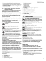
5. 概述
请参见第 2 页。
1 筒夹夹头
2 筒夹夹头螺母
3 橡胶套筒 *
4 主轴锁定按钮*
5 附加手柄 *
6 滑动开关 *
7 主手柄
8 防启动锁*
9 触发开关*
10 速度调整设定轮 *
11 粉尘过滤器 *
12 电子信号指示器 *
13 电池组卸装按钮 *
14 电池容量指示灯按钮 *
15 电池容量及信号指示灯 *
16 电池组 *
*依设备不同而异
6. 调试
6.1 仅针对电源供电工具
在接上电源前,请查看额定主电压及主频率
(标明在额定值标签上)是否与供应电源相符。
务必在上游安装一个最大脱扣电流为 30 毫安
的 RCD。
6.2 仅针对无线工具
粉尘过滤器
如果周围环境污染严重,请务必安装粉尘过
滤器 (11)。
安装粉尘过滤器 (11) 后,工具升温更快。电
子系统可为其提供保护,防止过热(参见第
9 节)。
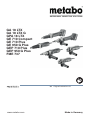
安装:请参见第 2 页,图 A。
如图所示,安装粉尘过滤器 (11)。
拆除:握住粉尘过滤器 (11) 上边沿,稍稍提起,
然后向下拖动拆除。
转动电池组
请参见第 2 页中的插图 B。
工具尾部可分 3 个阶段转动 270°,从而使得工具
的外形能够很好地适用工作条件。只有工具处于
接合位置时才能运行。
电池组
使用之前请给电池组 (16) 充电。
如性能减退,请给电池组重新充电。
理想的存储温度为 10°C 到 30°C。
“Li-Power”锂电池组容量及信号显示 (15):
- 按下 (14) 按钮,LED 将显示电量水平。
- 如果一个 LED 闪烁,则表明电池组的电力几乎
已耗完,必须重新充电。
卸下和插入电池组
拆除:按下电池组释放按钮 (13) 并向下抽出电池
组 (16)。
插入:滑入电池组 (16),直至卡合到位。
7. 使用
7.1 筒夹夹头
钻杆直径必须与筒夹夹头 (1) 的筒夹孔完全
一致!
可为不同的钻杆直径提供多种筒夹夹头。请参
见“配件”部分。
7.2 安装工具
进行任何改动之前,卸下工具的电池组并从
插座中拔下电源插头。工具必须切断,主轴
必须静止。
仅使用适合工具空载转速的工具。请参见“技
术规格”。
钻杆直径必须与筒夹夹头 (1) 的筒夹孔完全
一致!
对于磨砂点,切勿超过制造商 l
0
规定的最大
开孔钻杆长度。
l
o
允许的最大钻杆长度为 l
0
与最大插入深度 L
max
之和
(请参见第 13 章。)
将工具(整个钻杆的长度)插入到筒夹夹头 (1)。
使主轴处于静止状态。对于 GE 710 Compact、
FME 737,使用为此提供的 13 mm 扳手。对于 GA
18 LTX、GPA 18 LTX、GA 18 LTX G、GE 710 Plus、
GEP 710 Plus、GE 950 G Plus、GEP 950 G Plus,
使用主轴锁定按钮 (4) 进行此操作。
使用 17/19-mm 扳手拧紧筒夹夹头螺母 (2)。
如果没有工具插入筒夹夹头,则可手动拧紧
筒夹夹头而不必使用扳手。

8
PRC 简体中文
7.3 接通和切断
首先接通工具,然后将配件移向工件。
避免意外启动:从主插座拔下插头或停电
时,务必关闭工具。
连续工作期间,如过电动工具脱手,它会继
续运转。因此,双手必须始终握住工具的手
柄 (3)、(5)、(7),在安全位置站稳并专心工作。
避免工具打转或吸入灰尘和碎片。一旦接通
工具,只有在电机停止后才能放下工具。
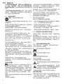
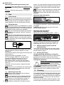
配备滑动开关的工具:
0
I
6
接通:向前推移滑动开关 (6)。如需持续运行,则
向下斜压,直至其卡合到位。
切断:按下滑动开关 (6) 后端,然后松开。
配有滑动开关的工具
(具有安全功能):
(带有 GEP...、GPA... 标识的工具)
0
I
9 8
接通:按箭头方向滑动防启动锁 (8) 并按下触发开
关 (9)。切断:松开触发开关。(9)
7.4 调整速度(仅电源供电工具)
速度为无级变速,可使用设置轮 (10) 进行预设置。
对于速度列表,请参见第 3 页的表格。
7.5 作业方向
研磨、磨砂、抛光或使用钢丝刷:轻轻地平稳按
压工具并将其从表面一侧移动到另一侧。
镂铣:轻轻地平稳按压工具。
切断作业:
切断作业方向应始终与砂轮转动方向
相反(如图)。否则将会面临危险:
工具失控并从切口处反弹。以适于工
件的速度平稳均匀地移动工具。切勿
倾斜、用力过猛或左右摇摆。
8. 清洁
在作业期间,电动工具内部可能会沉积颗粒。这
会影响电动工具的冷却。导线堆积可能会损坏电
动工具的绝缘保护套,导致电气危险。
电动工具应定期清洁,经常使用真空清洁器或通
过吹入干燥空气,对所有前后通风口进行彻底清
洁。在进行此作业之前,断开电动工具电源并带
上护目镜和防尘面罩。
9. 故障排除
9.1 电源供电工具:
- 过载保护:负载速度显著降低。电机温度过高!
允许工具以怠速运行直至冷却。
- 过载保护:负载速度略微降低。工具过载。在继
续工作之前降低负载。
- 麦太保 S 型自动安全关闭:工具自动切断。如果
电流太高(如工具突然发生卡死或反弹),则工
具将切断。使用滑动开关 (6) 关闭工具。再次接
通,即可继续如常作业。尽量防止工具卡死。请
参见 4.2 节。
- 重启保护:电动工具无法启动。重启保护功能激
活。如果在工具启动的情况下插入电源插头,或
电源在中断后恢复,则工具不会重启。请切断工
具并再次启动。
9.2 无线工具:
- 电信号指示灯 (12) 亮起,且负载速度下降。温
度过高!空转运行工具直至电信号指示灯熄灭。
- 电信号指示灯 (12) 闪烁,且工具无法启动。重
启保护功能激活。如果在工具处于“启动”位置
时放入电池组,则工具不会启动。请切断工具并
再次启动。
10. 配件
仅可使用麦太保原厂电池组和配件。
仅可使用符合使用说明中所列要求及规格的配件。
牢固地安装配件。使用支架作业时要固定好电
钻。电动工具失控可能造成人身伤害。
A 筒夹夹头(包括螺母)
Ø 3 mm = 6.31947
Ø 1/8“ = 6.31948
Ø 6 mm = 6.31945
Ø 1/4“ = 6.31949
Ø 8 mm = 6.31946
B 夹架 6.27354,用于在使用挠性轴进行作业时
进行夹持(拧紧夹紧螺钉),包括:
C 夹具托架 6.27107,用于安全固定工作台(夹
紧螺钉)。
D 挠性轴
E 对于 FME 737:
镂铣工具 (6.31501)
可作为镂铣机提供强化功能
F 充电器:ASC Ultra、ASC 15、ASC 30 和其他。

9
简体中文 PRC
G 电池组:5.2 Ah (6.25592);4.0 Ah (6.25591);
3.0 Ah (6.25594)
有关完整配件列表,请参见 www.metabo.com 或
产品目录。
11. 维修
只能由合格的电工修理电动工具!
如果需要维修麦太保电动工具,请联系当地麦太
保代表。请访问 www.metabo.com 获取地址。
可以从 www.metabo.com 下载备件列表。
12. 环境保护
生成的研磨粉尘可能包含有害物质。适当处置。
有关废弃的工具、包装和配件的环保性处置及回
收,请遵循国家相关规定。
仅适用于欧盟国家/地区:不得将电动工具
与生活垃圾一同处置!根据有关废旧电子和
电气设备的欧盟指令 2002/96/EC 及其在国
家法律中的实施方案,废旧的电动工具必须单独
收集和上交,从而以环保的方式回收。
有关无线工具的特殊说明:电池组不可按常规废
物处置。请将故障或废旧电池组送还给您的麦太
保经销商!
勿使电池组与水接触!
在处置前,请用尽电动工具电池组中的电力。防
止触点发生短路(例如,可用胶带保护)。
13. 技术规格
规格说明详见第 3 页。保留因技术发展而进行变更
的权利。
U = 电池组电压
S = 用于简单工具切换的主轴锁定
n = 空载转速(最大转速)
n
V
= 空载转速(可调整)
n
1
* = 负载速度
P
1
= 额定输入功率
P
2
= 输出功率
D
max
= 最大砂磨盘直径
T
max
= 最大黏合研磨盘厚度
d = 筒夹夹头的筒夹孔
m = 具有最小电池组的重量/无电线的重量
L
max
= 最大插入深度
测量值依照 EN 60745 确定。
防护等级为 II 级的工具
~ 交流
直流
引用的技术资料皆含有公差值在内(依照相关有
效标准)。
排放值
这些值可用来评估电动工具的排放量,以
及比较不同的电动工具。作业条件以及电动工具
或配件的状况各不相同,实际负载也随之或高或
低。当载荷较低,无法进行评估时,请让工具休
息一下。根据调整后的估计值,为使用者安排保
护措施,例如组织措施。
振动总值(三个方向的矢量和)依据 EN 60745
确定:
a
h, SG
= 振动排放值
K
h,SG
= 不确定性(振动)
U
M
= 不平衡
典型 A 荷重声音等级:
L
pA
= 声压等级
L
WA
= 声压功率等级
K
pA,
K
WA
= 不确定性
操作过程中,噪音水平可能超过 80 dB(A)。
佩戴护耳器!
问题、故障:
在个别情况下,如果工具暴露在极端外部电磁干
扰下,可能会出现速度波动或电子重启保护可能
会作出响应。在这种情况下,请切断工具并再次
启动。

ENGLISHen
10
Original instructions
Under our sole responsibility, we hereby declare
that these straight grinders, identified by type and
serial number *1), comply with all relevant
requirements of the directives *2) and standards
*3). technical documents for *4) - see Page 3.
Machines with the designation G... are designed:
- ... for fine grinding work with abrasive points on
metal.
- ... for fine cutting work with small cutting discs on
metal.
- ... for routing with end mill cutters on non-ferrous
metals, plastics, hardwood, etc.
- ...for working with paint and round wire brushes
- ...for working with polishing bobs
- ...for working with felt polishing tools
- ...for working with lamellar grinding wheels
The machine is not suitable for working with
polishing bells.
The FME 737 is designed...
- ... for fine grinding work with abrasive points on
metal.
- ... for routing with end mill cutters on non-ferrous
metals, plastics, hardwood, etc.
Suitable for driving an appropriate Metabo flexible
shaft.
Can be expanded with the appropriate original
Metabo accessories for the router.
The user bears sole responsibility for any damage
caused by inappropriate use.
Generally accepted accident prevention
regulations and the enclosed safety information
must be observed.
For your own protection and for the
protection of your power tool, pay
attention to all parts of the text that are
marked with this symbol!
WARNING – Reading the operating
instructions will reduce the risk of injury.
WARNING Read all safety warnings and
instructions. Failure to follow all safety
warnings and instructions may result in electric
shock, fire and/or serious injury.
Keep all safety instructions and information for
future reference.
Pass on your power tool only together
with these documents.
4.1 Safety warnings common for grinding,
sanding, wire brushing, polishing,
carving or abrasive cutting-off
operations:
a) This power tool is intended to
function as a
grinder and sander. Tools with the designation
G... may also be used as wire brushes,
polishers, carving and as a cut-off tool. Read all
safety warnings, instructions, illustrations and
specifications provided with this power tool.
Failure to follow all instructions listed below may
result in electric shock, fire and/or serious injury.
b) The FME 737 is not suitable for wire
brushing, polishing or cutting-off. Operations for
which the power tool was not designed may create
a hazard and cause personal injury.
c)
Do not use accessories which are not
speci
fically designed and recommended by the
tool manufacturer. Just because the accessory
can be attached to your power tool, it does not
assure safe operation.
d) The rated speed of the grinding accessories
must be at least equal to the maximum speed
marked on the power tool. Grinding accessories
running faster than their rated speed can break and
fly apart.
e) The outside diameter and the thickness of
your accessory must be within the capacity
rating of your power tool. Incorrectly sized
accessories cannot be adequately controlled.
f) The arbour size of wheels, sanding drum
s or
any other accessory must properly fit the
spindle or collet of the power tool. Accessories
that do not match the mounting hardware of the
power tool will run out of balance, vibrate
excessively and may cause loss of control.
g) Mandrel Mounted Wheels, sanding drum
s,
cutters or other accessories must be fully
inserted into the collet or chuck. If the mandrel is
insufficiently held and/or the overhang of the wheel
is too long, the Mounted Wheel may become loose
and be ejected at high velocity.
h) Do not use a damaged accessory
. Before
each use inspect the accessory such as
abrasive wheels for chips and cracks, sanding
drum for cracks, tear or excess wear, wire
brush for loose or cracked wires. If power tool
or accessory is dropped, inspect for damage or
install an undamaged accessory. After
inspecting and installing an accessory,
position yourself and bystanders away from
the plane of the rotating accessory and run the
power tool at maximum no-load speed for one
minute. Damaged accessories will normally break
apart during this test time.
i) Wear personal protective eq
uipment.
Depending on application, use face shield,
safety goggles or safety glasses. As
appropriate, wear dust mask, hearing
1. Declaration of Conformity
2. Specified Use
3. General Safety Instructions
4. Special Safety Instructions

ENGLISH en
11
protectors, gloves and workshop apron
capable of stopping small abrasive or
workpiece fragments. The eye protection must be
capable of stopping flying debris generated by
various operations. The dust mask or respirator
must be capable of filtrating particles generated by
your operation. Prolonged exposure to high
intensity noise may cause hearing loss.
j) Keep bystanders a safe distance away from
work area. Anyone entering the work area must
wear personal protective equipment. Fragments
of workpiece or of a broken accessory may fly away
and cause injury beyond immediate area of
operation.
k) Hold power tool by insulated gripping
surfaces only, when performing an operation
where the cutting accessory may contact
hidden wiring or its own cord. Cutting accessory
contacting a "live" wire may make exposed metal
parts of the power tool "live" and could give the
operator an electric shock.
l) Always hold the tool firmly in your hands
during the start-up. The reaction torque of the
motor, as it accelerates to full speed, can cause the
tool to twist.
m) Use clamps to support workpiece whenever
practical. Never hold a small workpiece in one
hand and the tool in the other hand while in
use. Clamping a small workpiece allows you to use
your hands to control the tool. Round material such
as dowel rods, pipes or tubing have a tendency to
roll while being cut, and may cause the bit to bind or
jump toward you.
n) Position the cord clear of the spinning
accessory. If you lose control, the cord may be cut
or snagged and your hand or arm may be pulled into
the spinning accessory.
o) Never lay the power tool down until the
accessory has come to a complete stop. The
spinning accessory may grab the surface and pull
the power tool out of your control.
p) After changing the bits or making any
adjustments, make sure the collet nut, chuck or
any other adjusting devices are securely
tightened. Loose adjustment devices can
unexpectedly shift, causing loss of control, loose
rotating components will be violently thrown.
q) Do not run the power tool while carrying it at
your side. Accidental contact with the spinning
accessory could snag your clothing, pulling the
accessory into your body.
r) Regularly clean the power tool’s air vents.
The motor’s fan will draw dust inside the housing
and excessive accumulation of powdered metal
may cause electrical hazards.
s) Do not operate the power tool near
flammable materials. Sparks could ignite these
materials.
t) Do not use accessories that require liquid
coolants. Using water or other liquid coolants may
result in electrocution or shock.
4.2 Kickback and Related Warnings
Kickback is a sudden reaction to a pinched or
snagged rotating wheel, sanding band, brush or any
other accessory. Pinching or snagging causes rapid
stalling of the rotating accessory which in turn
causes the uncontrolled power tool to be forced in
the direction opposite of the accessory’s rotation.
For example, if an abrasive wheel is snagged or
pinched by the workpiece, the edge of the wheel
that is entering into the pinch point can dig into the
surface of the material causing the wheel to climb
out or kick out. The wheel may either jump toward or
away from the operator, depending on direction of
the wheel’s movement at the point of pinching.
Abrasive wheels may also break under these
conditions.
Kickback is the result of power tool misuse and/or
incorrect operating procedures or conditions and
can be avoided by taking proper precautions as
given below.
a) Maintain a firm grip on the power tool and
position your body and arm to allow you to
resist kickback forces. The operator can control
kickback forces, if proper precautions are taken.
b) Use special care when working corners,
sharp edges etc. Avoid bouncing and snagging
the accessory. Corners, sharp edges or bouncing
have a tendency to snag the rotating accessory and
cause loss of control or kickback.
c) Do not attach a toothed saw blade. Such
blades create frequent kickback and loss of control.
d) Always feed the bit into the material in the
same direction as the cutting edge is exiting
from the material (which is the same direction
as the chips are thrown). Feeding the tool in the
wrong direction causes the cutting edge of the bit to
climb out of the work and pull the tool in the direction
of this feed.
e) When using rotary files, cut-off wheels, high-
speed cutters or tungsten carbide cutters,
always have the work securely clamped. These
wheels will grab if they become slightly canted in the
groove, and can kickback. When a cut-off wheel
grabs, the wheel itself usually breaks. When a rotary
file, high-speed cutter or tungsten carbide cutter
grabs, it may jump from the groove and you could
lose control of the tool.
4.3 Safety warnings specific for grinding and
abrasive cutting-off operations:
a) Use only wheel types that are recommended
for your power tool and only for recommended
applications. For example: do not grind with
the side of a cut-off wheel. Abrasive cut-off
wheels are intended for peripheral grinding, side
forces applied to these wheels may cause them to
shatter.
b) For threaded abrasive cones and plugs use
only undamaged wheel mandrels with an
unrelieved shoulder flange that are of correct
size and length. Proper mandrels will reduce the
possibility of breakage.
c) Do not “jam” a cut-off wheel or apply
excessive pressure. Do not attempt to make an

ENGLISHen
12
excessive depth of cut. Overstressing the wheel
increases the loading and susceptibility to twisting
or snagging of the wheel in the cut and the
possibility of kickback or wheel breakage.
d) Do not position your
hand in line with and
behind the rotating wheel. When the wheel, at the
point of operation, is moving away from your hand,
the possible kickback may propel the spinning
wheel and the power tool directly at you.
e) When wheel is pinched, snagged or when
interrupting a cut for any reason, switch off the
power tool and hold the power tool motionless
until the wheel comes to a complete stop.
Never attempt to remove the cut-off wheel from
the cut while the wheel is in motion otherwise
kickback may occur. Investigate and take
corrective action to eliminate the cause of wheel
pinching or snagging.
f) Do not restart the cutting operation in the
workpiece. Let the wheel reach full speed and
carefully re-enter the cut. The wheel may bind,
walk up or kickback if the power tool is restarted in
the workpiece.
g) Support panels or any oversized workpi
ece
to minimize the risk of wheel pinching and
kickback. Large workpieces tend to sag under their
own weight. Supports must be placed under the
workpiece near the line of cut and near the edge of
the workpiece on both sides of the wheel.
h) Use extra caution when making a "pocke
t
cut" into existing walls or other blind areas. The
protruding wheel may cut gas or water pipes,
electrical wiring or objects that can cause kickback.
4.4 Safety warnings specific for wire
brushing operations:
a) Be aware that wire bristles are thrown by the
brush even during ordinary operation. Do not
overstress the wires by applying excessive
load to the brush. The wire bristles can easily
penetrate light clothing and/or skin.
b) Allow brushes to run at operating sp
eed for
at least one minute before using them. During
this time no one is to stand in front or in line
with the brush. Loose bristles or wires will be
discharged during the run-in time.
c) Direct the discharge of the spinning wire
brush away from you. Small particles and tiny
wire fragments may be discharged at high velocity
during the use of these brushes and may become
imbedded in your skin.
4.5 Additional Safety Instructions:
WARNING – Always wear protective
goggles.
Use elastic cushioning layers if they have been
supplied with the grinding media and if required.
Observe the specifications of the tool or accessory
manufacturer! Protect the discs from grease or
impacts!
Abrasives must be stored and handled with care in
accordance with the manufacturer's instructions.
Never use cutting discs for roughing work! Do not
apply pressure to the side of the cutting discs.
The workpiece must lay flat and be secured against
slipping, e.g. using clamps. Large workpieces must
be sufficiently supported.
Engage the spindle lock button (4) only when the
motor is at a standstill. (GA 18 LTX, GPA 18 LTX,
GA 18 LTX G, GE 710 Plus, GEP 710 Plus,
GE 950 G Plus, GEP 950 G Plus)
Keep hands away from the rotating tool! Remove
chips and similar material only with the machine at
a standstill.
Prior to use, ensure that the abrasive media is
properly fitted and secured. Run the tool in idle for
60 seconds in a safe position and stop it
im
mediately in the event of significant vibrations or
other faults are discovered. If such a situation
occurs, check the machine to determine the cause.
Ensure that sparks produced during work do not
constitute a risk to the user or others and are not
able to ignite flammable substances. Areas at risk
must be protected with flame-resistant covers.
Always keep a fire extinguisher on hand when
working in areas prone to fire risk.
Damaged, eccentric or vibrating tools must not be
used.
In the interests of safety, ensure that the rubber
sleeve (3) or additional handle is fitted while
working (5).
Reduce dust exposure:
Some dust created by using this power tool
may contain chemicals known to cause
cancer, allergic reaction, respiratory disease, birth
defects or other reproductive harm. Some
examples of these chemicals are: Lead from lead-
based paints, crystalline silica from bricks and
cement and other masonry products, Arsenic and
chromium from chemically-treated lumber, hard
wood like oak or beech, Metals, Asbestos.
The risk from these exposures depends on how
long you or bystanders are being exposed.
Do not let particles enter the body.
To reduce your exposure to these chemicals: work
in a well ventilated area, and work with approved
safety equipment, such as dust masks that are
specially designed to filter out microscopic
particles.
Observe the relevant guidelines for your material,
staff, application and place of application (e.g.
occupational health and safety regulations,
disposal).
Collect the generated particles at the source, avoid
deposits in the surrounding area.
Use suitable accessories for special work (see
chapter 10.), thus less particles enter the
environment in an uncontrolled manner.
Use a suitable extraction unit.
Reduce dust exposure with the following measures:
- Do not direct the escaping particles and the
exhaust air stream at yourself or nearby persons
or on dust deposits.
- Use an extraction unit and/or air purifiers.

ENGLISH en
13
- Ensure good ventilation of the workplace and
keep clean using a vacuum cleaner. Sweeping or
blowing stirs up dust.
- Vacuum or wash the protective clothing. Do not
blow, beat or brush.
4.6 Special safety instructions for mains
powered machines:
Pull the plug out of the socket before making any
adjustments, changing tools, maintaining or
cleaning.
Use of a fixed extractor system is recommended.
Always install an RCD with a max. trip current of 30
mA upstream. When the machine is shut down by
the RCD, it must be checked and cleaned. See
Section 8. Cleaning.
4.7 Special safety instructions for cordless
machines:
Remove the battery pack from the machine before
making any adjustments, changing tools,
maintaining or cleaning.
Protect battery packs from water and
moisture!
Do not expose battery packs to fire!
Do not use faulty or deformed battery packs!
Do not open battery packs!
Do not touch contacts or short-circuit battery packs!
A slightly acidic, flammable fluid may leak
from defective Li-ion battery packs!
If battery fluid leaks out and comes into
contact with your skin, rinse immediately
with plenty of water. If battery fluid leaks out
and comes into contact with your eyes, wash them
with clean water and seek medical attention
immediately!
If the machine is defective, remove the battery pack
from the machine.
Transport of li-ion battery packs:
The shipping of li-ion battery pack is subject to laws
related to the carriage of hazardous goods (UN
3480 and UN 3481). Inform yourself of the currently
valid specifications when shipping li-ion battery
packs. If necessary, consult your freight forwarder.
Certified packaging is available from Metabo.
Only send the battery pack if the housing is intact
and no fluid is leaking. Remove the battery pack
from the machine for sending. Prevent the contacts
from short-circuiting (e.g. by protecting them with
adhesive tape).
See page 2.
1 Collet chuck
2 Collet chuck nut
3 Rubber sleeve *
4 Spindle locking button*
5 Additional handle *
6Slide switch*
7 Main handle
8Switch-on lock*
9Trigger*
10 Setting wheel for speed adjustment *
11 Dust filter *
12 Electronic signal indicator *
13 Battery pack release button *
14 Capacity indicator button *
15 Capacity and signal indicator *
16 Battery pack*
*equipment-specific
6.1 For mains powered machines only
Before plugging in, check that the rated mains
voltage and mains frequency, as stated on the
rating label, match with your power supply.
Always install an RCD with a max. trip current
of 30 mA upstream.
6.2 For cordless machines only
Dust filter
Always fit the dust filter if the surroundings are
heavily polluted (11).
The machine heats up faster when the dust
filter is fitted (11). It is protected by the
electronics system from overheating (see Section
9.).
To attach:
see Page 2, Figure A.
Fit the dust filter (11) as shown.
To remove:
Hold the dust filter (11) by the upper
edges, raise it slightly and then pull it downwards
and remove.
Rotating battery pack
See illustration B on page 2.
The rear section of the machine can be rotated 270°
in three stages, thus allowing the machine's shape
to be adapted to the working conditions. Only
operate the machine when it is in an engaged
position.
Battery pack
Charge the battery pack before use (16).
If performance diminishes, recharge the battery
pack.
The ideal storage temperature is between 10°C and
30°C.
"Li-Power" lithium-ion battery packs have a capacity
and signal indicator (15):
- Press the (14) button, the LEDs indicate the
charge level.
- If one LED is flashing, the battery pack is almost
flat and must be recharged.
5. Overview
6. Commissioning

ENGLISHen
14
Removing and inserting the battery pack
To remove:
Press the battery pack release button
(13) and pull the battery pack (16) downwards
and
out.
To insert:
Slide the battery pack in (16) until it
engages.
7.1 Collet chucks
The tool's shank diameter must correspond
exactly to the collet bore of the collet chuck (1)!
Various collet chucks are available for different
shank diameters. See the Accessories Section.
7.2 Fitting the tools
Before carrying out any modifications, remove
the battery pack from the machine and pull the
mains plug from the socket. The machine must be
switched off and the spindle at a standstill.
Only use tools that are suited to the no-load
speed of your machine. See the Technical
Specifications.
The tool's shank diameter must correspond
exactly to the collet bore of the collet chuck (1)!
For abrasive points, you may never exceed
the maximum open shank length specified by
the manufacturer l
0
.
The maximum permitted shaft length is the sum of l
0
and the maximum insertion depth L
max
(see
chapter13.)
Insert the tool (with the full length of the shank) in the
collet chuck (1).
Bring the spindle to a standstill. For the
GE 710 Compact, FME 737, use the 13-mm
spanner provided for this purpose. For the
GA 18 LTX, GPA 18 LTX, GA 18 LTX G,
GE 710 Plus, GEP 710 Plus, GE 950 G Plus,
GEP 950 G Plus, do this using the spindle lock
button (4).
Using the 17/19-mm spanner, tighten the collet
chuck nut (2).
If there is no tool inserted in the collet chuck,
you can tighten the collet chuck manually
rather than with the spanner.
7.3 Switching On and Off
Switch on first, then guide the accessory
towards the workpiece.
Avoid inadvertent starts: always switch the
tool off when the plug is removed from the
mains socket or if there has been a power cut.
In continuous operation, the machine
continues running if it is forced out of your
hands. You must therefore always hold the machine
with both hands using the handles provided (3), (5),
(7), assume a safe stance and concentrate while
working.
Avoid the machine swirling up or taking in dust
and chips. After switching off the machine,
only place it down when the motor has come to a
standstill.
Machines with slide switch:
Switching on: Push the slide switch (6) forward.
For continuous activation, now tilt downwards until
it engages.
Switching off: Press the rear end of the slide
switch (6) and release it.
Machines with slide switch
(with dead man function):
(Machines with the designation GEP..., GPA...)
Switching on: Slide the switch-on lock (8) in the
direction of the arrow and press the trigger (9).
Switching off: Release the trigger switch. (9)
7.4 Adjusting speed (mains powered
machines only)
The speed can be preset using the setting wheel
(10) and is infinitely variable. For a list of speeds,
see the table on page 3.
7.5 Working Directions
Grinding, sanding, polishing or using wire
brushes: Press gently and evenly on the machine
and move it from side to side over the surface.
Routing: Press gently and evenly on the machine.
Cutting-off operations:
Always work against the run of the disc
(see illustration). Otherwise there is
the danger of the machine kicking
back from the cut out of control. Guide
the machine evenly at a speed
suitable for the material being processed. Do not tilt,
apply excessive force or sway from side to side.
It is possible that particles deposit inside the power
tool during operation. This impairs the cooling of
the power tool. Conductive build-up can impair the
protective insulation of the power tool and cause
electrical hazards.
The power tool should be cleaned regularly, often
and thoroughly through all front and rear air vents
7. Use
l
o
8. Cleaning
0
I
6
0
I
9 8

ENGLISH en
15
using a vacuum cleaner or by blowing in dry air.
Prior to this operation, separate the power tool from
the power source and wear protective glasses and
dust mask.
9.1 Mains powered machines:
- Overload protection: There is a MAJOR
reduction in load speed. The motor temperature
is too high! Allow the machine to run at idle speed
until it has cooled down.
- Overload protection: There is a SLIGHT
reduction in load speed. The machine is
overloaded. Reduce the load before continuing to
work.
- Metabo S-automatic safety shutdown: The
machine was SWITCHED OFF automatically. If
the slew rate of the current is too high (for
example, if the machine suddenly seizes or
kickback occurs), the machine switches off.
Switch off the machine using the slide switch (6).
Switch it on again and continue to work as normal.
Try to prevent the machine from seizing. See
Section 4.2.
- Restart protection: The machine does not
start. The restart protection is active. If the mains
plug is inserted with the machine switched on, or if
the power supply is restored following an
interruption, the machine does not start up. Switch
the machine off and on again.
9.2 Cordless machines:
- The electronic signal display (12) lights up
and the load speed decreases. The
temperature is too high! Run the machine in idling
until the electronics signal indicator switches off.
- The electronic signal display (12) flashes and
the machine does not start. The restart
protection is active. The machine will not start if
the battery pack is inserted while the machine is
on. Switch the machine off and on again.
Only use original Metabo battery packs and Metabo
accessories.
Use only accessories which fulfil the requirements
and specifications listed in these operating
instructions.
Fit accessories securely. Secure the machine if it is
operated in a bracket. Loss of control may cause
personal injury.
A Collect chucks (including nut)
Ø 3 mm = 6.31947
Ø 1/8“ = 6.31948
Ø 6 mm = 6.31945
Ø 1/4“ = 6.31949
Ø 8 mm = 6.31946
B Clamping frame 6.27354 for clamping during
work with flexible shafts (tighten clamping
screw), including:
C Clamping bracket 6.27107 for safe securing to
the work bench (tighten clamping screw).
D Flexible shafts
E For FME 737:
Routing tool (6.31501)
For enhancement as a router
F Battery chargers: ASC Ultra, ASC 15, ASC 30
and others.
G Battery packs: 5.2 Ah (6.25592); 4.0 Ah
(6.25591); 3.0 Ah (6.25594)
For a complete range of accessories, see
www.metabo.com or the catalogue.
Repairs to electrical tools must be carried out
by qualified electricians ONLY!
Contact your local Metabo representative if you
have Metabo power tools requiring repairs. For
addresses see www.metabo.com.
You can download a list of spare parts from
www.metabo.com.
The generated grinding dust may contain harmful
substances. Dispose appropriately.
Observe national regulations on environmentally
compatible disposal and on the recycling of disused
machines, packaging and accessories.
Only for EU countries: Never dispose of
power tools in your household waste! In
accordance with European Directive 2002/
96/EC on waste electrical and electronic equipment
and its implementation in national law, used elec-
trical tools must be collected separately and
handed in for environmentally compatible recycling.
Special notes regarding cordless machines:
Battery packs may not be disposed of with regular
waste. Return faulty or used battery packs to your
Metabo dealer!
Do not allow battery packs to come into contact with
water!
Before disposal, discharge the battery pack in the
power tool. Prevent the contacts from short-
circuiting (e. g. by protecting them with adhesive
tape).
Explanatory notes on the specifications on page 3.
Changes due to technological progress reserved.
U =voltage of battery pack
S =spindle lock for easy tool changes
n =no-load speed (maximum speed)
n
V
=no-load speed (adjustable)
n
1
=on-load speed
P
1
=rated input power
P
2
=power output
D
max
=max. sanding disc diameter
T
max
=max. thickness of bonded grinding discs
d =collet bore of the collet chuck
m =weight with smallest battery pack/weight
without cord
L
max
=maximum insertion depth
9. Troubleshooting
10. Accessories
11. Repairs
12. Environmental Protection
13. Technical Specifications

ENGLISHen
16
Measured values determined in conformity with
EN 60745.
Machine in protection class II
~ AC Power
Direct current
The technical specifications quoted are subject to
tolerances (in compliance with the relevant valid
standards).
Emission values
These values make it possible to assess the
emissions from the power tool and to compare
different power tools. Depending on the operating
conditions, the condition of the power tool or the
accessories, the actual load may be higher or lower.
For assessment purposes, please allow for breaks
and periods when the load is lower. Based on the
adjusted estimates, arrange protective measures
for the user e.g. organisational measures.
Vibration total value
(vector sum of three directions)
determined in accordance with EN 60745:
a
h, SG
= Vibration emission value
K
h,SG
= Uncertainty (vibration)
U
M
=Unbalance
Typical A-effective perceived sound levels
:
L
pA
= Sound-pressure level
L
WA
=Acoustic power level
K
pA
, K
WA
= Uncertainty
During operation the noise level can exceed
80 dB(A).
Wear ear protectors!
Problems, faults:
In individual cases, the speed may fluctuate
temporarily if the machine is exposed to extreme
external electromagnetic disturbances or the
electronic restart protection may respond. In this
case, switch the machine off and on again.


Metabowerke GmbH
Metabo-Allee 1
72622 Nuertingen
Germany
www.metabo.com
170 27 1320 - 0419
-
 1
1
-
 2
2
-
 3
3
-
 4
4
-
 5
5
-
 6
6
-
 7
7
-
 8
8
-
 9
9
-
 10
10
-
 11
11
-
 12
12
-
 13
13
-
 14
14
-
 15
15
-
 16
16
-
 17
17
-
 18
18
-
 19
19
-
 20
20


他の言語で
関連論文
その他のドキュメント
-
Milwaukee C12 RT ユーザーマニュアル
-
Stanley STEL861 ユーザーマニュアル
-
-
Hikoki GP 3V Electronic Hand Grinder ユーザーマニュアル
-
Bosch Power Tools GmbH 5000 ユーザーマニュアル
-
Bosch GPO 950 ユーザーマニュアル
-
Bosch GOF 130 Professional Corded Electric Router ユーザーマニュアル
-
Hilti PS 35 取扱説明書
-
Milwaukee HD 18 HIW ユーザーマニュアル
-
Bosch GRG 18V-16 C Professional ユーザーマニュアル