
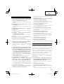
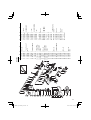
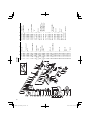
G18SE3
G 18SE3
•
G 18SG2
G 23SC3
•
G 23SE2
Handling Instructions
Instrucciones de manejo
취급 설명서
Disc Grinder
Amoladora angular
디스크그라인더
Máy mài góc
Hướng dẫn sử dụng
คูมือการใชงาน
Read through carefully and understand these instructions before use.
Leer cuidadosamente y comprender estas instrucciones antes del uso.
본 설명서를 자세히 읽고 내용을 숙지한 뒤 제품을 사용하십시오.
Đọc kỹ và hiểu rõ các hướng dẫn này trước khi sử dụng.
โปรดอานโดยละเอียดและทําความเขาใจกอนใชงาน

2
31
2
4
5
15° – 30°
AB
1
3
4
2
6
7
5
0
9
8
!
a
22.5 mm
7
9
@
#
$
)
&
*
(
)
a
q
61 6.5 mm
w
89 8.5 mm
%
^
q
w
e
r

3
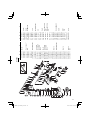
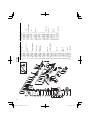
English Español
한국어
1
Brush cover Cubierta de la escobilla
브러시 커버
2
Socket for side handle Rosca para el asa lateral
사이드 핸들용 소켓
3
Push button (Spindle lock)
Botón pulsador
(bloqueo del eje)
푸시 버튼
(스핀들 잠금 장치)
4
Spindle Eje
스핀들
5
Across fl ats Distancia entre caras
물림부
6
Wheel guard
Cubierta protectora de
muela
숫돌 보호대
7
Wheel washer Arandela molar
숫돌 와셔
8
Depressed center wheel Muela de alisado
연삭 숫돌
9
Wheel nut Contratuerca molar
휠너트
0
Wrench Llave para tuercas
렌치
!
Diamond wheel Adiamantado
다이아몬드 숫돌
@
Side handle Asidero lateral
사이드 핸들
#
Lock button Botón de seguridad
잠금 버튼
$
Switch Conmutador
스위치
%
Lever Palanca
레버
^
Set piece Pieza de ajuste
세트 피스
&
Screw Tornillo
나사
*
Locating pin
Pasador de
posicionamiento
위치 결정 핀
(
Wear limit Límite de uso
마모 한도
)
No. of carbon brush No. de carbón de contacto
카본 브러시 번호
q
Usual carbon brush Escobilla de carbón usual
일반 카본 브러시
w
Auto-stop carbon brush
Escobilla de carbón de
parada
자동 정지 카본 브러시
e
Spring Resorte
스프링
r
Brush holder Portaescobilla
브러시 홀더

4
Tiếng Việt
ไทย
1
Nắp chổi than
2
Khe lắp tay nắm phụ
3
Nút ấn (khoá hãm trục)
()
4
Cần trục
5
Mặt phẳng ngang
6
Ốp chắn bánh mài
7
Vòng đệm bánh mài
8
Bánh mài lõm giữa
9
Khớp nối bánh mài
0
Chìa vặn đai ốc
!
Bánh mài kim cương
จานตัดกากเพชร
@
Tay nắm phụ
#
Nút khoá hãm
$
Công tắc
%
Tay gạt
^
Miếng chặn
&
Đinh ốc
*
Chốt định vị
(
Giới hạn mài mòn
)
Mã số chổi than
q
Chổi than loại thường
w
Chổi than tự ngừng
e
Lò xo
r
Giá đỡ chổi

English
5
GENERAL SAFETY RULES
WARNING!
Read all instructions
Failure to follow all instructions listed below may result in
electric shock, fi re and/or serious injury.
The term “power tool” in all of the warnings listed below
refers to your mains operated (corded) power tool or battery
operated (cordless) power tool.
SAVE THESE INSTRUCTIONS
1) Work area
a) Keep work area clean and well lit.
Cluttered and dark areas invite accidents.
b) Do not operate power tools in explosive
atmospheres, such as in the presence of
fl ammable liquids, gases or dust.
Power tools create sparks which may ignite the dust
of fumes.
c) Keep children and bystanders away while
operating a power tool.
Distractions can cause you to lose control.
2) Electrical safety
a) Power tool plugs must match the outlet.
Never modify the plug in any way.
Do not use any adapter plugs with earthed
(grounded) power tools.
Unmodifi ed plugs and matching outlets will reduce
risk of electric shock.
b) Avoid body contact with earthed or grounded
surfaces such as pipes, radiators, ranges and
refrigerators.
There is an increased risk of electric shock if your
body is earthed or grounded.
c) Do not expose power tools to rain or wet
conditions.
Water entering a power tool will increase the risk of
electric shock.
d) Do not abuse the cord. Never use the cord for
carrying, pulling or unplugging the power tool.
Keep cord away from heat, oil, sharp edges or
moving parts.
Damaged or entangled cords increase the risk of
electric shock.
e) When operating a power tool outdoors, use an
extension cord suitable for outdoor use.
Use of a cord suitable for outdoor use reduces the
risk of electric shock.
3) Personal safety
a) Stay alert, watch what you are doing and use
common sense when operating a power tool.
Do not use a power tool while you are tired
or under the infl uence of drugs, alcohol or
medication.
A moment of inattention while operating power tools
may result in serious personal injury.
b) Use safety equipment. Always wear eye
protection.
Safety equipment such as dust mask, non-skid
safety shoes, hard hat, or hearing protection used for
appropriate conditions will reduce personal injuries.
c) Avoid accidental starting. Ensure the switch is in
the off position before plugging in.
Carrying power tools with your fi nger on the switch or
plugging in power tools that have the switch on invites
accidents.
d) Remove any adjusting key or wrench before
turning the power tool on.
A wrench or a key left attached to a rotating part of the
power tool may result in personal injury.
e) Do not overreach. Keep proper footing and
balance at all times.
This enables better control of the power tool in
unexpected situations.
f) Dress properly. Do not wear loose clothing or
jewellery. Keep your hair, clothing and gloves
away from moving parts.
Loose clothes, jewellery or long hair can be caught in
moving parts.
g) If devices are provided for the connection of
dust extraction and collection facilities, ensure
these are connected and properly used.
Use of these devices can reduce dust related
hazards.
4) Power tool use and care
a) Do not force the power tool. Use the correct
power tool for your application.
The correct power tool will do the job better and safer
at the rate for which it was designed.
b) Do not use the power tool if the switch does not
turn it on and off .
Any power tool that cannot be controlled with the
switch is dangerous and must be repaired.
c) Disconnect the plug from the power source
before making any adjustments, changing
accessories, or storing power tools.
Such preventive safety measures reduce the risk of
starting the power tool accidentally.
d) Store idle power tools out of the reach of children
and do not allow persons unfamiliar with the
power tool or these instructions to operate the
power tool.
Power tools are dangerous in the hands of untrained
users.
e) Maintain power tools. Check for misalignment or
binding of moving parts, breakage of parts and
any other condition that may aff
ect the power
tools operation.
If damaged, have the power tool repaired before
use.
Many accidents are caused by poorly maintained
power tools.
f) Keep cutting tools sharp and clean.
Properly maintained cutting tools with sharp cutting
edges are less likely to bind and are easier to control.
g) Use the power tool, accessories and tool bits
etc., in accordance with these instructions and
in the manner intended for the particular type
of power tool, taking into account the working
conditions and the work to be performed.
Use of the power tool for operations diff erent from
intended could result in a hazardous situation.
5) Service
a) Have your power tool serviced by a qualifi ed
repair person using only identical replacement
parts.
This will ensure that the safety of the power tool is
maintained.
PRECAUTION
Keep children and infi rm persons away.
When not in use, tools should be stored out of reach of
children and infi rm persons.

6
English
SAFETY WARNINGS COMMON FOR GRINDING
OR ABRASIVE CUTTING-OFF OPERATIONS
a) This power tool is intended to function as a grinder
or cut-off tool. Read all safety warnings, instructions,
illustrations and specifi cations provided with this
power tool.
Failure to follow all instructions listed below may result in
electric shock, fi re and/or serious injury.
b) Operations such as sanding, wire brushing or
polishing are not recommended to be performed
with this power tool.
Operations for which the power tool was not designed
may create a hazard and cause personal injury.
c) Do not use accessories which are not specifi cally
designed and recommended by the tool
manufacturer.
Just because the accessory can be attached to your
power tool, it does not assure safe operation.
d) The rated speed of the accessory must be at least
equal to the maximum speed marked on the power
tool.
Accessories running faster than their rated speed can
break and fl y apart.
e) The outside diameter and the thickness of your
accessory must be within the capacity rating of your
power tool.
Incorrectly sized accessories cannot be adequately
guarded or controlled.
f) The arbour size of wheels, fl anges, backing pads or
any other accessory must properly fi t the spindle of
the power tool.
Accessories with arbour holes that do not match the
mounting hardware of the power tool will run out of
balance, vibrate excessively and may cause loss of
control.
g) Do not use a damaged accessory. Before each use
inspect the accessory such as abrasive wheels for
chips and cracks, backing pad for cracks, tear or
excess wear, wire brush for loose or cracked wires.
If power tool or accessory is dropped, inspect for
damage or install an undamaged accessory. After
inspecting and installing an accessory, position
yourself and bystanders away from the plane of
the rotating accessory and run the power tool at
maximum no-load speed for one minute.
Damaged accessories will normally break apart during
this test time.
h) Wear personal protective equipment. Depending
on application, use face shield, safety goggles or
safety glasses. As appropriate, wear dust mask,
hearing protectors, gloves and workshop apron
capable of stopping small abrasive or workpiece
fragments.
The eye protection must be capable of stopping fl ying
debris generated by various operations. The dust mask
or respirator must be capable of fi ltrating particles
generated by your operation. Prolonged exposure to high
intensity noise may cause hearing loss.
i) Keep bystanders a safe distance away from work
area. Anyone entering the work area must wear
personal protective equipment.
Fragments of workpiece or of a broken accessory may
fl y away and cause injury beyond immediate area of
operation.
j) Hold the power tool by insulated gripping surfaces
only, when performing an operation where the
cutting accessory may contact hidden wiring or its
own cord.
Cutting accessory contacting a “live” wire may make
exposed metal parts of the power tool “live” and could
give the operator an electric shock.
k) Position the cord clear of the spinning accessory.
If you lose control, the cord may be cut or snagged
and your hand or arm may be pulled into the spinning
accessory.
l) Never lay the power tool down until the accessory
has come to a complete stop.
The spinning accessory may grab the surface and pull
the power tool out of your control.
m) Do not run the power tool while carrying it at your
side.
Accidental contact with the spinning accessory could
snag your clothing, pulling the accessory into your body.
n) Regularly clean the power tool’s air vents.
The motor’s fan will draw the dust inside the housing and
excessive accumulation of powdered metal may cause
electrical hazards.
o) Do not operate the power tool near fl ammable
materials.
Sparks could ignite these materials.
p) Do not use accessories that require liquid coolants.
Using water or other liquid coolants may result in
electrocution or shock.
KICKBACK AND RELATED WARNINGS
Kickback is a sudden reaction to a pinched or snagged
rotating wheel, backing pad, brush or any other accessory.
Pinching or snagging causes rapid stalling of the rotating
accessory which in turn causes the uncontrolled power tool
to be forced in the direction opposite of the accessory’s
rotation at the point of the binding.
For example, if an abrasive wheel is snagged or pinched by
the workpiece, the edge of the wheel that is entering into the
pinch point can dig into the surface of the material causing
the wheel to climb out or kick out. The wheel may either jump
toward or away from the operator, depending on direction
of the wheel’s movement at the point of pinching. Abrasive
wheels may also break under these conditions.
Kickback is the result of power tool misuse and/or incorrect
operating procedures or conditions and can be avoided by
taking proper precautions as given below.
a) Maintain a fi rm grip on the power tool and position
your body and arm to allow you to resist kickback
forces. Always use auxiliary handle, if provided, for
maximum control over kickback or torque reaction
during start-up.
The operator can control torque reactions or kickback
forces, if proper precautions are taken.
b) Never place your hand near the rotating accessory.
Accessory may kickback over your hand.
c) Do not position your body in the area where power
tool will move if kickback occurs.
Kickback will propel the tool in direction opposite to the
wheel’s movement at the point of snagging.
d) Use special care when working corners, sharp
edges etc. Avoid bouncing and snagging the
accessory.
Corners, sharp edges or bouncing have a tendency to
snag the rotating accessory and cause loss of control or
kickback.
e) Do not attach a saw chain woodcarving blade or
toothed saw blade.
Such blades create frequent kickback and loss of control.

English
7
SAFETY WARNINGS SPECIFIC FOR GRINDING
AND ABRASIVE CUTTING-OFF OPERATIONS
a) Use only wheel types that are recommended for
your power tool and the specifi c guard designed for
the selected wheel.
Wheels for which the power tool was not designed
cannot be adequately guarded and are unsafe.
b) The guard must be securely attached to the power
tool and positioned for maximum safety, so the least
amount of wheel is exposed towards the operator.
The guard helps to protect the operator from broken
wheel fragments, accidental contact with wheel and
sparks that could ignite clothing.
c) Wheels must be used only for recommended
applications. For example: do not grind with the
side of cut-off wheel.
Abrasive cut-off wheels are intended for peripheral
grinding, side forces applied to these wheels may cause
them to shatter.
d) Always use undamaged wheel fl anges that are of
correct size and shape for your selected wheel.
Proper wheel fl anges support the wheel thus reducing
the possibility of wheel breakage. Flanges for cut-off
wheels may be diff erent from grinding wheel fl anges.
e) Do not use worn down wheels from larger power
tools.
Wheel intended for larger power tool is not suitable for
the higher speed of a smaller tool and may burst.
ADDITIONAL SAFETY WARNINGS SPECIFIC
FOR ABRASIVE CUTTING-OFF OPERATIONS
a) Do not “jam” the cut-off wheel or apply excessive
pressure. Do not attempt to make an excessive
depth of cut.
Overstressing the wheel increases the loading and
susceptibility to twisting or blinding of the wheel in the cut
and the possibility of kickback or wheel breakage.
b) Do not position your body in line with and behind
the rotating wheel.
When the wheel, at the point of operation, is moving
away from your body, the possible kickback may propel
the spinning wheel and the power tool directly at you.
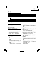
SPECIFICATIONS
Model G18SE3 G18SG2 G23SC3 G23SE2
Voltage (by areas)
*1
(110 V, 220 V, 230 V, 240 V)
Input
*1
2300 W 2500 W 2300 W 2500 W
No-load speed 8500/min 6600/min
Wheel
Outer dia 180 mm 230 mm
Inner dia 22.23 mm
Peripheral speed 80 m/s
Weight
*2
5.0 kg
*1 Be sure to check the nameplate on product as it is subject to change by areas.
*2 Weight: Only main body
c) When wheel is binding or when interrupting a cut
for any reason, switch off the power tool and hold
the power tool motionless until the wheel comes to
a complete stop. Never attempt to remove the cut-
off wheel from the cut while the wheel is in motion
otherwise kickback may occur.
Investigate and take corrective action to eliminate the
cause of wheel binding.
d) Do not restart the cutting operation in the workpiece.
Let the wheel reach full speed and carefully reenter
the cut.
The wheel may bind, walk up or kickback if the power tool
is restarted in the workpiece.
e) Support panels or any oversized workpiece to
minimize the risk of wheel pinching and kickback.
Large workpieces tend to sag under their own weight.
Supports must be placed under the workpiece near the
line of cut and near the edge of the workpiece on both
sides of the wheel.
f) Use extra caution when making a “pocket cut” into
existing walls or other blind areas.
The protruding wheel may cut gas or water pipes,
electrical wiring or objects that can cause kickback.
PRECAUTIONS ON USING DISC GRINDER
1. Never operate these power tools without Wheel Guards.
2. Check that speed marked on the wheel is equal to or
greater than the rated speed of the grinder.
Use only depressed center wheels rated at 80 m/s or
more.
3. Ensure that the wheel dimensions are compatible with
the grinder and that the wheel fi ts the spindle.
4. Abrasive wheels shall be stored and handled with care in
accordance with manufacturer’s instructions.
5. Inspect the depressed center wheel before use, do not
use chipped, cracked or otherwise defective products.
6. Always hold the body handle and side handle of the
power tool fi rmly. Otherwise the counterforce produced
may result in inaccurate and even dangerous operation.
7. Do not use cutting-off wheels for side grinding.
8. Do not use of separate reducing bushings or adapters to
adapt large hole abrasive wheels.
9. The wheel continues to rotate after the tool is switched
off .

8
English
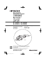
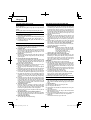
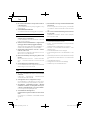
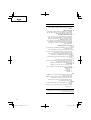
7. Confi rm the spindle lock mechanism
Confi rm that the spindle lock is disengaged by pushing
push button two or three times before switching the
power tool on (See Fig. 1).
8. Fixing the side handle
Screw the side handle into the gear cover.
PRACTICAL GRINDER APPLICATION
1. Pressure
To prolong the life of the machine and ensure a fi rst
class fi nish, it is important that the machine should not
be overloaded by applying too much pressure. In most
applications, the weight of the machine alone is suffi cient
for eff ective grinding. Too much pressure will result in
reduced rotational speed, inferior surface fi nish, and
overloading which could reduce the life of the machine.
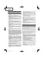
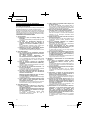
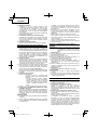
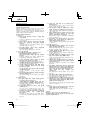
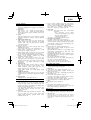
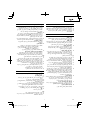
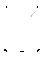
2. Grinding angle
Do not apply the entire surface of the depressed center
wheel to the material to be ground. As shown in Fig. 3,
the machine should be held at an angle of 15° – 30° so
that the external edge of the depressed center wheel
contacts the material at an optimum angle.
3. To prevent a new depressed center wheel from digging
into the workpiece, initial grinding should be performed
by drawing the grinder across the workpiece toward the
operator (Fig. 3 direction B).
Once the leading edge of the depressed center wheel is
properly abraded, grinding may be conducted in either
direction.
4. Switch operation
Switch ON: Push the locking button forward and then
press the switch lever.
* For continuous use, press the switch lever.
The switch lever is locked by pushing
the locking button forward once again.
(*Subject to change depending on area.)
Switch OFF: Press and release the switch lever.
5. Precautions immediately after fi nishing operation
After switching off the machine, do not put it down until the
depressed center wheel has come to a complete stop.
Apart from avoiding serious accidents, this precaution
will reduce the amount of dust and swarf sucked into the
machine.
CAUTIONS
○ Check that the work piece is properly supported.
○ Ensure that ventilation openings are kept clear when
working in dusty conditions.
If it should become necessary to clear dust, fi rst
disconnect the tool from the mains supply (use non-
metallic objects) and avoid damaging internal parts.
○ Ensure that sparks resulting from use do not create
a hazard e.g. do not hit persons, or ignite fl ammable
substances.
○ Always use eye and ear protection.
Other personal protective equipment such as dust
mask, gloves, helmet and apron should be worn when
necessary.
If in doubt, wear the protective equipment.
○ When the machine is not use, the power source should
be disconnected.
STANDARD ACCESSORIES
(1) Wrench ......................................................................... 1
(2) Side handle ................................................................... 1
Depressed center wheels are not provided as standard
accessories.
Standard accessories are subject to change without notice.
APPLICATIONS
○ Removal of casting fi n and fi nishing of various types of
steel, bronze and aluminum materials and castings.
○ Grinding of welded sections or sections cut by means of
a cutting torch.
○ Grinding of synthetic resins, slate, brick, marble, etc.
○ Cutting of synthetic concrete, stone, brick, marble and
similar materials.
PRIOR TO OPERATION
1. Power source
Ensure that the power source to be utilized conforms
to the power requirements specifi ed on the product
nameplate.
2. Power switch
Ensure that the power switch is in the OFF position. If
the plug is connected to a receptacle while the power
switch is in the ON position, the power tool will start
operating immediately, which could cause a serious
accident.
3. Extension cord
When the work area is removed from the power source,
use an extension cord of suffi cient thickness and rated
capacity. The extension cord should be kept as short as
practicable.
4. Fitting and adjusting the wheel guard
The wheel guard is a protective device to prevent injury
should the depressed center wheel shatter during
operation. Ensure that the guard is properly fi tted and
fastened before commencing grinding operation.
[Installing and adjusting the wheel guard]
○ Open the lever and insert the locating pin of wheel guard,
bringing it into line with the across fl ats of packing ground.
○ Then, turn the wheel guard to a desired position (for use).
○ Close the lever and fi x it. If and when required, carry out
adjustments by tightening or loosening the screw.
○ If the lever does not move smoothly, apply some
lubricating oil to the sliding section between the set piece
and the lever.
○ Fasten the wheel guard at the position where the across
fl ats of the wheel guard positioning pin and packing
ground are aligned (the position where the wheel guard
is inserted), but do not use it.
5. Ensure that the depressed center wheel to be utilized is
the correct type and free of cracks or surface defects.
Also ensure that the depressed center wheel is properly
mounted and the wheel nut is securely tightened, Refer
to the section on “ASSEMBLING AND DISASSEMBLING
THE DEPRESSED CENTER WHEEL”.
6. Conducting a trial run
Ensure that the abrasive products is correctly mounted
and tightened before use and run the tool at no-load for
30 seconds in a safe position, stop immediately if there is
considerable vibration or if other defects are detected.
If this condition occurs, check the machine to determine
the cause.

English
9
ASSEMBLING AND DISASSEMBLING THE
DEPRESSED CENTER WHEEL
CAUTION Be sure to switch OFF and disconnect the
attachment plug from the receptacle to avoid a
serious accident.
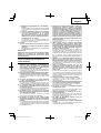
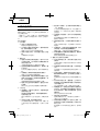
1. Assembling (Fig. 1)
(1) Turn the machine upside down so that the spindle is
facing upward.
(2) Mount the wheel washer onto the spindle.
(3) Fit the protruding part of the depressed center wheel or
diamond wheel onto the wheel washer.
(4) Screw the wheel nut onto the spindle.
(For diamond wheel assembling, use the wheel nut with
the convex side against the diamond wheel.)
(5) Insert the push button to prevent rotation of the spindle,
and tighten the wheel nut with the accessory wrench, as
shown in Fig.1.
2. Disassembling
Follow the above procedures in reverse.
CAUTION
○ Confi rm that the depressed center wheel is mounted
fi rmly.
○ Confi rm that the push button is disengaged by pushing
push button two or three times before switching the
power tool on.
MAINTENANCE AND INSPECTION
1. Inspecting the depressed center wheel
Ensure that the depressed center wheel is free of cracks
and surface defects.
2. Inspecting the mounting screws
Regularly inspect all mounting screws and ensure that
they are properly tightened. Should any of the screws
be loose, retighten them immediately. Failure to do so
could result in serious hazard.
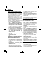
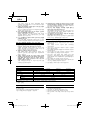
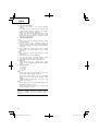
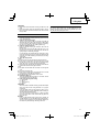
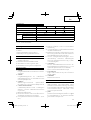
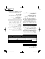
3. Inspecting the carbon brushes (Fig. 4)
The motor employs carbon brushes which are
consumable parts.
When they become worn to or near the “wear limit”, it
could result in motor trouble. When an auto-stop carbon
brush is equipped, the motor will stop automatically.
At that time, replace both carbon brushes with new ones
which have the same carbon brush numbers shown in
the fi gure. In addition, always keep carbon brushes clean
and ensure that they slide freely within the brush holders.
4. Replacing carbon brushes (Fig. 5)
<Disassembly>
(1) Loosen the D4 tapping screw retaining the brush cover
and remove the brush cover.
(2) Use the auxiliary hexagonal wrench or small screwdriver
to pull up the edge of the spring that is holding down the
carbon brush. Remove the edge of the spring toward the
outside of the brush holder.
(3) Remove the end of the pig-tail on the carbon brush from
the terminal section of brush holder and then remove the
carbon brush from the brush holder.
<Assembly>
(1) Insert the end of the pig-tail of the carbon brush in the
terminal section of brush holder.
(2) Insert the carbon brush in the brush holder.
(3) Use the auxiliary hexagonal wrench or small screwdriver
to return the edge of the spring to the head of the carbon
brush.
(4) Mount the tail cover and tighten the D4 tapping screw.
5. Maintenance of the motor
The motor unit winding is the very “heart” of the power
tool. Exercise due care to ensure the winding does not
become damaged and/or wet with oil or water.
6. Service parts list
A: Item No.
B: Code No.
C: No. Used
D: Remarks
CAUTION
Repair, modifi cation and inspection of Hitachi Power
Tools must be carried out by an Hitachi Authorized
Service Center.
This Parts List will be helpful if presented with the tool to
the Hitachi Authorized Service Center when requesting
repair or other maintenance.
In the operation and maintenance of power tools, the
safety regulations and standards prescribed in each
country must be observed.
MODIFICATIONS
Hitachi Power Tools are constantly being improved
and modifi ed to incorporate the latest technological
advancements.
Accordingly, some parts (i.e. code numbers and/or
design) may be changed without prior notice.
NOTE
Due to HITACHI’s continuing program of research and
development, the specifi cations herein are subject to
change without prior notice.

10
Español
NORMAS GENERALES DE SEGURIDAD
¡ADVERTENCIA!
Lea todas las instrucciones
Si no se siguen las instrucciones de abajo podría producirse
una descarga eléctrica, un incendio y/o daños graves.
El término “herramienta eléctrica” en todas las advertencias
indicadas a continuación hace referencia a la herramienta
eléctrica que funciona con la red de suministro (con cable) o
a la herramienta eléctrica que funciona con pilas (sin cable).
CONSERVE ESTAS INSTRUCCIONES
1) Área de trabajo
a) Mantenga la zona de trabajo limpia y bien
iluminada.
Las zonas desordenadas y oscuras pueden provocar
accidentes.
b) No utilice las herramientas eléctricas en
entornos explosivos como, por ejemplo, en
presencia de líquidos infl amables, gases o
polvo.
Las herramientas eléctricas crean chispas que
pueden hacer que el polvo desprenda humo.
c) Mantenga a los niños y transeúntes alejados
cuando utilice una herramienta eléctrica.
Las distracciones pueden hacer que pierda el control.
2) Seguridad eléctrica
a) Los enchufes de las herramientas eléctricas
tienen que ser adecuados a la toma de corriente.
No modifi que el enchufe.
No utilice enchufes adaptadores con
herramientas eléctricas conectadas a tierra.
Si no se modifi can los enchufes y se utilizan tomas
de corriente adecuadas se reducirá el riesgo de
descarga eléctrica.
b) Evite el contacto corporal con superfi cies
conectadas a tierra como tuberías, radiadores y
frigorífi cos.
Hay mayor riesgo de descarga eléctrica si su cuerpo
está en contacto con el suelo.
c) No exponga las herramientas eléctricas a la
lluvia o a la humedad.
La entrada de agua en una herramienta eléctrica
aumentará el riesgo de descarga eléctrica.
d) No utilice el cable incorrectamente. No utilice el
cable para transportar, tirar de la herramienta
eléctrica o desenchufarla.
Mantenga el cable alejado del calor, del aceite,
de bordes afi lados o piezas móviles.
Los cables dañados o enredados aumentan el riesgo
de descarga eléctrica.
e) Cuando utilice una herramienta eléctrica al aire
libre, utilice un cable prolongador adecuado
para utilizarse al aire libre.
La utilización de un cable adecuado para usarse al
aire libre reduce el riesgo de descarga eléctrica.
3) Seguridad personal
a) Esté atento, preste atención a lo que hace y
utilice el sentido común cuando utilice una
herramienta eléctrica.
No utilice una herramienta eléctrica cuando esté
cansado o esté bajo la infl uencia de drogas,
alcohol o medicación.
La distracción momentánea cuando utiliza
herramientas eléctricas puede dar lugar a
importantes daños personales.
b) Utilice equipo de seguridad. Utilice siempre una
protección ocular.
El equipo de seguridad como máscara para el
polvo, zapatos de seguridad antideslizantes, casco
o protección para oídos utilizado para condiciones
adecuadas reducirá los daños personales.
c) Evite un inicio accidental. Asegúrese de que el
interruptor está en “off ” antes de enchufarlo.
El transporte de herramientas eléctricas con el
dedo en el interruptor o el enchufe de herramientas
eléctricas con el interruptor encendido puede
provocar accidentes.
d) Retire las llaves de ajuste antes de encender la
herramienta eléctrica.
Si se deja una llave en una pieza giratoria de la
herramienta eléctrica podrían producirse daños
personales.
e) No se extralimite. Mantenga un equilibrio
adecuado en todo momento.
Esto permite un mayor control de la herramienta
eléctrica en situaciones inesperadas.
f) Vístase adecuadamente. No lleve prendas
sueltas o joyas. Mantenga el pelo, la ropa y los
guantes alejados de las piezas móviles.
La ropa suelta, las joyas y el pelo largo pueden
pillarse en las piezas móviles.
g) Si se proporcionan dispositivos para la conexión
de extracción de polvo e instalaciones de
recogida, asegúrese de que están conectados y
se utilizan adecuadamente.
La utilización de estos dispositivos puede reducir los
riesgos relacionados con el polvo.
4) Utilización y mantenimiento de las herramientas
eléctricas
a) No fuerce la herramienta eléctrica. Utilice
la herramienta eléctrica correcta para su
aplicación.
La herramienta eléctrica correcta trabajará mejor y
de forma más segura si se utiliza a la velocidad para
la que fue diseñada.
b) No utilice la herramienta eléctrica si el interruptor
no la enciende y apaga.
Las herramientas eléctricas que no pueden
controlarse con el interruptor son peligrosas y deben
repararse.
c) Desconecte el enchufe de la fuente eléctrica
antes de hacer ajustes, cambiar accesorios o
almacenar herramientas eléctricas.
Estas medidas de seguridad preventivas reducen el
riesgo de que la herramienta eléctrica se ponga en
marcha accidentalmente.
d) Guarde las herramientas eléctricas que no se
utilicen para que no las cojan los niños y no
permita que utilicen las herramientas eléctricas
personas no familiarizadas con las mismas o
con estas instrucciones.
Las herramientas eléctricas son peligrosas si son
utilizadas por usuarios sin formación.
e) Mantenimiento de las herramientas eléctricas.
Compruebe si las piezas móviles están mal
alineadas o unidas, si hay alguna pieza
rota u otra condición que pudiera afectar al
funcionamiento de las herramientas eléctricas.
Si la herramienta eléctrica está dañada, llévela a
reparar antes de utilizarla.
Se producen muchos accidentes por no realizar
un mantenimiento correcto de las herramientas
eléctricas.

Español
11
f) Mantenga las herramientas de corte afi ladas y
limpias.
Las herramientas de corte correctamente mantenidas
con los bordes de corte afi lados son más fáciles de
controlar.
g) Utilice la herramienta eléctrica, los accesorios
y las brocas de la herramienta, etc., de acuerdo
con estas instrucciones y de la manera
adecuada para el tipo de herramienta eléctrica,
teniendo en cuenta las condiciones laborales y
el trabajo que se va a realizar.
La utilización de la herramienta eléctrica para
operaciones diferentes a pretendidas podría dar
lugar a una situación peligrosa.
5) Revisión
a) Lleve su herramienta a que la revise un experto
cualifi cado que utilice sólo piezas de repuesto
idénticas.
Esto garantizará el mantenimiento de la seguridad de
la herramienta eléctrica.
PRECAUCIóN
Mantenga a los niños y a las personas enfermas alejadas.
Cuando no se utilicen, las herramientas deben
almacenarse fuera del alcance de los niños y de las
personas enfermas.
ADVERTENCIAS COMUNES DE SEGURIDAD
PARA LAS OPERACIONES DE MOLIDO O
CORTE ABRASIVO
a) Esta herarmienta eléctrica está diseñada para
utilizarse como amoladora o herramienta de
corte. Lea todas las advertencias de seguridad,
instrucciones, ilustraciones y especifi caciones
proporcionadas con esta herramienta.
Si no se siguen todas las instrucciones indicadas a
continuación, podría producirse una descarga eléctrica,
un incendio y/o daños graves.
b) No se recomienda realizar operaciones como lijado,
cepillado metálico o pulido con esta herramienta.
Las operaciones para las que no se diseñó la herramienta
eléctrica podrían producir un riesgo y causar daños
personales.
c) No utilice accesorios que no estén diseñados
y estén recomendados específi camente por el
fabricante de la herramienta.
El hecho de que el accesorio pueda acoplarse en la
herramienta eléctrica no garantiza una operación segura.
d) La velocidad nominal del accesorio debe ser al
menos igual a la velocidad máxima marcada en la
herramienta eléctrica.
Los accesorios que se utilizan con una velocidad superior
a la indicada podrían romperse o descomponerse.
e) El diámetro externo y el grosor de su accesorio
debe estar dentro de la clasifi cación de capacidad
de su herramienta metálica.
Los accesorios de tamaño incorrecto no pueden
supervisarse o controlarse adecuadamente.
f) El tamaño de pérgola de las ruedas, bridas,
almohadillas de respaldo u otros accesorios deben
encajar correctamente en el eje de la herramienta
metálica.
Los accesorios con orifi cios de pérgola que no coincidan
con la estructura de montaje de la herramienta eléctrica
se desequilibrarán, vibrarán en exceso y puden causar
una pérdida de control.
g) No utilice un accesorio dañado. Antes de cada uso,
inspeccione el accesorio, mirando si las ruedas
abrasivas tienen grietas o roturas, las almohadillas
de respaldo tienen grietas, rasgaduras o desgaste
excesivo o el cepillo metálico está suelto o con el
metal roto. Si se cae la herramienta eléctrica o el
accesorio, inspeccione si está dañado o instale un
accesorio sin dañar. Tras inspeccionar e instalar un
accesorio, tanto usted como los viandantes deben
alejarse del plano del accesorio giratorio y utilizar la
herramienta eléctrica a máxima velocidad sin carga
durante un minuto.
Los accesorios dañados se romperán durante este
periodo de prueba.
h) Utilice equipo protector personal. Dependiendo
de la aplicación, utilice protector facial, gafas
protectoras o gafas de seguridad. Si procede, utilice
máscara para polvo, protectores auditivos, guantes
y mono capaz de detener pequeños fragmentos
abrasivos o piezas de trabajo.
El protector ocular debe ser capaz de deterner los
desechos que salen desprendidos generados por
las diferentes operaciones. La máscara para polvo o
respirador debe ser capaz de fi ltrar partículas generadas
por su operación. Una exposición prolongada a un
ruido de intensidad elevada podría producir pérdida de
audición.
i) Mantenga a los viandantes alejados del área de
trabajo. Toda persona que entre en la zona de
trabajo debe utilizar equipo de protección personal.
Los fragmentos de un trabajo o un accesorio roto pueden
salir despedidos y causar daños más allá del área de
operación inmediata.
j) Sujete la herramienta eléctrica solo por las
superfi cies de agarre aisladas cuando realice una
operación en la que el accesorio de corte pueda
entrar en contacto con el cableado oculto o su
propio cable.
El hecho de que el accesorio de corte entre en contacto
con un cable con corriente podría provocar que las partes
metálicas expuestas de la herramienta eléctrica pasaran
a tener corriente, pudiendo provocar al operador una
descarga eléctrica.
k) Coloque el cable cerca del accesorio giratorio.
Si pierde el control, podría cortarse el cable o
engancharse y la mano o brazo podrían entrar en el
accesorio giratorio.
l) No coloque boca abajo la herramienta eléctrica hasta
que el accesorio se haya parado completamente.
El accesorio giratorio podría agarrar la superfi cie y
descontrolar la herramienta eléctrica.
m) No ponga en marcha la herramienta eléctrica
cuando la lleve al lado.
Un contacto accidental con el accesorio giratorio podría
enganchar la ropa y el accesorio podría herirle.
n) Limpie regularmente los conductos de aire de la
herramienta eléctrica.
El ventilador del motor sacará el polvo de dentro del
alojamiento y la acumulación excesiva de metal en polvo
podría producir peligros eléctricos.
o) No utilice la herramienta eléctrica cerca de
materiales infl amables.
Las chispas podrían quemar dichos materiales.
p) No utilice accesorios que requieran refrigerantes
líquidos.
Al utilizar agua u otros refrigerantes líquidos podría
producirse una electrocución o descarga.

12
Español
REBOTE Y ADVERTENCIAS RELACIONADAS
El rebote es una reacción repentina a una rueda giratoria,
almohadilla de soporte, cepillo u otro accesorio pinchado
o enganchado. El pinchazo o enganche causa una parada
rápida del accesorio giratorio que, a su vez, hace que la
herramienta eléctrica no controlada vaya en la dirección
opuesta del giro del accesorio en el punto de atasco.
Por ejemplo, si una rueda abrasiva es enganchada o
pinchada por la pieza de trabajo, el borde de la rueda
que entra en el punto de pinchazo puede enterrarse en la
superfi cie del material haciendo que la rueda se salga.
La rueda puede saltar hacia el operario o salir despedida
de este, dependiendo de la dirección del movimiento de
la rueda en el punto de pinchazo. Las ruedas abrasivas
también pueden romperse bajo estas condiciones.
El rebote es el resultado de un uso incorrecto y/o
procedimientos o condiciones operativos incorrectos de
la herramienta eléctrica y puede evitarse tomando las
precauciones adecuadas indicadas a continuación.
a) Agarre la herramienta eléctrica fi rmemente y
coloque el cuerpo y el brazo para que pueda
resistirse a las fuerzas de retroceso. Utilice siempre
una agarradera auxiliar, si se proporciona, para un
control máximo sobre el rebote o reacción del par
durante la puesta en marcha.
El operario puede controlar las reacciones del par o
las fuerzas de rebote, si se toman las precauciones
adecuadas.
b) No coloque la mano cerca del accesorio giratorio.
El accesorio puede rebotarse en la mano.
c) No coloque el cuerpo en la zona en la que la
herramienta eléctrica se mueva si se produce un
rebote.
El rebote impulsará a la herramienta en dirección opuesta
al movimiento de la rueda en el punto de enganche.
d) Tenga especial cuidado cuando trabaje con
esquinas, bordes afi lados, etc. Evite rebotar y
enganchar el accesorio.
Las esquinas, bordes afi lados o el rebote tienden a
enganchar el accesorio giratorio y causan la pérdida de
control y rebote.
e) No coloque una cuchilla talladora de madera o
cuchilla dentada en la sierra.
Dichas cuchillas a menudo producen rebote y pérdida de
control.
ADVERTENCIAS DE SEGURIDAD ESPECÍFICAS
PARA LAS OPERACIOENS DE MOLIDO Y
CORTE ABRASIVO
a) Utilice sólo tipos de ruedas recomendados para
su herramienta eléctrica y el protector específi co
diseñado para la rueda seleccionada.
Las ruedas para las que no se diseñó la herramienta
eléctrica no pueden protegerse adecuadamente y no
son seguras.
b) La protección debe colocarse fi rmemente en el
herramienta eléctrica y colocarse para máxima
seguridad, de forma que se expone al operario la
cantidad mínima de rueda.
La protección ayuda a proteger al operario de los
fragmentos de rueda rotos, del contacto accidental con
la rueda y de las chiscas que pueden infl amar la ropa.
c) Las ruedas deben utilizarse sólo para las
aplicaciones recomendadas. Por ejemplo, no muela
con el lado de la rueda de corte.
Las ruedas de corte abrasivas están diseñadas para un
molido periférico. Las fuerzas laterales aplicadas a estas
ruedas pueden hacer que se rompan.
d) Utilice siempre bridas de ruedas sin dañar de
tamaño y forma correcta para la rueda seleccionada.
Las bridas de rueda adecuadas soportan la rueda,
reduciendo la posibilidad de rotura de rueda. Las bridas
para ruedas de corte pueden ser diferentes de las bridas
de rueda de molido.
e) No utilice ruedas de herramientas eléctricas más
grandes.
La rueda diseñada para una herramienta eléctrica más
grande no es adecuada para la velocidad superior de
una herramienta inferior y podría estallar.
ADVERTENCIAS DE SEGURIDAD ADICIONALES
PARA LAS OPERACIONES DE CORTE
ABRASIVO
a) No “atasque” la rueda de corte o aplique una
presión excesiva. No trate de realizar un corte
demasiado profundo.
Sobre tensionar la rueda hace que aumente la carga y la
susceptibilidad a que se tuerza u obstruya la rueda en el
corte y la posibilidad de rebote o rotura de la rueda.
b) No coloque el cuerpo alineado con o detrás de la
rueda giratoria.
Cuando la rueda, en el punto de operación, salga
disparada del cuerpo, el posible rebote podría impulsar
la rueda giratoria y la herramienta eléctrica directamente
hacia usted.
c) Cuando la rueda se atasque o se interrumpa un
corte por algún motivo, apague la herramienta
eléctrica y no mueva la herramienta eléctrica hasta
que la rueda se detenga completamente. No trate
de eliminar la rueda de corte del corte mientras la
rueda esté en movimiento, ya que podría producirse
un rebote.
Investigue y tome medidas correctoras para eliminar la
causa del atasco de la rueda.
d) No reinicie la operación de corte en la pieza de
trabajo. Deje que la rueda alcance plena velocidad y
vuelva a entrar con cuidado en el corte.
La rueda puede atascarse, desplazarse o rebotar si se
reinicia la herramienta eléctrica en la pieza de trabajo.
e) Sostenga los paneles o las piezas con un tamaño
excesivamente grande para minimizar el riesgo de
pellizcos o rebotes de la muela.
Las piezas grandes tienden a caerse por su propio peso.
Deben colocarse soportes debajo de la pieza cerca de
la línea de corte y cerca del borde de la pieza a ambos
lados de la muela.
f) Tenga especial cuidado cuando realice un “corte de
bolsa” en las paredes existentes o en otras áreas
ciegas.
La muela que sobresale podría cortar tuberías de gas o
agua, cables eléctricos u objetos que pueden rebotar.
PRECAUCIONES AL UTILIZAR LA AMOLADORA
ANGULAR
1. Nunca trabajar con estas herramientas eléctricas sin
cubiertas protectoras de la muela.
2. Compruebe que la velocidad marcada en la muela sea
igual o mayor que la velocidad nominal de la amoladora.
Emplee sólo muelas de centro hundido con una
velocidad nominal de 80 m/s o más.

Español
13
3. Cable de prolongación
Cuando está alejada el área de trabajo de la red de
alimentación, usar un cable de prolongación de un grosor
y potencia nominal sufi ciente. El cable de prolongación
debe ser mantenido lo más corto posible.
4. Montar y ajustar la cubierta protectora de muela
La cubierta protectora de muela es un dispositivo
protector para evitar heridas, en caso de que la muela de
alisado se quiebre durante la operación. Asegurarse de
que la cubierta protectora esté bién montada y apretada
antes de comenzar con la operación de alisado.
[Instalación y ajuste del protector de la rueda]
○ Instalación y ajuste del protector de la rueda Abra la
palanca e inserte el pasador de posicionamiento del
protector de la rueda, alineándolo con la distancia entre
caras del prensaestopas.
○ Luego, gire el protector de la rueda hasta la posición
deseada (de uso).
○ Cierre la palanca y fíjela. De requerirse, realice el ajuste
apretando o afl ojando el tornillo.
○ Si la palanca no se mueve con suavidad, aplique una
ligera capa de aceite lubricante en la sección deslizante
entre la pieza de ajuste y la palanca.
○ Sujete el protector de la muela en una posición que permita
que las entre caras del pasador de posicionamiento del
protector de la muela y del prensaestopas se encuentren
alineados (la posición en que se inserta el protector de la
muela, pero no lo utilice.
5. Asegurarse de que la muela de alisado a utilizar sea de
tipo correcto y libre de rajas o defectos de superfi cie.
También asegurarse de que la muela de alisado esté
montada debidamente y que la contratuerca de muela
esté apretada fi rmemente. Dirigirse a la sección de
“MONTAJE Y DESMONTAJE DE LA MUELA ALISADO”.
ESPECIFICACIONES
Modelos G18SE3 G18SG2 G23SC3 G23SE2
Voltaje (por áreas)
*1
(110 V, 220 V, 230 V, 240 V)
Acometida
*1
2300 W 2500 W 2300 W 2500 W
Velocidad marcha en vacio 8500/min 6600/min
Muela
Diámetro exterior 180 mm 230 mm
Diámetro interior 22.23 mm
Velocidad periférica 80 m/s
Peso
*2
5.0 kg
*1 Verifi car indefectiblemente los datos de la placa de características de la máquina, pues varían de acuerdo al país de
destino.
*2 Peso: Cuerpo principal solamente
ACCESORIOS ESTANDAR
(1) Llave para tuercas ........................................................ 1
(2) Asidero lateral ............................................................... 1
Las ruedas centrales abombadas no se proveen como
accesorios estándar.
Los accesorios estándar están sujetos a cambio sin previo
aviso.
APLICACIONES
○ Eliminación de rebabas de juntas y acabado de
diversos tipos de acero, bronce y aluminio, materiales y
fundiciones.
○ Alisado de secciones soldadas o secciones cortadas por
medio de soldadura.
○ Alisado de resina sintética, pizarra,ladrillo, mármol, etc.
○ Corte de hormigón sintético, piedra, ladrillos, mármol y
materiales similares.
ANTES DE LA PUESTA EN MARCHA
1. Alimentación
Asegurarse de que la alimentación de red que ha de
ser utilizada responda a las exigencias de corriente
especifi cadas en la placa de características del producto.
2. Conmutador de alimentación
Asegurarse de que el conmutador de alimentación
esté en la posición OFF (desconectado). Si la clavija
está conectada en la caja del enchufe mientras el
conmutador de alimentación está en posición ON
(conectado) las herramientas eléctricas empezarán
a trabajar inmediatamente, provocando un serio
accidente.
3. Compruebe que las dimensiones de la muela sean
compatibles con la amoladora y que la muela encaja en
el husillo.
4. Las muelas abrasivas se deben almacenar y tratar
con cuidado, de conformidad con las instrucciones del
fabricante.
5. Inspeccione la muela rectifi cadora antes del uso, y
no utilice productos descascarados, agrietados o
defectuosos de cualquier otro manera.
6. Sujetar siempre fi rmemente el asidero del cuerpo y
el asidero lateral de la herramienta. De lo contrario la
contrafuerza producida podría causar un funcionamiento
impreciso e incluso peligroso.
7. No utilice las muelas de tallado para el amolado lateral.
8. No utilice los bujes o adaptadores de reducción
separados para adaptar muelas abrasivas de orifi cio
grande.
9. La muela continúa girando aún después de apagar la
herramienta.

14
Español
6. Realizar una prueba
Asegúrese de que los productos abrasivos estén
correctamente montados y apretados antes del uso,
y haga funcionar la herramienta sin carga durante
30 segundos en una posición segura. Apáguela
inmediatamente si nota una vibración considerable u
otros defectos.
Si se produce esta condición, inspeccione la herramienta
para determinar la causa.
7. Confi rmar el mechanismo de bloqueo del eje
Confi rmar que el mechanismo del bloqueo del eje esté
desconectado, apretando el botón pulsador de cierre
dos o tres veces, antes de conectar el aparato eléctrico
(véase en la Fig. 1).
8. Instalación del asidero lateral
Atornille el asidero lateral en la cubierta de engranaje.
APLICACION PRACTICA DEL ALISADOR
1. Presión
Para prolongar la vida da la máquina y asegurar un
acabado de primera clase, es importante que la máquina
no sea recalentada aplicando demasiada presión. En la
mayoría de las aplicaciones el sólo peso de la máquina,
es sufi ciente para un alisado efectivo. Demasiada
presión ocasionaría una reducida velocidad rotacional,
inferior acabado de superfi cie y recalentamiento que
reduciría la vida de la máquina.
2. Angulo de alisado
No aplicar toda la superfi cie de la muela de alisado al
material a alisar. Como muestra en Fig. 3, la máquina
deberá ser mantenida en un ángulo de 15° – 30° de tal
manera que el canto externo de la muela de alisado
contacte la pieza de trabajo en un ángulo óptimo.
3. Para prevenir que una nueva muela de alisado cave la
pieza de trabajo, el alisado inicial debe ser llevado a
cabo tirando de la amoladora por encima de la pieza de
trabajo hacia el operario (Fig. 3 dirección B).
Una véz que el canto directriz de la muela de alisado esté
bién raspado, el alisado puede ser realizado en cualquier
dirección.
4. Operación del conmutador
Puesta en funcionamento:
Presione el botón de seguridad hacia
adelante y depués presione la palanca del
interruptor.
* Para una utilización continua, presione
la palanca del interruptor. Esta palanca
quedará trabada al volver a presionar
el botón de seguridad hacia adelante.
(*Sujeto a cambios dependiendo de la
zona.)
Parada: Presione y suelte la palanca del interruptor.
5. Precauciones inmediatamente después de haber
acabado la operación
Después de desconectar la máquina no posarla antes de
que la muela de alisado se haya parado completamente.
Aparte de evitar serios accidentes, esta precaución
reduciría la cantidad de polvo y limaduras absorbidos
por la máquina.
PRECAUCIONES
○ Compruebe que la pieza de trabajo esté correctamente
soportada.
○ Cuando trabaje en ambientes polvorientos, asegúrese
de que las aberturas de ventilación se mantengan libres
de obstrucciones.
Si llegara a ser necesario eliminar el polvo, primero
desconecte la herramienta del tomacorriente de la red
(use objetos no metálicos) y evite que se dañen las
piezas internas.
○ Asegúrese de que las chispas resultantes del uso
no representen peligro alguno, por ejemplo, que no
alcancen a las personas, ni que incendien sustancias
infl amables.
○ Utilice siempre protectores oculares y auriculares.
Otros equipos de protección personal, como máscara
contra el polvo, guantes, casco y delantal se deben usar
según se requiera.
En caso de dudas, utilice el equipo de protección.
○ Cuando no se usa la máquina, debe estar desconectada
la acometida de red.
MONTAJE Y DESMONTAJE DE LA MUELA
ALISADO
PRECAUCION Cerciórese de desconectar la alimentación
y desenchufe el enchufe de la toma de
alimentación de la red para evitar averías
serias.
1. Montaje (Fig. 1)
(1) Volver la máquina boca abajo de tal manera que el eje
esté mirando hacia arriba.
(2) Montar la arandela molar en el eje.
(3) Montar la protuberancia de la muela de alisado o la
muela adiamantada en la arandela molar.
(4) Atornillar la contratuerca molar en el eje.
(para instalar la muela adiamantada, emplee la
contratuerca molar con el lado convexo hacia la muela
adiamantada.)
(5) Insertar el pulsador para prevenir la rotación del eje y
apretar la contratuerca molar con llave accesoria como
muestra en la Fig.1.
2. Desmontaje
Seguir los procedimientos antedichos a la inversa.
PRECAUCIONES
○ Confi rme que la muela de alisado esté fi rmemente
montada.
○ Confi rmar que el botón esté desactivado presionando el
botón dos o tres veces antes de conectar la alimentación
de la herramienta eléctrica.
MANTENIMIENTO E INSPECCION
1. Inspeccionar la muela de alisado
Asegurarse de que la muela de alisado esté libre de rajas
y defectos en la superfi cie.
2. Inspeccionar los tornillos de montaje
Regularmente inspeccionar todos los tornillos de
montaje y asegurarse de que estén apretados
fi rmemente. Si cualquier tornillo estuviera suelto, volver
a apretarlo inmediatamente. El no hacer esto provocaría
un riesgo serio.
3. Inspeccionar los carbones de contacto (Fig. 4)
El motor emplea escobillas de carbón que son partes
consumibles.
Cuando se gastan o están cerca del “limite de desgaste”
pueden causar problemas al motor.
Al equiparse la escobilla de carbón de parada
automática, el motor se detendrá automáticamente
en ese momento hay que proceder a cambiar ambas
escobillas de carbón por la nuevas, que tengan los
mismos números de escobillas de carbón como se
muestra en la fi gura. Además siempre hay que mantener
las escobillas de carbón limpias y asegurarse de que se
muevan libremente en sus porta-escobillas.

Español
15
4. Reemplazar el carbón de contacto (Fig. 5)
<Desmontaje>
(1) Afl oje el tornillo autorroscante D4 que retiene a la
cubierta de la escobilla y retire esta cubierta.
(2) Emplee la llave macho hexagonal auxiliar o un pequeño
destornillador para tirar del borde del resorte helicoidal
que empuja hacia abajo el carbón de contacto. Extraiga
el dorde del resorte hacia afuera el soporte del carbón de
contacto.
(3) Extraiga la sección del soporte carbón de contacto en la
sección del terminal del soporte del carbón de contacto y
después extraiga el carbón de contacto de su soporte.
<Montaje>
(1) Inserte el extremo del conductor helicoidal del carbón
de contacto en la sección del terminal del soporte del
carbón de contacto.
(2) Inserte el carbón de contacto en el soporte del mismo.
(3) Emplee la llave macho hexahonal auxiliar o un pequeño
destornillador para devolver el borde del resorte
helicoidal hasta la cabeza del carbón de contacto.
(4) Cierre la cubierta de la cola y apriete el tornillo
autorroscante D4.
5. Mantenimiento de motor
La unidad de bobinado del motor es el verdadero
“corazón” de las herramientas eléctricas. Prestar el
mayor cuidado a asegurarse de que el bobinado no se
dañe y/o se humedezca con aceite o agua.
6. Lista de repuestos
A: N°. ítem
B: N°. código
C: N°. usado
D: Observaciones
PRECAUCIÓN
La reparación, modifi cación e inspección de las
herramientas eléctricas Hitachi deben ser realizadas por
un Centro de Servicio Autorizado de Hitachi.
Esta lista de repuestos será de utilidad si es presentada
junto con la herramienta al Centro de Servicio Autorizado
de Hitachi, para solicitar la reparación o cualquier otro
tipo de mantenimiento.
En el manejo y el mantenimiento de las herramientas
eléctricas, se deberán observar las normas y
reglamentos vigentes en cada país.
MODIFICACIONES
Hitachi Power Tools introduce constantemente mejoras
y modifi caciones para incorporar los últimos avances
tecnológicos.
Por consiguiente, algunas partes (por ejemplo, números
de códigos y/o diseño) pueden ser modifi cadas sin
previo aviso.
OBSERVACION
Debido al programa continuo de investigación y desarrollo
de HITACHI éstas especifi caciones están sujetas a cambio
sin previo aviso.

16

17

18

19
○
○
○
○
○
○
○
○
○

20
○
○
○
○
○
○
○
ページが読み込まれています...
ページが読み込まれています...
ページが読み込まれています...
ページが読み込まれています...
ページが読み込まれています...
ページが読み込まれています...
ページが読み込まれています...
ページが読み込まれています...
ページが読み込まれています...
ページが読み込まれています...
ページが読み込まれています...
ページが読み込まれています...
ページが読み込まれています...
ページが読み込まれています...
ページが読み込まれています...
ページが読み込まれています...
ページが読み込まれています...
ページが読み込まれています...
ページが読み込まれています...
ページが読み込まれています...
ページが読み込まれています...
ページが読み込まれています...
ページが読み込まれています...
ページが読み込まれています...
ページが読み込まれています...
ページが読み込まれています...
ページが読み込まれています...
ページが読み込まれています...
-
 1
1
-
 2
2
-
 3
3
-
 4
4
-
 5
5
-
 6
6
-
 7
7
-
 8
8
-
 9
9
-
 10
10
-
 11
11
-
 12
12
-
 13
13
-
 14
14
-
 15
15
-
 16
16
-
 17
17
-
 18
18
-
 19
19
-
 20
20
-
 21
21
-
 22
22
-
 23
23
-
 24
24
-
 25
25
-
 26
26
-
 27
27
-
 28
28
-
 29
29
-
 30
30
-
 31
31
-
 32
32
-
 33
33
-
 34
34
-
 35
35
-
 36
36
-
 37
37
-
 38
38
-
 39
39
-
 40
40
-
 41
41
-
 42
42
-
 43
43
-
 44
44
-
 45
45
-
 46
46
-
 47
47
-
 48
48


Hitachi G 18SE3 Handling Instructions Manual
- カテゴリー
- パワーツール
- タイプ
- Handling Instructions Manual
関連論文
-
Hitachi CS 33EB Handling Instructions Manual
-
-
-
Hikoki G10SQ ユーザーマニュアル
-
-
-
Hikoki G14DMR ユーザーマニュアル
-
Hikoki G12S2 ユーザーマニュアル
-
-