
www.
.com
DCG412

English (original instructions) 4
简体中文 19
Copyright DeWALT

Figure 1
s
o
j
e
f
c
b
a
j
i
h
g
h
j
e
Figure 2
d
p

Figure 4
k
m
m
l
n
i
h
g
d
k
m
l
i
n
> 3.17 mm (1/8")
< 3.17 mm (1/8")
Figure 3
g
g
h
h
Figure 5
f
d

b
a
Figure 6 Figure 7

ENGLISH
4
CORDLESS GRINDER
DCG412
Congratulations!
You have chosen a DeWALT tool. Years of
experience, thorough product development and
innovation make DeWALT one of the most reliable
partners for professional power tool users.
Technical Data
DCG412
Voltage V
DC
18
Type 1
Power input W 405
No-load/rated speed min
-1
7000
Wheel diameter mm 125
Spindle diameter M14
Weight (without battery pack) kg 2.2*
Battery pack DCB180 DCB181 DCB182
Battery type Li-Ion Li-Ion Li-Ion
Voltage V
DC
18 18 18
Capacity A
h
3.0 1.5 4.0
Weight kg 0.64 0.35 0.61
Charger DCB105
Mains voltage V
AC
220
Battery type Li-Ion
Approx. charging min 30 55
time (1.5 Ah (3.0 Ah
battery packs) battery packs)
70
(4.0 Ah battery packs)
Weight kg 0.49
Definitions: Safety Guidelines
The definitions below describe the level of severity
for each signal word. Please read the manual and
pay attention to these symbols.
DANGER: Indicates an imminently
hazardous situation which, if not avoided,
will result in death or serious injury.
WARNING: Indicates a potentially
hazardous situation which, if not
avoided, could result in death or
serious injury.
CAUTION: Indicates a potentially
hazardous situation which, if not
avoided, may result in minor or
moderate injury.
NOTICE: Indicates a practice not
related to personal injury which, if
not avoided, may result in property
damage.
Denotes risk of electric shock.
Denotes risk of fire.
WARNING: To reduce the risk of injury,
read the instruction manual.
General Power Tool Safety Warnings
WARNING! Read all safety warnings
and all instructions. Failure to follow
the warnings and instructions may result
in electric shock, fire and/or serious
injury.
SAVE ALL WARNINGS AND INSTRUCTIONS
FOR FUTURE REFERENCE
The term “power tool” in the warnings refers to your
mains-operated (corded) power tool or battery-
operated (cordless) power tool.
1) WORK AREA SAFETY
a) Keep work area clean and well lit.
Cluttered or dark areas invite accidents.
b) Do not operate power tools in explosive
atmospheres, such as in the presence of
flammable liquids, gases or dust. Power
tools create sparks which may ignite the dust
or fumes.
c) Keep children and bystanders away while
operating a power tool. Distractions can
cause you to lose control.
2) ELECTRICAL SAFETY
a) Power tool plugs must match the outlet.
Never modify the plug in any way. Do
not use any adapter plugs with earthed
(grounded) power tools. Unmodified plugs
and matching outlets will reduce risk of
electric shock.

ENGLISH
5
b) Avoid body contact with earthed or
grounded surfaces such as pipes,
radiators, ranges and refrigerators. There
is an increased risk of electric shock if your
body is earthed or grounded.
c) Do not expose power tools to rain or wet
conditions. Water entering a power tool will
increase the risk of electric shock.
d) Do not abuse the cord. Never use the
cord for carrying, pulling or unplugging
the power tool. Keep cord away from
heat, oil, sharp edges or moving parts.
Damaged or entangled cords increase the
risk of electric shock.
e) When operating a power tool outdoors,
use an extension cord suitable for outdoor
use. Use of a cord suitable for outdoor use
reduces the risk of electric shock.
f)
If operating a power tool in a damp
location is unavoidable, use a residual
current device (RCD) protected supply.
Use of an RCD reduces the risk of electric
shock.
3) PERSONAL SAFETY
a) Stay alert, watch what you are doing and
use common sense when operating a
power tool. Do not use a power tool while
you are tired or under the influence of
drugs, alcohol or medication. A moment of
inattention while operating power tools may
result in serious personal injury.
b) Use personal protective equipment.
Always wear eye protection. Protective
equipment such as dust mask, non-skid
safety shoes, hard hat, or hearing protection
used for appropriate conditions will reduce
personal injuries.
c) Prevent unintentional starting. Ensure
the switch is in the off position before
connecting to power source and/or
battery pack, picking up or carrying the
tool. Carrying power tools with your finger
on the switch or energising power tools that
have the switch on invites accidents.
d) Remove any adjusting key or wrench
before turning the power tool on. A
wrench or a key left attached to a rotating
part of the power tool may result in personal
injury.
e) Do not overreach. Keep proper
footing and balance at all times. This
enables better control of the power tool in
unexpected situations.
f) Dress properly. Do not wear loose
clothing or jewellery. Keep your hair,
clothing and gloves away from moving
parts. Loose clothes, jewellery or long hair
can be caught in moving parts.
g) If devices are provided for the connection
of dust extraction and collection facilities,
ensure these are connected and properly
used. Use of dust collection can reduce
dust-related hazards.
4) POWER TOOL USE AND CARE
a) Do not force the power tool. Use the
correct power tool for your application.
The correct power tool will do the job
better and safer at the rate for which it
was designed.
b) Do not use the power tool if the switch
does not turn it on and off. Any power
tool that cannot be controlled with the switch
is dangerous and must be repaired.
c) Disconnect the plug from the power
source and/or the battery pack from
the power tool before making any
adjustments, changing accessories, or
storing power tools. Such preventive safety
measures reduce the risk of starting the
power tool accidentally.
d) Store idle power tools out of the reach
of children and do not allow persons
unfamiliar with the power tool or these
instructions to operate the power tool.
Power tools are dangerous in the hands of
untrained users.
e) Maintain power tools. Check for
misalignment or binding of moving parts,
breakage of parts and any other condition
that may affect the power tool’s operation.
If damaged, have the power tool repaired
before use. Many accidents are caused by
poorly maintained power tools.
f) Keep cutting tools sharp and clean.
Properly maintained cutting tools with sharp
cutting edges are less likely to bind and are
easier to control.
g) Use the power tool, accessories and
tool bits etc., in accordance with these
instructions taking into account the
working conditions and the work to
be performed. Use of the power tool for
operations different from those intended
could result in a hazardous situation.
5) BATTERY TOOL USE AND CARE
a) Recharge only with the charger specified
by the manufacturer. A charger that is
suitable for one type of battery pack may

ENGLISH
6
create a risk of fire when used with another
battery pack.
b) Use power tools only with specifically
designated battery packs. Use of any
other battery packs may create a risk of
injury and fire.
c) When battery pack is not in use, keep it
away from other metal objects like paper
clips, coins, keys, nails, screws or other
small metal objects that can make a
connection from one terminal to another.
Shorting the battery terminals together may
cause burns or a fire.
d) Under abusive conditions, liquid may be
ejected from the battery, avoid contact.
If contact accidentally occurs, flush with
water. If liquid contacts eyes, additionally
seek medical help. Liquid ejected from the
battery may cause irritation or burns.
6) SERVICE
a) Have your power tool serviced by a
qualified repair person using only identical
replacement parts. This will ensure that the
safety of the power tool is maintained.
ADDITIONAL SPECIFIC SAFETY RULES
Safety Instructions for All Operations
a) This power tool is intended to function as a
grinder, wire brush or cut-off tool. Read all
safety warnings, instructions, illustrations
and specifications provided with this power
tool. Failure to follow all instructions listed below
may result in electric shock, fire and/or serious
injury.
b) Operations such as sanding and polishing
are not recommended to be performed
with this power tool. Operations for which
the power tool was not designed may create
ahazard and cause personal injury.
c) Do not use accessories which are not
specifically designed and recommended
by the tool manufacturer. Just because the
accessory can be attached to your power tool,
it does not assure safe operation.
d) The rated speed of the accessory must be at
least equal to the maximum speed marked
on the power tool. Accessories running faster
than their rated speed can break and fly apart.
e) The outside diameter and the thickness of
your accessory must be within the capacity
rating of your power tool. Incorrectly sized
accessories cannot be adequately guarded or
controlled.
f) The arbour size of wheels, flanges, backing
pads or any other accessory must properly
fit the spindle of the power tool. Accessories
with arbour holes that do not match the
mounting hardware of the power tool will run
out of balance, vibrate excessively and may
cause loss of control.
g) Do not use a damaged accessory. Before
each use inspect the accessory such as
abrasive wheel for chips and cracks, backing
pad for cracks, tear or excess wear, wire
brush for loose or cracked wires. If power
tool or accessory is dropped, inspect for
damage or install an undamaged accessory.
After inspecting and installing an accessory,
position yourself and bystanders away from
the plane of the rotating accessory and run
the power tool at maximum no-load speed
for one minute. Damaged accessories will
normally break apart during this test time.
h) Wear personal protective equipment.
Depending on application, use face
shield, safety goggles or safety glasses.
As appropriate, wear dust mask, hearing
protectors, gloves and workshop apron
capable of stopping small abrasive or
workpiece fragments. The eye protection must
be capable of stopping flying debris generated
by various operations. The dust mask or
respirator must be capable of filtrating particles
generated by your operation. Prolonged
exposure to high intensity noise may cause
hearing loss.
i) Keep bystanders a safe distance away from
work area. Anyone entering the work area
must wear personal protective equipment.
Fragments of workpiece or of a broken
accessory may fly away and cause injury
beyond immediate area of operation.
j) Hold power tool by insulated gripping
surfaces only, when performing an operation
where the cutting accessory may contact
hidden wiring or its own cord. Cutting
accessory contacting a “live” wire may make
exposed metal parts of the power tool “live” and
shock the operator.
k) Position the cord clear of the spinning
accessory. If you lose control, the cord may be
cut or snagged and your hand or arm may be
pulled into the spinning accessory.
l) Never lay the power tool down until the
accessory has come to a complete stop. The
spinning accessory may grab the surface and
pull the power tool out of your control.

ENGLISH
7
m) Do not run the power tool while carrying it at
your side. Accidental contact with the spinning
accessory could snag your clothing, pulling the
accessory into your body.
n) Regularly clean the power tool’s air vents.
The motor’s fan will draw the dust inside
the housing and excessive accumulation of
powdered metal may cause electrical hazards.
o) Do not operate the power tool near
flammable materials. Sparks could ignite these
materials.
p) Do not use accessories that require liquid
coolants. Using water or other liquid coolants
may result in electrocution or shock.
q) Do not use Type 11 (flaring cup) wheels on
this tool. Using inappropriate accessories can
result in injury.
r) Always use side handle. Tighten the handle
securely. The side handle should always be
used to maintain control of the tool at all times.
FURTHER SAFETY INSTRUCTIONS
FOR ALL OPERATIONS
Causes and Operator Prevention
of Kickback
Kickback is a sudden reaction to a pinched or
snagged rotating wheel, backing pad, brush or
any other accessory. Pinching or snagging causes
rapid stalling of the rotating accessory which in turn
causes the uncontrolled power tool to be forced in
the direction opposite of the accessory’s rotation at
the point of the binding.
For example, if an abrasive wheel is snagged or
pinched by the workpiece, the edge of the wheel
that is entering into the pinch point can dig into the
surface of the material causing the wheel to climb
out or kick out. The wheel may either jump toward
or away from the operator, depending on direction
of the wheel’s movement at the point of pinching.
Abrasive wheels may also break under these
conditions.
Kickback is the result of power tool misuse and/or
incorrect operating procedures or conditions and
can be avoided by taking proper precautions as
given BELOW:
a) Maintain a firm grip on the power tool
and position your body and arm to allow
you to resist kickback forces. Always use
auxiliary handle, if provided, for maximum
control over kickback or torque reaction
during start-up. The operator can control
torque reaction or kickback forces, if proper
precautions are taken.
b) Never place your hand near the rotating
accessory. Accessory may kickback over your
hand.
c) Do not position your body in the area where
power tool will move if kickback occurs.
Kickback will propel the tool in direction
opposite to the wheel’s movement at the point
of snagging.
d) Use special care when working corners,
sharp edges etc. Avoid bouncing and
snagging the accessory. Corners, sharp
edges or bouncing have a tendency to snag the
rotating accessory and cause loss of control or
kickback.
e) Do not attach a saw chain woodcarving
blade or toothed saw blade. Such blades
create frequent kickback and loss of control.
Safety Warnings Specific for
Grinding and Abrasive Cutting-Off
Operations
a) Use only wheel types that are recommended
for your power tool and the specific guard
designed for the selected wheel. Wheels for
which the power tool was not designed cannot
be adequately guarded and are unsafe.
b) The guard must be securely attached to the
power tool and positioned for maximum
safety, so the least amount of wheel is
exposed towards the operator. The guard
helps to protect operator from broken wheel
fragments and accidental contact with wheel
and sparks that could ignite clothing.
c) Wheels must be used only for recommended
applications. For example: do not grind with
the side of cut-off wheel. Abrasive cut-off
wheels are intended for peripheral grinding, side
forces applied to these wheels may cause them
to shatter.
d) Always use undamaged wheel flanges
that are of correct size and shape for your
selected wheel. Proper wheel flanges support
the wheel thus reducing the possibility of wheel
breakage. Flanges for cut-off wheels may be
different from grinding wheel flanges.
e) Do not use worn down wheels from larger
power tools. Wheel intended for larger power
tool is not suitable for the higher speed of a
smaller tool and may burst.

ENGLISH
8
Safety Warnings Specific for Wire
Brushing Operations
a) Be aware that wire bristles are thrown by
the brush even during ordinary operation.
Do not overstress the wires by applying
excessive load to the brush. The wire bristles
can easily penetrate light clothing and/or skin.
b) If the use of a guard is recommended for
wire brushing, do not allow any interference
of the wire wheel or brush with the guard.
Wire wheel or brush may expand in diameter
due to work and centrifugal forces.
Additional Safety Information
• Threadedmountingofaccessoriesmustmatch
the grinder spindle thread. For accessories
mounted by flanges, the arbor hole of the
accessory must fit the locating diameter of
the flange. Accessories that do not match the
mounting hardware of the power tool will run
out of balance, vibrate excessively and may
cause loss of control.
• Thegrindingsurfaceofthecentredepressed
wheels must be mounted below the plane of
the guard lip. An improperly mounted wheel
that projects through the plane of the guard lip
cannot be adequately protected.
Residual Risks
In spite of the application of the relevant safety
regulations and the implementation of safety
devices, certain residual risks cannot be avoided.
These are:
– Impairment of hearing.
– Risk of personal injury due to flying particles.
– Risk of burns due to accessories becoming hot
during operation.
– Risk of personal injury due to prolonged use.
– Risk of dust from hazardous substances.
Markings on Tool
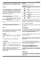
The following pictograms are shown on the tool:
Read instruction manual before use.
Wear ear protection.
Wear eye protection.
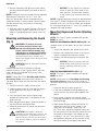
DATE CODE POSITION (FIG. 1)
The date code (s), which also includes the year of
manufacture, is printed into the housing.
Example:
2012 XX XX
Year of Manufacture
Important Safety Instructions for All
Battery Chargers
SAVE THESE INSTRUCTIONS: This manual
contains important safety and operating instruc tions
for the DCB105 battery charger.
• Beforeusingthecharger,readallinstructions
and cautionary markings on charger, battery
pack and product using the battery pack.
WARNING: Shock hazard. Do not allow
any liquid to get inside charger. Electric
shock may result.
CAUTION: Burn hazard. To reduce
the risk of injury, charge only DeWALT
rechargeable battery packs. Other types
of batteries may overheat and burst
resulting in personal injury and property
damage.
CAUTION: Children should be
supervised to ensure that they do not
play with the appliance.
NOTICE: Under certain conditions, with
the charger plugged in to the power
supply, the exposed charging contacts
inside the charger can be shorted by
foreign material. Foreign materials of
a conductive nature such as, but not
limited to, steel wool, aluminum foil or
any buildup of metallic particles should
be kept away from charger cavities.
Always unplug the charger from the
power supply when there is no battery
pack in the cavity. Unplug charger
before attempting to clean.
• DONOTattempttochargethebatterypack
with any chargers other than the ones in
this manual. The charger and battery pack are
specifically designed to work together.
• Thesechargersarenotintendedfor
any uses other than charging DeWALT
rechargeable batteries. Any other uses
may result in risk of fire, electric shock or
electrocution.
• Donotexposechargertorainorsnow.

ENGLISH
9
• Pullbyplugratherthancordwhen
disconnecting charger. This will reduce risk
of damage to electric plug and cord.
• Makesurethatcordislocatedsothatitwill
not be stepped on, tripped over or otherwise
subjected to damage or stress.
• Donotuseanextensioncordunlessit
is absolutely necessary. Use of improper
extension cord could result in risk of fire,
electric shock or electrocution.
• Whenoperatingachargeroutdoors,always
provide a dry location and use an extension
cord suitable for outdoor use. Use of a cord
suitable for outdoor use reduces the risk of
electric shock.
• Donotblocktheventilationslotsonthe
charger. The ventilation slots are located
on the top and sides of the charger. Place
the charger in a position away from any heat
source.
• Donotoperatechargerwithdamagedcord
or plug — have them replaced immediately.
• Do not operate charger if it has received
a sharp blow, been dropped or otherwise
damaged in any way. Take it to an authorised
service centre.
• Donotdisassemblethecharger;takeitto
an authorised service centre when service or
repair is required. Incorrect reassembly may
result in a risk of electric shock, electrocution or
fire.
• Incaseofdamagedpowersupplycordthe
supply cord must be replaced immediately by
the manufacturer, its service agent or similar
qualified person to prevent any hazard.
• Disconnectthechargerfromtheoutlet
before attempting any cleaning. This will
reduce the risk of electric shock. Removing
the battery pack will not reduce this risk.
• NEVERattempt to connect 2 chargers together.
• Thechargerisdesignedtooperateon
standard230Vhouseholdelectricalpower.
Do not attempt to use it on any other
voltage. This does not apply to the vehicular
charger.
SAVE THESE INSTRUCTIONS
Chargers
The DCB105 charger accepts 10.8 V, 14.4 V and
18 V Li-Ion (DCB121, DCB123, DCB140, DCB141,
DCB142, DCB180, DCB181 and DCB182) battery
packs.
This charger requires no adjustment and is designed
to be as easy as possible to operate.
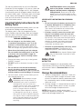
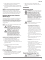
Charging Procedure (fig. 2)
1. Plug the charger into an appropriate 220 V
outlet before inserting the battery pack.
2. Insert the battery pack (j) into the charger,
making sure the pack is fully seated in the
charger. The red (charging) light will blink
continuously indicating that the charging
process has started.
3. The completion of charge will be indicated by
the red light remaining ON continuously. The
pack is fully charged and may be used at this
time or left in the charger.
NOTE: To ensure maximum performance and life of
Li-Ion batteries, charge the battery pack fully before
first use.
Charging Process
Refer to the table below for the state of charge of
the battery pack.
State of charge
charging –– –– –– ––
fully charged –––––––––––––––––
hot/coldpackdelay ––•––•––• ––•
x
problempackorcharger ••••••••••••
problempowerline ••••••••••••
This charger will not charge a faulty battery pack.
The charger will indicate faulty battery by refusing to
light or by displaying problem pack or charger blink
pattern.
NOTE: This could also mean a problem with a
charger.
If the charger indicates a problem, take the charger
and battery pack to be tested at an authorised
service centre.
Hot/Cold Pack Delay
When the charger detects a battery that is too hot
or too cold, it automatically starts a hot/cold pack
delay, suspending charging until the battery has
reached an appropriate temperature. The charger
then automatically switches to the pack charging
mode. This feature ensures maximum battery life.
XR Li-Ion tools are designed with an Electronic
Protection System that will protect the battery
against overloading, overheating or deep discharge.

ENGLISH
10
The tool will automatically turn off if the Electronic
Protection System engages. If this occurs, place the
Li-Ion battery on the charger until it is fully charged.
A cold battery pack will charge at about half the rate
of a warm battery pack. The battery pack will charge
at that slower rate throughout the entire charging
cycle and will not return to maximum charge rate
even if the battery warms.
Important Safety Instructions for All
Battery Packs
When ordering replacement battery packs, be sure
to include the catalog number and voltage.
The battery pack is not fully charged out of the
carton. Before using the battery pack and charger,
read the safety instructions below and then follow
the charging procedures outlined.
READ ALL INSTRUCTIONS
• Donotchargeorusethebatterypack
in explosive atmospheres, such as in the
presence of flammable liquids, gases or
dust. Inserting or removing the battery pack
from the charger may ignite the dust or fumes.
• Never force the battery pack into charger.
Do not modify the battery pack in any way
to fit into a non-compatible charger as
battery pack may rupture causing serious
personal injury.
• Chargethebatterypacksonlyindesignated
DeWALT chargers.
• DONOTsplash or immerse in water or other
liquids.
• Donotstoreorusethetoolandbattery
pack in locations where the temperature
may reach or exceed 40˚C (105˚F) (such as
outside sheds or metal buildings in summer).
• Forbestresults,makesurethebatterypackis
fully charged before use.
WARNING: Never attempt to open
the battery pack for any reason. If
the battery pack case is cracked or
damaged, do not insert it into the
charger. Do not crush, drop or damage
battery pack. Do not use a battery
pack or charger that has received a
sharp blow, been dropped, run over
or damaged in any way (e.g., pierced
with a nail, hit with a hammer, stepped
on). Electric shock or electrocution may
result. Damaged battery packs should
be returned to the service centre for
recycling.
CAUTION: When not in use, place
tool on its side on a stable surface
where it will not cause a tripping or
falling hazard. Some tools with large
battery packs will stand upright on the
battery pack but may be easily knocked
over.
SPECIFIC SAFETY INSTRUCTIONS FOR LITHIUM ION
(Li-Ion)
• Donotincineratethebatterypackevenifit
is severely damaged or is completely worn
out. The battery pack can explode in a fire.
Toxic fumes and materials are created when
lithium ion battery packs are burned.
• Ifbatterycontentscomeintocontactwith
the skin, immediately wash the area with
mild soap and water. If the battery liquid gets
into the eye, rinse water over the open eye for
15 minutes or until irritation ceases. If medical
attention is needed, the battery electrolyte
is composed of a mixture of liquid organic
carbonates and lithium salts.
• Contentsofopenedbatterycellsmaycause
respiratory irritation. Provide fresh air. If
symptoms persists, seek medical attention.
WARNING: Burn hazard. Battery liquid
may be flammable if exposed to spark
or flame.
Battery Pack
BATTERY TYPE
The DCG412 operates on 18 volt battery pack.
The DCB180, DCB181 or DCB182 battery packs
may be used. Refer to Technical Data for more
information.
Storage Recommendations
1. The best storage place is one that is cool and
dry away from direct sunlight and excess heat
or cold. For optimum battery performance and
life, store battery packs at room temperature
when not in use.
2. For long storage, it is recommended to store a
fully charged battery pack in a cool, dry place
out of the charger for optimal results.
NOTE: Battery packs should not be stored
completely depleted of charge. The battery pack will
need to be recharged before use.

ENGLISH
11
Labels on Charger and Battery Pack
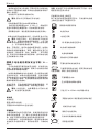
In addition to the pictographs used in this manual,
the labels on the charger and the battery pack show
the following pictographs:
Read instruction manual before use.
Charging.
Fully charged.
Hot/cold pack delay.
x
Problem pack or charger.
Problem powerline.
Do not probe with conductive objects.
Do not charge damaged battery packs.
Use only with DeWALT battery packs.
Others may burst, causing personal injury
and damage.
Do not expose to water.
Have defective cords replaced
immediately.
Charge only between 4°C and 40°C.
Discard the battery pack with due care for
the environment.
Do not incinerate the battery pack.
Charges Li-Ion battery packs.
See Technical data for charging time.
Only for indoor use.
Package Contents
The package contains:
1 Angle grinder
1 125 mm Guard (Type 27)
1 Side handle
1 Flange set
1 Two-pin spanner
1 Charger
2 Li-Ion battery packs (M2, L2 models)
1 Instruction manual
1 Exploded drawing
NOTE: Battery packs, chargers and kitboxes are not
included with N-models.
• Checkfordamagetothetool,partsor
accessories which may have occurred during
transport.
• Takethetimetothoroughlyreadand
understand this manual prior to operation.
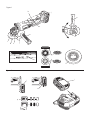
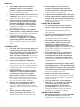
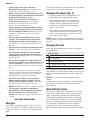
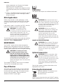
Description (fig. 1–3)
WARNING: Never modify the power
tool or any part of it. Damage or
personal injury could result.
a. Trigger switch
b. Lock-off button
c. Spindle lock button
d. Spindle
e. Side handle
f. Abrasive wheel
g. Backing flange
h. Threaded clamp nut
i. Guard
j. Battery pack
k. Guard catch
l. Lugs
m. Gear case slots
n. Adjusting screw
o. Battery release button
p. fuel gauge button
INTENDED USE
The DCG412 heavy-duty angle grinder has been
designed for professional grinding and cutting
applications.

ENGLISH
12
DO NOT use grinding wheels other than centre
depressed wheels and flap discs.
DO NOT use under wet conditions or in the
presence of flammable liquids or gases.
This heavy-duty angle grinder is a professional
power tools.
DO NOT let children come into contact with the
tool. Supervision is required when inexperienced
operators use this tool.
• Thisproductisnotintendedforusebypersons
(including children) suffering from diminished
physical, sensory or mental abilities; lack of
experience, knowledge or skills unless they are
supervised by a person responsible for their
safety. Children should never be left alone with
this product.
Electrical Safety
The electric motor has been designed for one
voltage only. Always check that the battery pack
voltage corresponds to the voltage on the rating
plate. Also make sure that the voltage of your
charger corresponds to that of your mains.
Your DeWALT charger is double insulated
in accordance with EN 60335; therefore
no earth wire is required.
If the supply cord is damaged, it must be replaced
by a specially prepared cord available through the
DeWALT service organisation.
Using an Extension Cable
An extension cord should not be used unless
absolutely necessary. Use an approved extension
cable suitable for the power input of your charger
(see Technical Data). The minimum conductor size
is 1 mm
2
; the maximum length is 30 m.
When using a cable reel, always unwind the cable
completely.
ASSEMBLY AND ADJUSTMENTS
WARNING: To reduce the risk
of serious personal injury, turn
tool off and disconnect tool from
power source before making any
adjustments or removing/installing
attachments or accessories. Before
reconnecting the tool, depress and
release the trigger switch to ensure that
the tool is off.
WARNING: Use only DeWALT battery
packs and chargers.
Inserting and Removing the
Battery Pack from the Tool (fig. 2)
NOTE: For best results, make sure your battery
pack is fully charged.
TO INSTALL THE BATTERY PACK INTO THE TOOL HANDLE
1. Align the battery pack (j) with the rails inside the
tool’s handle (fig. 2).
2. Slide it into the handle until the battery pack is
firmly seated in the tool and ensure that it does
not disengage.
TO REMOVE THE BATTERY PACK FROM THE TOOL
1. Press the battery release button (o) and firmly
pull the battery pack out of the tool handle.
2. Insert battery pack into the charger as
described in the charger section of this manual.
FUEL GAUGE BATTERY PACKS (FIG. 2)
Some DeWALT battery packs include a fuel gauge
which consists of three green LED lights that
indicate the level of charge remaining in the battery
pack.
To actuate the fuel gauge, press and hold the fuel
gauge button (p). A combination of the three green
LED lights will illuminate designating the level of
charge left. When the level of charge in the battery
is below the usable limit, the fuel gauge will not
illuminate and the battery will need to be recharged.
NOTE: The fuel gauge is only an indication of the
charge left on the battery pack. It does not indicate
tool functionality and is subject to variation based
on product components, temperature and end-user
application.
Attaching Side Handle (fig. 1)
WARNING: Before using the tool,
check that the handle is tightened
securely.
WARNING: The side handle should
always be used to maintain control of
the tool at all times.
Screw the side handle (e) tightly into one of the holes
on either side of the gear case.
To improve user comfort, the gear case will rotate
90° for cutting operations.
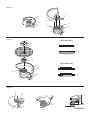
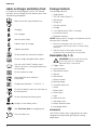
Rotating the Gear Case (fig. 1)
1. Remove the four corner screws attaching the
gear case to motor housing.

ENGLISH
13
2. Without separating the gear case from motor
housing, rotate the gear case head to desired
position.
NOTE: If the gear case and motor housing become
separated by more than 1/8" (3.17 mm), the
tool must be serviced and re-assembled by an
authorised D
eWALT service center. Failure to have
the tool serviced may cause brush, motor and
bearing failure.
3. Reinstall screws to attach the gear case to the
motor housing. Tighten screws to 20 in.-lbs.
torque. Overtightening could cause screws to
strip.
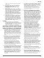
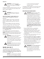
Mounting and Removing the Guard
(fig. 3)
WARNING: To reduce the risk
of serious personal injury, turn
tool off and disconnect tool from
power source before making any
adjustments or removing/installing
attachments or accessories. Before
reconnecting the tool, depress and
release the trigger switch to ensure that
the tool is off.
CAUTION: Guards must be used with
this grinder.
When using the DCG412 grinder for cutting
metal or masonry a Type 1 guard MUST be used.
Type 1 guards are available at extra cost from
DeWALT distributors.
NOTE: Please refer to the Grinding and Cutting
Accessory Chart at the end of this section to
see other accessories that can be used with these
grinders.
1. Place the tool on a table, spindle (d) up.
2. Open the guard latch (k), and align the lugs (l)
on the guard with the slots on the gear
case (m).
3. Push the guard down until the guard lugs
engage and rotate freely in the groove on the
gear case hub.
4. With the guard latch open, rotate the guard (i)
into the desired working position.
5. Close the guard latch to secure the guard on
the gear case.
CAUTION: If the guard cannot be
tightened by the adjusting screw (n), do
not use the tool. To reduce the risk of
personal injury, take the tool and guard
to a service center to repair or replace
the guard.
NOTICE: Do not tighten the adjusting
screw (n) with the clamp lever in the
open position. Undetectable damage
to the guard or the mounting hub may
result.
NOTE: Edge grinding and cutting can be performed
with Type 27 wheels designed and specified for this
purpose; 6.35 mm (1/4") thick wheels are designed
for surface grinding while 3.17 mm (1/8") wheels are
designed for edge grinding.
Mounting Depressed Center Grinding
Wheels
NOTE: The Type 27 guard supplied with grinder
MUST be used.
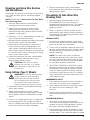
MOUNTING AND REMOVING HUBBED WHEELS (FIG. 1, 4)
Hubbed wheels install directly on the M14 threaded
spindle.
1. Thread the wheel on the spindle (d) by hand.
2. Depress the spindle lock button (c) and use a
wrench to tighten the hub of the wheel.
3. Reverse the above procedure to remove the
wheel.
NOTICE: Failure to properly seat the
wheel before turning the tool on may
result in damage to the tool or the
wheel.
MOUNTING NON-HUBBED WHEELS (FIG. 1, 4)
NOTE: The Type 27 guard supplied with grinder
MUST be used.
NOTE: Please refer to the Grinding and Cutting
Accessory Chart at the end of this section to
see other accessories that can be used with these
grinders.
1. Place the tool on a table, guard up.
2. Install the unthreaded backing flange (g) on
spindle (d) with the raised centre against the
wheel.
3. Place wheel (f) against the backing flange,
centering the wheel on the raised centre of the
backing flange.
4. While depressing the spindle lock button (c),
thread the clamp nut (h) on spindle. If the
wheel you are installing is more than 1/8"
(3.17mm) thick, place the threaded clamp nut
on the spindle so that the raised centre fits into
the center of the wheel. If the wheel you are
installing is 1/8" (3.17 mm) thick or less, place
the threaded clamp nut on the spindle so that
the raised centre is not against the wheel.

ENGLISH
14
5. While depressing the spindle lock button (c),
tighten the clamp nut with a wrench.
6. To remove the wheel, depress the spindle lock
button and loosen the threaded clamp nut with
a wrench.
NOTE: If the wheel spins after the clamp nut is
tightened, check the orientation of the threaded
clamp nut. If a thin wheel is installed with the
raised centre on the clamp nut against the wheel,
it will spin because the height of the raised centre
prevents the clamp nut from holding the wheel.
Mounting Wire Brushes and Wire
Wheels (fig. 1)
Wire cup brushes or wire wheels install directly on
the threaded spindle without the use of flanges.
Use only wire brushes or wheels provided with a
M14 threaded hub. These accessories are available
at extra cost from your local dealer or authorised
service center.
NOTE: The Type 27 guard is required when using
wire brushes and wheels.
CAUTION: To reduce the risk of
personal injury, wear work gloves
when handling wire brushes and
wheels. They can become sharp.
CAUTION: To reduce the risk
of damage to the tool, wheel
or brush must not touch guard
when mounted or while in use.
Undetectable damage could occur
to the accessory, causing wires to
fragment from accessory wheel or cup.
MOUNTING WIRE CUP BRUSHES AND WIRE WHEELS
1. Place the tool on a table, guard up.
2. Thread the wheel on the spindle by hand.
3. Depress spindle lock button (c) and use a
wrench on the hub of the wire wheel or brush to
tighten the wheel.
4. To remove the wheel, reverse the above
procedure.
NOTICE: To reduce the risk of damage
to the tool, properly seat the wheel hub
before turning the tool on.
Prior to Operation
• Installtheguardandappropriatediscorwheel.
Do not use excessively worn discs or wheels.
• Besuretheinnerandouterflangesare
mounted correctly.
• Makesurethediscorwheelrotatesinthe
direction of the arrows on the accessory and
the tool.
OPERATION
Instructions for Use
WARNING: Always observe the safety
instructions and applicable regulations.
WARNING: To reduce the risk
of serious personal injury, turn
tool off and disconnect tool from
power source before making any
adjustments or removing/installing
attachments or accessories. Before
reconnecting the tool, depress and
release the trigger switch to ensure that
the tool is off.
WARNING:
•Ensureallmaterialstobegroundor
cut are secured in place.
•Use clamps or a vice to hold
and support the workpiece to a
stable platform. It is important to
clamp and support the workpiece
securely to prevent the movement
of the workpiece and loss of control.
Movement of the workpiece or loss
of control may create a hazard and
cause personal injury.
•Applyonlyagentlepressuretothe
tool. Do not exert side pressure on the
disc.
•Alwayswearregularworkinggloves
while operating this tool.
•Thegearcasebecomesveryhot
during use.
•Alwaysinstalltheguardand
appropriate disc or wheel. Do not use
excessively worn disc or wheel.
•Besuretheinnerandouterflangeare
mounted correctly.
•Makesurethediscorwheelrotates
in the direction of the arrows on the
accessory and the tool.
•Avoidoverloading.Shouldthetool
become hot, let it run a few minutes
under no-load condition.
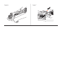
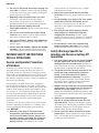
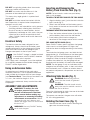
Proper Hand Position (fig. 1, 6)
WARNING: To reduce the risk of
serious personal injury, ALWAYS use
proper hand position as shown.

ENGLISH
15
WARNING: To reduce the risk of
serious personal injury, ALWAYS hold
securely in anticipation of a sudden
reaction.
Proper hand position requires one hand on the side
handle (e), with the other hand on the body of the
tool, as shown in figure 6.
Switch
WARNING: Before using the tool,
check that the handle is tightened
securely.
LOCK-OFF BUTTON AND TRIGGER SWITCH (FIG. 7)
Your cut-off tool is equipped with a lock-off
button(b).
To lock the trigger switch (a), press the lock-off
button as shown in figure 7. When the lock-off
button is depressed to the lock icon, the unit is
locked.
Always lock the trigger switch when carrying or
storing the tool to eliminate unintentional starting.
To unlock the trigger switch, press the lock-off
button (b). When the lock-off button is depressed
to the unlock icon, the unit is unlocked. The lock-off
button is colored red to indicate when the switch is
in its unlocked position.
Pull the trigger switch (a) to turn the motor ON.
Releasing the trigger switch turns the motor OFF.
NOTE: This tool has no provision to lock the switch in
the ON position, and should never be locked ON by
any other means.
WARNING: Hold the side handle and
body of the tool firmly to maintain
control of the tool at start up and during
use and until the wheel or accessory
stops rotating. Make sure the wheel has
come to a complete stop be fore laying
the tool down.
WARNING: Allow the tool to reach full
speed before touching tool to the work
surface. Lift the tool from the work
surface before turning the tool off.
Spindle Lock (fig. 1)
The spindle lock (c) is provided to prevent the
spindle from rotating when installing or removing
wheels. Operate the spindle lock only when the tool
is turned off, unplugged from the power supply, and
has come to a complete stop.
NOTICE: To reduce the risk of damage
to the tool, do not engage the spindle
lock while the tool is operating. Damage
to the tool will result and attached
accessory may spin off possibly
resulting in injury.
To engage the lock, depress the spindle lock button
(c) and rotate the spindle until you are unable to
rotate the spindle further.
EDGE GRINDING WITH GRINDING WHEELS
WARNING: Wheels used for cutting
and edge grinding may break or
kickback if they bend or twist while the
tool is being used to do cut-off work
or deep grinding. To reduce the risk
of serious injury, limit the use of these
wheels with a standard Type 27 guard
to shallow cutting and notching (less
than 13 mm [1/2"] in depth). The open
side of the guard must be positioned
away from the operator. For deeper
cutting with a Type 1 cut-off wheel, use
a closed Type 1 guard. Please refer to
the Grinding and Cutting Accessory
Chart at the end of this section to see
other accessories that can be used with
these grinders.
1. Allow the tool to reach full speed before
touching the tool to the work surface.
2. Apply minimum pressure to the work surface,
allowing the tool to operate at high speed.
Grinding rate is greatest when the tool operates
at high speed.
3. Position yourself so that the open-underside of
the wheel is facing away from you.
4. Once a cut is begun and a notch is established
in the workpiece, do not change the angle of
the cut. Changing the angle will cause the wheel
to bend and may cause wheel breakage. Edge
grinding wheels are not designed to withstand
side pressures caused by bending.
5. Remove the tool from the work surface before
turning the tool off. Allow the tool to stop
rotating before laying it down.
WARNING: Do not use edge grinding/
cutting wheels for surface grinding
applications because these wheels
are not designed for side pressures
encountered with surface grinding.
Wheel breakage and serious personal
injury may result.

ENGLISH
16
Mounting and Using Wire Brushes
and Wire Wheels
Wire wheels and brushes can be used for removing
rust, scale and paint, and for smoothing irregular
surfaces.
NOTE: Please refer to Precautions To Take When
Wire Brushing Paint.
1. Allow the tool to reach full speed before
touching the tool to the work surface.
2. Apply minimum pressure to work surface,
allowing the tool to operate at high speed.
Material removal rate is greatest when the tool
operates at high speed.
3. Maintain a 5° to 10° angle between the tool and
work surface for wire cup brushes.
4. Maintain contact between the edge of the wheel
and the work surface with wire wheels.
5. Continuously move the tool in a forward and
back motion to avoid creating gouges in the
work surface. Allowing the tool to rest on the
work surface without moving, or moving the tool
in a circular motion causes burning and swirling
marks on the work surface.
6. Remove the tool from the work surface before
turning the tool off. Allow the tool to stop
rotating before setting it down.
CAUTION: Use extra care when
working over an edge, as a sudden
sharp movement of grinder may be
experienced.
Using Cutting (Type 1) Wheels
WARNING: Do not use edge grinding/
cutting wheels for surface grinding
applications because these wheels
are not designed for side pressures
encountered with surface grinding.
Wheel breakage and injury may result.
1. Allow tool to reach full speed before touching
tool to work surface.
2. Apply minimum pressure to work surface,
allowing tool to operate at high speed. Cutting
rate is greatest when the tool operates at high
speed.
3. Once a cut is begun and a notch is established
in the workpiece, do not change the angle of
the cut. Changing the angle will cause the wheel
to bend and may cause wheel breakage.
4. Remove the tool from work surface before
turning tool off. Allow the tool to stop rotating
before setting it down.
Precautions To Take When Wire
Brushing Paint
1. Wire brushing of lead based paint is NOT
RECOMMENDED due to the difficulty of
controlling the contaminated dust. The greatest
danger of lead poisoning is to children and
pregnant women.
2. Since it is difficult to identify whether or not a
paint contains lead without a chemical analysis,
we recommend the following precautions when
wire brushing any paint:
PERSONAL SAFETY
1. No children or pregnant women should enter
the work area where the paint removal is being
done until all clean up is completed.
2. A dust mask or respirator should be worn by all
persons entering the work area. The filter should
be replaced daily or whenever the wearer has
difficulty breathing.
NOTE: Only those dust masks suitable for
working with lead paint dust and fumes should
be used. Ordinary painting masks do not offer
this protection. See your local hardware dealer
for the proper respiratory protection.
3. NO EATING, DRINKING or SMOKING should
be done in the work area to prevent ingesting
contaminated paint particles. Workers should
wash and clean up BEFORE eating, drinking
or smoking. Articles of food, drink, or smoking
should not be left in the work area where dust
would settle on them.
ENVIRONMENTAL SAFETY
1. Paint should be removed in such a manner as
to minimize the amount of dust generated.
2. Areas where paint removal is occurring should
be sealed with plastic sheeting of 4 mils
thickness.
3. Wire brushing should be done in a manner to
reduce tracking of paint dust outside the work
area.
CLEANING AND DISPOSAL
1. All surfaces in the work area should be
vacuumed and thoroughly cleaned daily for the
duration of the wire brushing project. Vacuum
filter bags should be changed frequently.
2. Plastic drop cloths should be gathered up and
disposed of along with any dust chips or other
removal debris. They should be placed in sealed

ENGLISH
17
refuse receptacles and disposed of through
regular trash pick-up procedures.
During clean up, children and pregnant women
should be kept away from the immediate work
area.
3. All toys, washable furniture and utensils used by
children should be washed thoroughly before
being used again.
Metal Applications
When using the tool in metal applications, make
sure that a residual current device (RCD) has been
inserted to avoid residual risks caused by metal
swarf.
If the power supply is shut off by the RCD, take the
tool to an authorised DeWALT repair agent.
WARNING: In extreme working
conditions, conductive dust can
accumulate inside the machine housing
when working with metal. This can
result in the protective insulation in the
machine becoming degraded with a
potential risk of an electrical shock.
To avoid build-up of metal swarf inside the machine,
we recommend to clear the ventilation slots on a
daily basis. Refer to Maintenance.
MAINTENANCE
Your DeWALT power tool has been designed to
operate over a long period of time with a minimum
of maintenance. Continuous satisfactory operation
depends upon proper tool care and regular cleaning.
WARNING: To reduce the risk
of serious personal injury, turn
tool off and disconnect tool from
power source before making any
adjustments or removing/installing
attachments or accessories. Before
reconnecting the tool, depress and
release the trigger switch to ensure that
the tool is off.
The charger and battery pack are not serviceable.
There are no serviceable parts inside.
Pop-off Brushes
The motor will be automatically shut off indicating
that the carbon brushes are nearly worn out and
that the tool needs servicing. The carbon brushes
are not user-serviceable. Take the tool to an
authorised DeWALT repair agent.
Lubrication
Your power tool requires no additional lubrication.
Cleaning
WARNING: Blow dirt and dust out of
the main housing with dry air as often as
dirt is seen collecting in and around the
air vents. Wear approved eye protection
and approved dust mask when
performing this procedure.
WARNING: Never use solvents or
other harsh chemicals for cleaning the
non-metallic parts of the tool. These
chemicals may weaken the materials
used in these parts. Use a cloth
dampened only with water and mild
soap. Never let any liquid get inside the
tool; never immerse any part of the tool
into a liquid.
CHARGER CLEANING INSTRUCTIONS
WARNING: Shock hazard. Disconnect
the charger from the AC outlet before
cleaning. Dirt and grease may be
removed from the exterior of the charger
using a cloth or soft non-metallic brush.
Do not use water or any cleaning
solutions.
Optional Accessories
WARNING: Since accessories, other
than those offered by DeWALT, have
not been tested with this product, use
of such accessories with this tool could
be hazardous. To reduce the risk of
injury, only DeWALT recommended
accessories should be used with this
product.
Consult your dealer for further information on the
appropriate accessories.
Protecting the Environment
Separate collection. This product must
not be disposed of with normal
household waste.
Should you find one day that your DeWALT product
needs replacement, or if it is of no further use to you,

ENGLISH
18
do not dispose of it with household waste. Make this
product available for separate collection.
Separate collection of used products and
packaging allows materials to be
recycled and used again. Re-use of
recycled materials helps prevent
environmental pollution and reduces
the demand for raw materials.
Local regulations may provide for separate collection
of electrical products from the household, at
municipal waste sites or by the retailer when you
purchase a new product.
DeWALT provides a facility for the collection and
recycling of DeWALT products once they have
reached the end of their working life. To take
advantage of this service please return your product
to any authorised repair agent who will collect them
on our behalf.
You can check the location of your nearest
authorised repair agent by contacting your local
DeWALT office at the address indicated in this
manual. Alternatively, a list of authorised DeWALT
repair agents and full details of our after-sales
service and contacts are available on the Internet at:
www.2helpU.com.
Rechargeable Battery Pack
This long life battery pack must be recharged when
it fails to produce sufficient power on jobs which
were easily done before. At the end of its technical
life, discard it with due care for our environment:
• Runthebatterypackdowncompletely,then
remove it from the tool.
• Li-Ioncellsarerecyclable.Takethemtoyour
dealer or a local recycling station. The collected
battery packs will be recycled or disposed of
properly.
ページが読み込まれています...
ページが読み込まれています...
ページが読み込まれています...
ページが読み込まれています...
ページが読み込まれています...
ページが読み込まれています...
ページが読み込まれています...
ページが読み込まれています...
ページが読み込まれています...
ページが読み込まれています...
-
 1
1
-
 2
2
-
 3
3
-
 4
4
-
 5
5
-
 6
6
-
 7
7
-
 8
8
-
 9
9
-
 10
10
-
 11
11
-
 12
12
-
 13
13
-
 14
14
-
 15
15
-
 16
16
-
 17
17
-
 18
18
-
 19
19
-
 20
20
-
 21
21
-
 22
22
-
 23
23
-
 24
24
-
 25
25
-
 26
26
-
 27
27
-
 28
28
-
 29
29
-
 30
30


他の言語で
- English: DeWalt DCG412 User manual
関連論文
その他のドキュメント
-
Makita M0920 ユーザーマニュアル
-
Makita GA7020 ユーザーマニュアル
-
Makita GA035G Cordless Angle Grinder ユーザーマニュアル
-
Stanley STCT1840 ユーザーマニュアル
-
Hitachi G 23SW Handling Instructions Manual
-
BLACK+DECKER G720R ユーザーマニュアル
-
-
Hilti SSH 6-A22 取扱説明書
-
-
BLACK+DECKER BPGS8100 ユーザーマニュアル