
Operating Instructions
操作说明书
Pressure Balance
GB
压力天平
CN
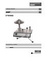
CPB5800
Pressure Balance CPB5800
CPB5800 压力天平

Pressure Balance
CPB5800
GB
WIKA Operating Instructions Pressure Balance Version 1.1
2
GB
Operating Instructions Pressure Balance
Page 4 - 37
CN
压力天平操作说明书
第 38 - 72 页
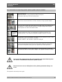
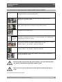
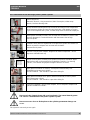
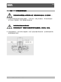
Information
This symbol provides you with information, notes and tips.
Warning!
This symbol warns you against actions that can cause injury to people or
damage to the instrument.

Pressure Balance
CPB5800
GB
WIKA Operating Instructions Pressure Balance Version 1.1
3
C
C
o
o
n
n
t
t
e
e
n
n
t
t
s
s
1. General .................................................................................................................................................... 5
1.1 General Instructions ............................................................................................................................... 5
1.2 Safety Instructions.................................................................................................................................. 6
2. Product Description ............................................................................................................................... 7
2.1 General Product Information ................................................................................................................. 7
2.2 Basic principle of the Pressure Balance ................................................................................................ 8
2.3 Environmental factors ............................................................................................................................ 9
2.3.1 Local fluctuations in gravity-value ...................................................................................................... 9
2.3.2 Temperature (Piston/Cylinder) ......................................................................................................... 10
2.3.3 Ambient conditions ........................................................................................................................... 10
2.3.4 How the cross-sectional area responds to pressure ........................................................................ 11
2.4 Arrangement of control elements ........................................................................................................ 11
2.4.1 Standard hydraulic base................................................................................................................... 12
2.4.2 High-pressure hydraulic base .......................................................................................................... 13
3. Commissioning and Operation ....................................................................................................... 14
3.1 Preparation .......................................................................................................................................... 14
3.1.1 Setting up the Device ....................................................................................................................... 14
3.1.2 Hydraulic pressure media used ........................................................................................................ 14
3.1.3 Installing the piston-cylinder system ................................................................................................ 15
3.1.3.1 Connection for piston-cylinder system with G3/4 B (male) thread ................................................ 16
3.1.3.2 Connection for piston-cylinder system with ConTect quick connector ......................................... 17
3.1.3 Connecting the device under test ..................................................................................................... 18
3.1.4 Venting the System .......................................................................................................................... 18
3.2 Operation ............................................................................................................................................. 19
3.2.1 Procedure for single-range piston-cylinder system 1,600 psi or 120 bar ......................................... 19
3.2.1.1 Mass loading ................................................................................................................................. 19
3.2.1.2 Approaching the pressure value ................................................................................................... 19
3.2.1.3 Pressure stable ............................................................................................................................. 19
3.2.2 Procedure for single-range piston-cylinder system 4,000 psi or 300 bar ......................................... 20
3.2.2.1 Mass load ...................................................................................................................................... 20
3.2.2.2 Approaching the pressure value ................................................................................................... 20
3.2.2.3 Pressure stable ............................................................................................................................. 20
3.2.3 Procedure for all dual-range piston-cylinder systems ...................................................................... 21
3.2.3.1 Mass load ...................................................................................................................................... 21
3.2.3.2 Approaching the pressure value ................................................................................................... 21
3.2.3.3 Pressure stable ............................................................................................................................. 21
3.2.4 Next pressure level ........................................................................................................................... 22
3.2.5 Releasing pressure .......................................................................................................................... 22
3.3 Disassembly ......................................................................................................................................... 23
4. Troubleshooting measures ................................................................................................................ 24
5. Maintenance and Care ........................................................................................................................ 25
5.1 Cleaning ............................................................................................................................................... 25
5.1.1 Piston-cylinder system ..................................................................................................................... 25
5.1.1.1 Procedure for single-range piston-cylinder system 1,600 psi or 120 bar ..................................... 26
5.1.1.2 Procedure for single-range piston-cylinder system 4,000 psi or 300 bar ..................................... 27
5.1.1.3 Procedure for all dual-range piston-cylinder systems ................................................................... 28
5.1.2 Mass set ............................................................................................................................................ 29

Pressure Balance
CPB5800
GB
WIKA Operating Instructions Pressure Balance Version 1.1
4
5.2 Consumable Parts ............................................................................................................................... 29
5.3 Changing the hydraulic pressure medium ........................................................................................... 29
5.3.1 Removing hydraulic pressure medium ............................................................................................. 29
5.3.2 Filling in of hydraulic pressure medium ............................................................................................ 29
5.3.3 Venting of the System (after Complete Filling only) ......................................................................... 30
5.4 Recalibration ........................................................................................................................................ 30
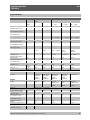
6. Specifications ...................................................................................................................................... 31
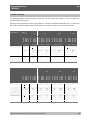
7. Tables of masses ................................................................................................................................ 34
8. Accessories ......................................................................................................................................... 36

Pressure Balance
CPB5800
GB
WIKA Operating Instructions Pressure Balance Version 1.1
5
1. General
1.1 General Instructions
In the following chapters detailed information on the CPB5800 pressure balance and its proper use can
be found.
Should you require further information, or should there be problems which are not dealt within detail in
the operating instructions, please contact the address below:
DH-Budenberg
A Division of WIKA Instruments Ltd.
10 Huntsman Drive, Northbank Ind. Est.
Irlam, Manchester • M44 5EG United Kingdom
Tel.: (+44) 844 406 0086
Fax: (+44) 844 406 0087
E-Mail: sales@dh-budenberg.co.uk
WIKA Alexander Wiegand SE & Co. KG
Alexander Wiegand Strasse
D-63911 Klingenberg
Tel.: (+49) 9372/132-0
Fax: (+49) 9372/132-406
E-Mail: info@wika.com
If nothing to the contrary is agreed, the pressure balance is calibrated in compliance with the currently
valid body of international regulations and can be referred directly to a national standard.
The warranty period for the pressure balance is 24 months according to the general terms of supply of
ZVEI.
The guarantee is void if the appliance is put to improper use or if the operating instructions are not
observed or if an attempt is made to open the appliance or to release attachment parts or the tubing.
We also point out that the content of these operating instructions neither forms part of an earlier or
existing agreement, assurance or legal relationship nor is meant to change these. All obligations of
WIKA Alexander Wiegand SE & Co. KG result from the respective sales contract and the general
business terms of WIKA Alexander Wiegand SE & Co. KG.
WIKA is a registered trade mark of WIKA Alexander Wiegand SE & Co. KG.
Names of companies or products mentioned in this handbook are registered trade marks of the
manufacturer.
The devices described in this manual represent the latest state of the art in terms of their design,
dimension and materials. We reserve the right to make changes to or replace materials without any
obligation to give immediate notification.
Duplication of this manual in whole or in part is prohibited.
© 2012 Copyright WIKA Alexander Wiegand SE & Co. KG. All rights reserved.

Pressure Balance
CPB5800
GB
WIKA Operating Instructions Pressure Balance Version 1.1
6
1.2 Safety Instructions
Read these operating instructions carefully prior to operating the pressure
balance CPB5800. Its trouble-free operation and reliability cannot be guaranteed
unless the safety advice given in this manual is followed when using the device.
1. The system must only be operated by trained and authorised personnel who understand the manual
and can work according to it.
2. Trouble-free operation and reliability of the device can only be guaranteed so long as the conditions
stated under "Setting up the device" are taken into consideration.
3. The CPB5800 always has to be handled with the care required for any precision instrument (protect
from humidity, impacts and extreme temperatures). The device, the piston-cylinder-system and the
mass-set must be handled with care (don't throw, hit, etc.) and protected from contamination. By no
means apply any force to the operating elements of the CPB5800.
4. If the device is moved from a cold to a warm environment, you should therefore ensure the device
temperature has adjusted to the ambient temperature before operational use.
5. If the equipment is damaged and operates no longer safely, then it should be taken out of service
and securely marked in such a way so that it is not used until repaired.
Operator safety may be at risk if:
■ There is visible damage to the device
■ The device is not working as specified
■ The device has been stored under unsuitable conditions for an extended period of time.
If there is any doubt, please return the device to the manufacturer for repair or servicing.
6. Customers must not attempt to alter or repair the device themselves. If the instrument is opened or
attachment parts or the tubing are released, its trouble-free operation and reliability is impaired and
may endanger the operator. Please return the device to the manufacturer for any repair or
maintenance work.
7. Only original type or OEM specified seals should be used in this instrument.
8. Any procedure not included in the following instructions or outside of the manual must not be
attempted.

Pressure Balance
CPB5800
GB
WIKA Operating Instructions Pressure Balance Version 1.1
7
2 Product Description
2.1 General Product Information
■ Application
Pressure balances are the most accurate instruments for the calibration of electronic or mechanical
pressure measuring instruments. The direct measurement of pressure, according to its definition as a
quotient of force and area, and the use of high-quality materials result in small uncertainties of
measurement and an excellent long-term stability.
For these reasons pressure balances have already been used in calibration laboratories of industry,
national institutes and research labs for many years. Due to the integrated pressure generation and the
purely mechanical measuring principle the CPB5800 is also ideally suited for on-site use as well as
service and maintenance purposes.
■ Piston-cylinder measuring system
Pressure is defined as a quotient of force and area. Correspondingly, the core of the CPB5800 is a very
precisely manufactured piston/cylinder system. The piston and cylinder are manufactured from
hardened steel and tungsten carbide, respectively, and are very well protected in a solid stainless
steel/hardened tool steel housing against impacts or contamination from outside.
As a standard the connection of the piston-cylinder system is a G3/4 female thread. The patented
ConTect quick connector is available as an option. This enables the piston-cylinder system to be
changed quickly and safely without any tools.
The CPS5800 piston-cylinder systems are available in two fundamentally different designs, depending
on measuring range.
■ Single-range piston-cylinder systems (for measuring ranges 120 bar and 300 bar or 1,600 psi and
4,000 psi respectively)
■ Dual-range piston-cylinder systems (for measuring ranges 700 bar, 1,200 bar and 1,400 bar or
10,000 psi, 16,000 psi and 20,000 psi respectively)
The accuracy is 0.015 % as a standard (optional also to 0.006 %) of reading.
The dual-range piston-cylinder system offers two measuring ranges in one housing with automatic
measuring range switching from low-pressure to high-pressure pistons. This provides the user with an
extremely flexible measuring instrument that can cover a wide measuring range with high accuracy,
with only one piston-cylinder unit and one set of masses. Additionally two test points can automatically
be achieved by the operator loading the masses only once (low pressure – high pressure area
utilisation).
The entire construction design of the piston-cylinder unit and the very precise manufacturing of the
piston and the cylinder stand for excellent operating characteristics with a long free rotation time and
low fall rates and for a very high long term stability. Therefore the recommended re-calibration interval
is 2 up to 5 years depending on the conditions of usage.

Pressure Balance
CPB5800
GB
WIKA Operating Instructions Pressure Balance Version 1.1
8
■ Functioning
Depending on the measuring range of the device under test the operator can fit the instrument base
with the corresponding system. In order to generate the individual test points, the piston-cylinder
system is loaded with masses. The weight applied is proportional to the desired pressure and provided
by using optimally graduated weights. These weights are manufactured to standard gravity (9.80665
m/s²) although they can be adjusted for customers specific location/gravity value.
The integrated priming pump and the 250 ml tank enable large test volumes to be easily filled and
pressurised. For further pressure increases and fine adjustment, a very precisely-controllable spindle
pump is fitted, which is self-contained with in the pump body when in use.
As soon as the measuring system reaches equilibrium, there is a balance of forces between the
pressure and mass load applied.
The excellent quality of the system ensures that this pressure remains stable over several minutes, so
that the pressure value for comparative measurements can be read without any problems, or also so
that more complex adjustments can be carried out on the device under test.
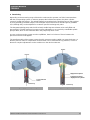
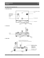
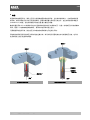
CPS5800 single-range piston-cylinder system
CPS5800 dual-range piston-cylinder system
Pressure p
High-pressure piston
Low-pressure piston
=High-pressure cylinder
Force F
Force F
Cross-sectional
area A
Pressure p

Pressure Balance
CPB5800
GB
WIKA Operating Instructions Pressure Balance Version 1.1
9
2.2 Basic principle of the Pressure Balance
Their operating principle is based on the physical definition of pressure, the quotient of force and area.
Force
Pr essure
Area
The key element of the pressure balance is a precision-manufactured piston-cylinder system with a
precisely measured cross-sectional area.
To apply a pressure charge to the system, the piston is placed under a load with (calibrated) masses.
Each mass from the set of masses is identified by a nominal weight, which generates a pressure value
in the system (assuming standard reference conditions). Each mass has a number and in the
calibration certificate describing the mass value to each mass with its resultant pressure value. The
masses are chosen according to the desired pressure value.
After that, the integrated spindle pump increases the pressure until the masses are in a floating state.
2.3 Environmental factors
The piston pressure gauge is calibrated to standard reference conditions when it leaves the factory
(depending on customer specifications).
If there are significant deviations between the application conditions and the defined reference
conditions, appropriate corrections must be made.
Following are the main factors that enter into play and must be considered.
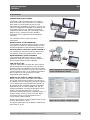
These corrections can be made automatically with the Calibrator Unit CPU6000
(see accessories point 8)!
2.3.1 Local fluctuations in gravity-value
The local force of gravity is subject to major fluctuations caused by geographical variation.
The value may differ from one place on earth to another by as much as 0.5 %. Since this value has a
direct effect on the measurement, it is essential that it be taken into consideration.
The masses can even be adjusted during manufacturing to match the location where they will be used.
Another option, especially if the device will be used at multiple locations, is to perform a calibration to
the standard gravity,
"Standard-g = 9.80665 m/s
2
".
Then a correction must be performed for each measurement according to the formula below:
g Application site
True pressure Nominal value
S tandard g
Example:
Local gravity set during manufacturing: 9.806650 m/s
2
Locale gravity at application site: 9.811053 m/s
2
Nominal pressure: 100 bar
g
Local
9.81105
True pressure: p p
Nominal
100bar 100.0449bar
g
Standard
9.80665
Without the correction, measurements would differ from the nominal applied pressure by 0.05%.

Pressure Balance
CPB5800
GB
WIKA Operating Instructions Pressure Balance Version 1.1
10
2.3.2 Temperature (Piston-cylinder)
The effective area of the piston-cylinder system is influenced by temperature.
The effect depends on the material used and is described by the temperature coefficient (TK).
In the event of deviations from standard reference conditions (typically 20°C), the following formula
must be used to make a correction:
1
True pressure Nominal value
1tAppl tReferenceTK
Example:
Reference temperature: 20°C
Temperature during use: 23°C
TK: 0.0022%
1
True pressure
100bar 99.99340bar
123 202.2
5
Without the correction, measurements would differ from the nominal applied pressure by 0.007%.
2.3.3 Ambient conditions
The effects of ambient conditions
■ air pressure
■ room temperature
■ relative humidity
should always be taken into consideration if the highest level of accuracy is required.
Fluctuations in ambient conditions change air density.
The air density affects the pressure through the buoyancy of the masses:
Air density
Weight
Nominal weight 1
Weight density
The air density is typically 1.2 kg/m3
The density of the masses (non-magnetic steel) is 7900 kg/m3
A fluctuation of 5% in the relative humidity causes an additional uncertainty in the measurement of
about 0.001%.

Pressure Balance
CPB5800
GB
WIKA Operating Instructions Pressure Balance Version 1.1
11
2.3.4 How the effective area responds to pressure
At higher pressures, the effective cross-sectional surface changes due to the pressure load.
The ratio of the cross-section and prevailing pressure is linear within an initial approximation. It is
represented by the coefficient of expansion caused by pressure distortion ().
Nominal pressure
True pressure
1
Nominal pressure
Example:
Measuring point: 1000 bar
System with distortion coefficient: 10
-7
1/bar:
1000
True pressure bar
999.90bar
1110
-7
1000
Without the correction, measurements would differ from the nominal applied pressure by 0.01%.
2.4 Arrangement of control elements
The CPB5800 instrument bases are available in 2 variants:
■ Standard hydraulic base
-
up to max 1,200 bar / 16,000 psi
-
with integrated pressure generation through priming pump and spindle pump
-
tubing made of stainless steel (1.4404), 6 x 2 mm
-
Standard pressure transmission medium: mineral oil
Optional: Sebacate oil, brake fluid, Skydrol or Fomblin oil
■ High-pressure hydraulic base
-
up to max 1,400 bar / 20,000 psi
-
with integrated pressure generation through priming pump and spindle pump
-
tubing made of stainless steel (1.4404), 6 x 2 mm
-
Pressure transmission medium: mineral oil or Sebacate oil
As a standard both instruments bases are fitted with a connection for the piston-cylinder system with
G3/4 B (male) thread.
The patented ConTect quick connector can be installed as an option allowing a quick and safe change
of the piston-cylinder system without the need for tools (not available for the hydraulic high-pressure
version!).
The connection of the test item is made without tools using a quick-connection. Via the freely-rotating
knurled nut, the test item can be oriented as required. As standard, a threaded insert with a G1/2
female thread is provided. Other threaded inserts are available to connect the most common pressure
measuring instruments.

Pressure Balance
CPB5800
GB
WIKA Operating Instructions Pressure Balance Version 1.1
12
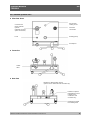
2.4.1 Standard hydraulic base
■ View from above
■ Front view
■ Rear view
Rotating foot studs
for levelling base
Interface to piston
temperature sensor
(optional and in
combination with
CPU6000 only)
Interface to float position sensor
(optional and in combination with CPU6000 only)
Outlet
valve
Priming pump
Test item
connection
Oil reservoir
sealing screw
Connector for
piston-cylinder
system
(optional ConTect
quick connection)
Level
Screwpress

Pressure Balance
CPB5800
GB
WIKA Operating Instructions Pressure Balance Version 1.1
13
2.4.2 High-pressure hydraulic base
■ View from above
■ Front view
■ Rear view
Interface to piston
temperature sensor
(optional and in
combination with
CPU6000 only)
Rotating foot studs
for levelling base
Interface to float position sensor
(optional and in combination with CPU6000 only)
Outlet
valve
Screwpress
Priming pump
Oil reservoir sealing
screw
Connector for
piston-cylinder
system G3/4
B (male)
thread
Level

Pressure Balance
CPB5800
GB
WIKA Operating Instructions Pressure Balance Version 1.1
14
3. Commissioning and Operation
3.1 Preparation
3.1.1 Setting up the Device
■ Set up the pressure balance on a solid surface. If it is not resting on a solid foundation or is subject
to vibrations, measurements and safety could be affected. This should be avoided.
■ If no temperature control system is present, the device should at least not be placed near a heat
element or window. This will reduce drafts and warm air flows as much as possible.
■ The spirit level should be used to level the assembly. At this time, rough levelling can be performed
without the piston-cylinder system. Using the rotating foot studs, position the device so that it is
horizontal. For uppermost accuracy, the spirit level should be put on top of the fitted piston and its
level adjusted to the horizontal.
■ Place the star handle with knobs onto the spindle pump. Ensure that the spring-loaded thrust pad
engages into the star handle bushing.
■ We recommend unscrewing the spindle pump completely when you start to record measurement
values, (turning anticlockwise) to allow enough swept displacement for measurements. The outlet
valve must be opened during this process.
■ The oil container may need to be filled, or refilled (volume 250 ml). For this purpose, the locking
screw with the oil filling symbol on top of the basement must be opened. Special oil must be used for
refilling (1 litre supplied, or available as accessory). The system must be vented before initial filling,
or after a complete oil change. For this purpose, please proceed according to section 5.3.3.
■ The protection film on the screwed drain plug of the oil container need to be removed before
operating (coverage of the ventilation hole during transportation).
3.1.2 Hydraulic pressure media used
Mineral oil based hydraulic fluid
An hydraulic mineral oil with a viscosity grade VG22 is used as standard.
Certain customers may wish to use the piston unit on other hydraulic fluids. Before
attempting this, the following should be checked:
Pressure medium is compatible with bronze, hardened tool steel, tungsten carbide and
with o-rings/composite seals used in the assembly. Special seal kits are available for
certain pressure media.
The new pressure medium being used will have inherent physical properties (density,
surface tension) that may affect the uppermost accuracy of the unit. Units that have
been manufactured for a non-standard pressure medium will have had its calibrated
mass adjusted for the fluids buoyancy and surface tension components. If the piston
unit has not been specially calibrated, the accuracy of the unit will be reduced, and this
should be taken into account.

Pressure Balance
CPB5800
GB
WIKA Operating Instructions Pressure Balance Version 1.1
15
Skydrol 500B
The instrument base is also available for use on Skydrol 500B or any other phosphate ester based fire
resistant liquid. This base is fitted with Ethylene Polypropylene (EP) seals. The operating characteristics
of the piston-cylinder system should be tested on Skydrol. EP seals are not suitable for mineral oils.
Note that continual immersion of the instrument housing in Skydrol will cause
deterioration. Spillage should be wiped off the housing / cover immediately.
Brake fluids
The instrument base for use on non-petroleum based brake fluids should be ordered fitted with EP
seals and the operating characteristics of the piston-cylinder system should be tested on the liquid. This
liquid is known by the following names:
FMVSS No.116, DOT3 or DOT4, SAE J 1 703, BS AU 174:Part 2, IS04925.
Other fluids
The instrument base can be used on silicone based fluids, sebacate based fluids, or inert
perfluorinatedpolyethers such as Fluorolube, Fomblin, Halocarbon, which are of the viscosity as the
standard mineral oil based hydraulic fluid mentioned above and are chemically inert, being suitable for
contact with metals and with the nitrile seals which are standard on the base.
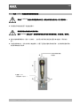
3.1.3 Installing the piston-cylinder system
■ The piston-cylinder system that is used depends on the device to be tested. You should select a
system with a comparable or higher measuring range.
■ The connection for the piston-cylinder system in the instrument base is available in 2 different
versions:
-
Connection for piston-cylinder system with G3/4 B (male) thread (see section 3.1.3.1)
-
Connection for piston-cylinder system with ConTect quick connector, not for the 1,400 bar-version
(see section 3.1.3.2)

Pressure Balance
CPB5800
GB
WIKA Operating Instructions Pressure Balance Version 1.1
16
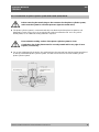
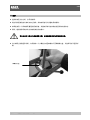
3.1.3.1 Connection for piston-cylinder system with G3/4 B (male) thread
Before removing the transit plug on the connector for the piston-cylinder system,
make sure the system is not under pressure (open the outlet valve).
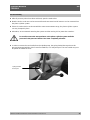
■ The piston-cylinder system is connected vertically onto the thread of the piston receptacle, and
tightened by hand. Excess force is not required to achieve an effective seal. An O-ring seal is
already fitted, so no additional sealing material is required.
Ensure that the sealing surface of the piston-cylinder system is clean.
Check the o-ring in the piston stand is correctly seated and for any sign of wear.
Replace, if necessary.
■ For an exact alignment of the device, the spirit level may be removed from the base plate and placed
on the top of the fitted piston-cylinder system. This will ensure the most accurate levelling of the
piston-cylinder system.
Oil collecting tray
Temperature sensor,
optional

Pressure Balance
CPB5800
GB
WIKA Operating Instructions Pressure Balance Version 1.1
17
3.1.3.2 Connection for piston-cylinder system with ConTect quick connector
Before releasing the transit plug in the ConTect quick-release mechanism, make
sure the system is not under pressure (open the outlet valve).
■ Place the piston-cylinder system vertically in the quick connector.
Ensure that the sealing surface of the piston-cylinder system is clean.
Check the o-ring in the ConTect stand is correctly seated and for any sign of
Replace, if necessary.
■ Turning the butterfly screw about one and a half turn clockwise (as far as it will go) is enough to
screw the system in place with an automatic seal (finger-tight).
■ For an exact alignment of the device, the spirit level may be removed from the base plate and placed
on the top of the fitted piston-cylinder system. This will ensure the most accurate levelling of the
piston-cylinder system.
1.
4.
2.
3.
Put spirit level on
top of piston
O-ring 4 x 2.2
(see accessories section 8.)

Pressure Balance
CPB5800
GB
WIKA Operating Instructions Pressure Balance Version 1.1
18
3.1.3 Connecting the device under test
■ Place the device to be calibrated/verified in the quick connector with the knurled nut. It can be freely
positioned. Hand-tightening will suffice for effective sealing.
■ To calibrate instruments with rear/back entry connections, use the 90° angle connection (see
accessories section 8).
Check the o-ring in the test stand is correctly seated and for any sign of wear.
Replace, if necessary.
Please see to it, that each instrument mounted to the pressure balance must be
clean inside.
■ The quick connector comes equipped with a G 1/2 threaded insert in the standard delivery package.
When you are calibrating devices with different connection threads, the threaded inserts
can be changed as appropriate (see accessories "Adapter Set"). For short connection
threads an additional sealing insert (order no. 2011514 resp. content of the adapter set)
can be mounted onto the existing sealing surface in the knurled nut.
3.1.4 Venting the system
After installing the piston-cylinder system and the device under test, air may be trapped in the system.
The system may be vented before beginning the calibration using the following procedure:
■ The piston-cylinder system and the device under test must be clamped, and the complete mass set
must be loaded on the piston-cylinder system.
■ Generate a pressure of approximately 50 bar using the priming pump
■ Increase the pressure with the spindle pump until just below the final value of the measuring range
of the piston-cylinder system, or of the device under test (the smaller pressure range is the decisive
factor).
Important: The piston-cylinder system must remain in its lower position for this
operation, i.e. not yet moving into equilibrium.
■ Open the outlet valve slowly, any trapped air will escape into the tank
This procedure may need to be repeated 1 to 2 times in order to remove all trapped air.
The device is now ready to use.
Threaded insert
Knurled nut
O-ring 8 x 2
(see accessories section 8.)

Pressure Balance
CPB5800
GB
WIKA Operating Instructions Pressure Balance Version 1.1
19
3.2 Operation
3.2.1 Procedure for single-range piston-cylinder system 1,600 psi or 120 bar
3.2.1.1 Mass loading
■ Load the piston head with masses equivalent to the required pressure calibration point required.
Ensure the masses are correctly located in its respective spigot/recess.
Each mass has the following markings:
-Pressure Value
-Piston Area
-Mass set number
For high accuracy calibration, an additional marking (letter or letter/number combination)
is marked on the mass. This is to identify masses of similar nominal pressure values, and
thus obtain the actual mass value (grams) of said item.
■ This piston-cylinder unit has a basic head mass equivalent to 10 psi. If calibration is required in
another pressure unit, the first mass applied to the piston head should be the make-up mass (small
mass with ‘+PISTON’ marking).
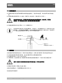
3.2.1.2 Approaching the pressure value
■ The system must first be filled with oil and pre-compressed.
■ For this the outlet valve must be closed.
■ Operate the priming pump for several strokes. The pressure increases to a maximum of about 50
bar (depending on the volume of the connected test specimen).
■ After that, increase the pressure by turning the built-in spindle pump clockwise.
■ Just before the generated pressure reaches the actual calibration point, the masses should be
rotated by hand (approx 30-40 RPM) to ensure that the piston is in free-rotation. Care should be
applied when rotating the masses that no un-necessary transverse loads are applied to the piston.
Never rotate the piston-cylinder unit, if the piston is in the lower or upper block
position.
3.2.1.3 Pressure stable
■ Continue generating pressure until the system is in a state of equilibrium.
■ As the pressure calibration point is achieved, the piston will begin to move in an upward direction to
its ‘FLOATING’ position. The ‘FLOATING’ (free rotation) position is between 1-7mm above the
cylinder. To confirm this, the operator can press down lightly (use index finger) onto the top of the
masses applied. If the piston and masses appear to bounce (move freely up and down) the piston
unit is at pressure value of masses applied.
As there is only a small pressure change required between the piston floating/not
floating we recommend turning the pump spindle slowly and evenly clockwise.
■ The piston and thus the test pressure as well now remain stable for several minutes.

Pressure Balance
CPB5800
GB
WIKA Operating Instructions Pressure Balance Version 1.1
20
3.2.2 Procedure for single-range piston-cylinder system 4,000 psi or 300 bar
3.2.2.1 Mass load
■ The piston head has a tapped hole in its uppermost surface. To achieve its initial start pressure
value (30 psi or 2 bar) a designated hexagonal mass must be screwed into the piston head. This
should be applied before starting any calibration.
■ Load the piston head with masses equivalent to the required pressure calibration point required.
Ensure the masses are correctly located in its respective spigot/recess.
Each mass has the following markings:
-Pressure Value
-Piston Area
-Mass set number
For high accuracy calibration, an additional marking (letter or letter/number combination)
is marked on the mass. This is to identify masses of similar nominal pressure values, and
thus obtain the actual mass value (grams) of said item.
3.2.2.2 Approaching the pressure value
■ The system must first be filled with oil and pre-compressed.
■ For this the outlet valve must be closed.
■ Operate the priming pump for several strokes. The pressure increases to a maximum of about 50
bar (depending on the volume of the connected test specimen).
■ After that, increase the pressure by turning the built-in spindle pump clockwise.
■ Just before the generated pressure reaches the actual calibration point, the masses should be
rotated by hand (approx 30-40 RPM) to ensure that the piston is in free-rotation. Care should be
applied when rotating the masses that no un-necessary transverse loads are applied to the piston.
Never rotate the piston-cylinder unit, if the piston is in the lower or upper block
position.
3.2.2.3 Pressure stable
■ Continue generating pressure until the system is in a state of equilibrium.
■ As the pressure calibration point is achieved, the piston will begin to move in an upward direction to
its ‘FLOATING’ position. The ‘FLOATING’ (free rotation) area is when the bottom edge of the
auxiliary cylinder fitted to the piston head has risen to a position within the knurled area of the stud
fitted to the piston unit. To confirm this, the operator can press down lightly (use index finger) onto
the top of the masses applied. If the piston and masses appear to bounce (move freely up and down)
the piston unit is at pressure value of masses applied.
As there is only a small pressure change required between the piston floating/not
floating we recommend turning the pump spindle slowly and evenly clockwise.
■ The piston and thus the test pressure as well now remain stable for several minutes.
ページが読み込まれています...
ページが読み込まれています...
ページが読み込まれています...
ページが読み込まれています...
ページが読み込まれています...
ページが読み込まれています...
ページが読み込まれています...
ページが読み込まれています...
ページが読み込まれています...
ページが読み込まれています...
ページが読み込まれています...
ページが読み込まれています...
ページが読み込まれています...
ページが読み込まれています...
ページが読み込まれています...
ページが読み込まれています...
ページが読み込まれています...
ページが読み込まれています...
ページが読み込まれています...
ページが読み込まれています...
ページが読み込まれています...
ページが読み込まれています...
ページが読み込まれています...
ページが読み込まれています...
ページが読み込まれています...
ページが読み込まれています...
ページが読み込まれています...
ページが読み込まれています...
ページが読み込まれています...
ページが読み込まれています...
ページが読み込まれています...
ページが読み込まれています...
ページが読み込まれています...
ページが読み込まれています...
ページが読み込まれています...
ページが読み込まれています...
ページが読み込まれています...
ページが読み込まれています...
ページが読み込まれています...
ページが読み込まれています...
ページが読み込まれています...
ページが読み込まれています...
ページが読み込まれています...
ページが読み込まれています...
ページが読み込まれています...
ページが読み込まれています...
ページが読み込まれています...
ページが読み込まれています...
ページが読み込まれています...
ページが読み込まれています...
ページが読み込まれています...
ページが読み込まれています...
ページが読み込まれています...
ページが読み込まれています...
ページが読み込まれています...
ページが読み込まれています...
-
 1
1
-
 2
2
-
 3
3
-
 4
4
-
 5
5
-
 6
6
-
 7
7
-
 8
8
-
 9
9
-
 10
10
-
 11
11
-
 12
12
-
 13
13
-
 14
14
-
 15
15
-
 16
16
-
 17
17
-
 18
18
-
 19
19
-
 20
20
-
 21
21
-
 22
22
-
 23
23
-
 24
24
-
 25
25
-
 26
26
-
 27
27
-
 28
28
-
 29
29
-
 30
30
-
 31
31
-
 32
32
-
 33
33
-
 34
34
-
 35
35
-
 36
36
-
 37
37
-
 38
38
-
 39
39
-
 40
40
-
 41
41
-
 42
42
-
 43
43
-
 44
44
-
 45
45
-
 46
46
-
 47
47
-
 48
48
-
 49
49
-
 50
50
-
 51
51
-
 52
52
-
 53
53
-
 54
54
-
 55
55
-
 56
56
-
 57
57
-
 58
58
-
 59
59
-
 60
60
-
 61
61
-
 62
62
-
 63
63
-
 64
64
-
 65
65
-
 66
66
-
 67
67
-
 68
68
-
 69
69
-
 70
70
-
 71
71
-
 72
72
-
 73
73
-
 74
74
-
 75
75
-
 76
76


他の言語で
- English: WIKA CPB5800 Operating instructions
関連論文
-
WIKA CPB3800 取扱説明書
-
-
-
-
-
-
-
-
WIKA UPT-20 tag:model:UPT-21 取扱説明書
その他のドキュメント
-
 DROPSA VIP4AIR4.0-SModule 取扱説明書
-
Mastervolt Mass 24/50-2 (DNV GL) ユーザーマニュアル
-
Wren MP56 取扱説明書
-
Philips SPK9404/93 Product Datasheet
-
Greenlee LPK1230, LPK1240 12-ton Crimping Tools-Chinese ユーザーマニュアル
-
 Hach ORBISPHERE 6110 ユーザーマニュアル
-
-
Wren H210 80 取扱説明書
-
Danfoss Dual Position solenoid valve - ICSH 25-65 インストールガイド
-
Ingersoll-Rand ST750GBDI03R31 Installation And Maintenance Information

