Ingersoll-Rand ST750GBDI03R31 Installation And Maintenance Information
- タイプ
- Installation And Maintenance Information

P6921
03537651
Edition 15
January 2014
Save These Instructions
Turbine Powered Starters
Series ST700
Installation and Maintenance
Information
Installation and Maintenance Information
EN
安装和维护信息
ZH
据付および保守の情報
JA

2 03537651_ed15
Installation
NOTICE
For maximum performance, read this manual prior to the
installation or operation of Series ST700 Turbine-Powered
Starters.
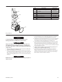
General Information
It is strongly recommended that on all vehicular installations
and on stationary engines subject to vibration, that hoses of the
specied diameter be used instead of rigid pipe connections to
the starter. Vehicle and engine vibration will soon loosen rigid
pipe connections, whereas hoses will absorb the vibration, and
connections will remain tight.
This starter is designed for ange mounting at the inlet. The
furnished Flange Mounting Kit is required for installation. All
piping, hoses and valving must be clean prior to installation. Make
sure that the starter inlet remains free of dirt and foreign material
during installation.
In the actual mounting of a starter, it may be best to have the
hose connections already made at the receiver and to have the
starter end of the hose handy for attaching to the starter.
Engine design often demands that the starter be mounted
underneath in extremely close quarters, and even though two of
the mounting bolt holes are easy to reach, the third one is often
less accessible. To install a starter, the following tools are required:
regular ratchet wrench, sockets, universal joint, socket extension
and a single or double-end box wrench.
The eciency of an Air Starter can be greatly impaired by an
improper hook-up. Hoses smaller than those recommended will
reduce the volume of air to the motor and the use of reducers
for piped-away applications in the exhaust port will restrict the
exhaust causing back pressure to the motor resulting in reduced
performance. The number of tees and elbows, and the length of
the supply line should be kept to a minimum. Use 1-1/2” hose or
pipe for supply lines up to 15 feet long; use 2” hose or pipe if the
supply line is over 15 feet long.
A leak in any of the connections in live air lines means that the
system will drain overnight and will have to be repressurized the
next morning by use of another vehicle or compressor. Make
your connections bubble tight to avoid unnecessary costs
and delays. On all threaded connections throughout the system,
use Ingersoll Rand No. SMB-441 Sealant, non-hardening No. 2
Permatex or Loctite®* Pipe Sealant.
After all connections have been made, check each joint with
a soap bubble test. There must be no leaks in live air lines. The
slightest leak will cause the system to lose pressure overnight.
Always run the air supply line from the side or top of the receiver,
never at or near the bottom. Moisture in the air collects at the
bottom of the receiver resulting in damage which could cause
the valves to become inoperative. Periodically open the petcock
at the bottom of the tank to drain the water.
7. Whenever a hazardous gas is being used to operate the starter,
there must be no leaks in inlet or exhaust piping or from any
other starter joints. All discharges should be piped away to a
safe area.
* Registered trademark of Loctite Corporation.
1.
2.
3.
4.
5.
6.
8. We recommend installation of a “glad hand” for emergency
re-pressurizing of the system. To keep the “glad hand” clean
and free of dirt, and to protect it from damage, a second “glad
hand” closed by a pipe plug can be mated to it, or a “glad hand”
protector bracket can be used.
9. It is required that a strainer be installed in the inlet line for each
starter.
Ingersoll Rand oers 5 strainers:
ST900-267-24 for 1-1/2 inch lines,
ST900-267-32 and ST900-267-32F for 2 inch lines,
ST900-267-48 for 3 inch lines and
ST900-267-64 for 4 inch lines.
These 300 mesh strainers provide 50 micron ltration and oer
signicant protection against supply line contaminates which
could damage the turbine components. Replacement elements
are:
ST900-266-24 for 1-1/2 inch,
ST900-266-32 for 2 inch pipe thread,
ST900-266-32F for 2 inch ange,
ST900-266-48 for 3 inch ange and
ST900-266-64 for 4 inch lines.
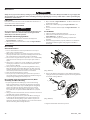
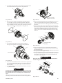
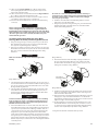
Orientation of the Starter
It is recommended that starters be ordered to proper orientation for
your specic mounting to the required engine or for your specic
installation. However, if the starter must be reoriented for installation,
proceed as follows:
Refer to the dimension illustration on page EN5, EN6 and EN7
and note that the Drive Housing can be located in any one of
sixteen radial positions relative to the Gear Case and the air inlet
can be located in any one of four radial positions relative to the
Drive Housing.
Study the engine mounting requirements, and determine the
required orientation of the Drive Housing relative to the Gear
Case. If the Drive Housing has to be reoriented, remove the eight
Drive Housing Cap Screws and rotate the Drive Housing to its
required position. Separation of the Drive Housing from the Gear
Case is not required. Reinstall the Drive Housing Cap Screws and
tighten to 28 ft-lb (38 Nm) torque.
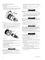
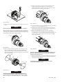
After the Drive Housing is properly oriented relative to the Gear
Case, determine if the inlet port will be favorably located for
hose installation. If either or both of these members must be
reoriented, use an 8 mm hex-head wrench to remove the four
motor housing cover cap screws, and rotate the motor housing
and/or motor housing cover to its desired position.
NOTICE
Do not separate the Motor Housing from the Intermediate Gear
case as gear lubrication oil will be lost.
Reinstall the motor housing cover cap screws and alternately tighten
them to 60 ft-lb (81.4 Nm) torque in 20 ft-lb (27 Nm) increments.
Mounting the Starter
Study the appropriate piping diagrams on page 8 through 11 and
install as indicated.
The air receiver tank for a starter installation must have a working
pressure rating equal to or greater than the maximum pressure at
which the starter will be operated.
1.
2.
3.
1.
2.
Placing the Starter in Service
Product Safety Information
Intended Use:
These air starters are intended for use in starting reciprocating internal combustion engines. These starters are designed to be
operated from a remote location after proper installation on the engine requiring starting.
For additional information refer to Air Starters for Internal Combustion Engines Product Safety Information Manual Form 45558624.
Manuals can be downloaded from ingersollrandproducts.com
EN

03537651_ed15 3
When connecting the starter to a receiver tank that is already in
service, bleed o the air pressure in the tank prior to installing
the starter.
WARNING
Bleed o the air pressure through a valve or petcock. Do not
remove a plug from the tank while the tank is still pressured.
Drain o any water that may have accumulated in the bottom of
the tank.
4. Using a 1-1/2” short nipple, install the SRV150 Starter Relay Valve
on the end of the receiver tank as shown in the piping diagram.
NOTICE
Make certain the connection is made to the inlet side of the Relay
Valve indicated by the word “IN”, cast on the valve body.
5. For air installations, install the Starter Control Valve (SMB-618)
on the dash panel (for vehicular installations) or some other
appropriate panel (for stationary installations). An optional
control circuit utilizing an electric solenoid control valve and a
panel mounted switch are available. Mount the 12V Solenoid
Valve (150BMP-1051B) securely and preferably in a vertical
position away from any concentration of heat, vibration or
contamination. Connect the leads to the operator’s starting
switch which should be located on the dashboard or control
panel.
6. Attach Starter Instruction Label (TA-STR-100) to the control panel
adjacent to the Starter Control Valve.
7. Mount the Air Pressure Gauge (150BMP-1064) on or adjacent to
the control panel. It should be located where it is readily visible to
the operator.
8. Connect the Starter Control Valve to the Relay Valve with 1/4”
hose. Install a tee in this line with a short feeder hose to the
Pressure Gauge.
NOTICE
Make certain the hose is connected to the supply side (marked
“SUP”) of the Starter Control Valve.
9. To determine the exact length of 1-1/2” air hose required, run
a piece of heavy duty hose or some other exible tubing of the
same diameter from the Relay Valve on the receiver to the starter
location on the engine.
10. Attach the 1-1/2” air hose to the outlet side of the Relay Valve, and
run the hose through the frame, etc. to its nal position at the
starter location.
11. At this point, determine whether or not it is feasible or practical
to attach the hose to the starter before or after the starter is
actually mounted. In many cases it may be necessary to attach
the hose to the starter before mounting.
12. If possible, liberally grease the teeth on the ring gear with a good
quality sticky gear grease. This will help promote the life of the
ring gear and the starter Pinion.
13. Move the starter into position, and mount it on the ywheel
housing. Tighten the mounting bolts to 100 ft-lb (136 Nm) torque.
3. 14. For Pre-Engaged Models, install a 1/4” hose line from the
delivery side (marked “DEL”) of the starter Control Valve or
Solenoid Valve to the “IN” port on the Starter Drive Housing.
NOTICE
Inadvertent application of air pressure to the “OUT” port will
result in Drive malfunction (Pinion will fail to retract). If this
condition occurs, loosen Drive Housing Cap Screws (38) to vent
Gear Case (28). Also, loosen Housing Plugs (10) and (11) to vent
Motor.
15. Install a 1/4” hose line from the “OUT” port on the Starter Drive
Housing to the small pipe tapped portion top of the Starter Relay
Valve or Solenoid Valve.
16. If the exhaust is to be piped away, remove the standard Splash
Deector which is located at the rear of the Housing Exhaust
Cover and replace the Assembly with the 1/4” N.P.T. pipe plug
supplied with the starter.
17. Pressurize the complete starting system and check every
connection with a soap bubble test. There must be no leaks in
live air lines or other connections.
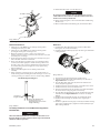
Barring Over the Engine
Occasionally, for setting injectors and/or for timing purposes, it may
be desirable to bar over the engine in such a manner that any given
piston can be stopped at any given location. This is very easily done
with a Series ST700 Turbine Starter. Remove the Deector Retaining
Screw (5), the Deector Return Spring (4) and the Splash
Deector (3). If piped-away exhaust is being used, remove piping
so that you can gain access to the hole at the center of the Housing
Exhaust Cover. Remove the 1/4” pipe plug.
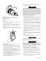
For Models with Inertia Drive:
Manually engage pinion and insert a 1/4” hex wrench through the
hole in the Housing Cover to engage the hex drive recess at the
rear of the Motor Assembly.
Manually rotate the Motor Assembly until the engine is cranked to
the desired position.
For Models with Pre-Engaged Drive
Disconnect the 1/4” hose at the “OUT” port on the Drive Housing,
and plug the hole in the Drive Housing with a 1/4” pipe plug.
Engage the Drive Pinion with the ywheel by applying a
minimum of 70 psig (4.8 bar/483 kPa) to the “IN” port on the Drive
Housing.
Insert a 1/4” hex wrench through the hole in the Housing Exhaust
Cover to engage the hex drive recess in the rear of the Motor
Assembly.
Manually rotate the Motor Assembly until the engine is cranked to
the desired position.
1.
2.
1.
2.
3.
4.
EN

4 03537651_ed15
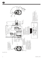
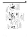
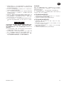
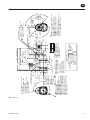
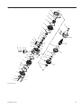
ST700 Inertia Mounting Dimensions
1/4” Pipe Plug in Housing Inlet Boss
can be removed and Gage installed to
check supply pressure to Starter.
Before re-installing Plug, clean
threads and apply Pipe Thread Sealant
(IR No. SMB-441 or Equivalent)
to prevent leakage.
Standard Inlet Flange Kit ST700-K166
(Includes Mounting Hardware)
To Splash Deector ( During Operation)
441.98
(17.40”)
425.98
(16.77”)
69.80
(2.75”)
158.28
(6.23”)
117.00
(4.61”)
86.00
(3.39”)
175.00
(6.89”)
“2”
“3”
“1”
Ø 193.00
“0”
Cover
Motor Housing
Splash Deector
Ø 134.00
(5.28”)
Over ST700-166
Flange
35.70
(1.41”)
Inlet Boss
130.30
(5.13”)
317.50
(12.50”)
117.20
(6.98”)
85.85
(3.38”)
R71.00
(2.80”)
85.73
(3.38”)
Oset
Gear
Case
Drive
Housing
Intermediate Gear Case
22.35 Mesh
(.88”)
Ring Gear Face
Ø 152.00
(5.98”)
46.00
(1.81”)
50.80
(2.00”)
Ø 92.01
(3.62”)
Pilot
114.20
(4.50”)
9.65
(.38”)
12.70
(.50”)
1/2”-13 UNC
19.1 Deep-4 Places
(.75)
Ø 1.50” Type J518C
Flange
4.8 mm Hex. Head Bolts, allow
rotation of Inlet in 4 positions.
When changing Inlet Orientation
do not rotate Intermediate Gear Case.
Intermediate Gear Case is timed with
the Oset Gear Case.
4” NPT for Piped Exhaust
when using Piped Exhaust, replace
Splash Deector assembly with
Pipe Plug supplied with Starter.
** For Natural Gas Operation, 4” NTP
threads must be sealed. Use Pipe Thread
Sealant (IR No. SMB-441 or equivalent) to
prevent gas leakage.
** For Natural Gas Operation, Piped Exhaust
must be used and drive housing vent plug
replaced with suitable hose which connects
into piped exhaust system. To be sealed with
thread sealant (IR No. SMB-441) or equivalent.
1. The Splash Deector assembly must be
removed for accessing the 1/4” hole drive
barring hole or with installing a Pipe away exhaust.
2. Before removing the Hex. Plug the Starter must
be resonably level to prevent draining the oil
from the Gear Case.
3. When the Hex. Plug is removed a slight amount
of oil may leak from the hole. (This is normal.)
4. Before reassembly clean all oil from the threads
and apply pipe thread sealant (IR No. SMB-441 or
equivalent) to prevent oil leakage.
Ø 137.50
(5.41”)
Ø 16.7
(.66”)
3-Places
7° 30’
120°
Typ.
R 73.15
(2.88”)
Ref. Hole for
Orientation Code.
Left Hand
Rotation
H
J
I
K
L
M
N
O
P
A
B
C
D
E
F
G
Right Hand
Rotation
Notes:
1. Starter should be installed on the enigne with
the exhaust pointed down.
2. These models are not approved for applications
Where the starter is exposed to the transmission uid.
3. Drive housing orientation code is based on position
of mounting hole opposite the pinion opening.
4. Standard orientation shown on 6/5/89 be shipped unless
otherwise specied.
5. Please read the instructions before attempting
to reorient.
6. Starter weight = 68 lbs (30.8 Kg)
- MODEL CODING -
Size Starter
Orientation Code
Inlet
Type of Drive Flange
Type of Drive Housing
Type Gear Case
Gear Ratio
Pinion
Drive Housing
Drive
ST7 50 G B D I 03 R 31 - 0 N
Gas Operation
Percent Arc
Rotation
Orientation Options
Inlet
4 @ 90° 16 @ 22 1/2°
Drive Housing
(Dwg. TPA1276-4)
EN

03537651_ed15 5
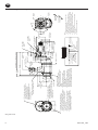
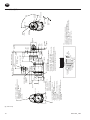
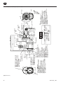
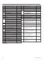
Mounting Dimensions
Notes:
1. Drive housing orientation code is based on position
of control ports.
2. Starter orientation illustrated is “OG”. If not specied
when ordering orientation “OG” will be shipped.
3. Starter weight = 69 lbs (31.3 Kg) without Inlet Flange.
4. When ordering Starter, include model number and
orientation code number.
5. Information concerning models not listed should be
requested from Ingersoll Rand “Engine Starting Systems”
marketing department.
6. Orientation code based on Starter Gear Case positioned
as shown.
- MODEL CODING -
Size Starter
Orientation Code
Inlet
Type of Drive Flange
Type of Drive Housing
Type Gear Case
Gear Ratio
Pinion
Drive Housing
Drive
ST7 50 G B D P 03 R 31 - 0 G
Gas Operation
Percent Arc
Rotation
Orientation Options
Motor
Housing
4 @ 90° 16 @ 22 1/2°
Drive
Housing
4” NPT for Piped Exhaust
when using Piped Exhaust, replace
Splash Deector Assembly with
Pipe Plug Supplied with Starter.
H
** For Natural Gas Operation, 4” NTP
Threads must be Sealed. Use Pipe Thread
Sealant (IR No. SMB-441) or equivalent to
prevent gas leakage.
** For Natural Gas Operation, Piped Exhaust
must be used and Drive Housing Vent Plug
replaced with suitable Hose which connects
into Piped Exhaust System. Threaded connections
To be sealed with thread sealant (IR No. SMB-441)
or equivalent.
4.8 mm Hex. Head Bolts, allow
rotation of Inlet in 4 positions.
When changing Inlet Orientation
do not rotate Intermediate Gear Case.
Intermediate Gear Case is timed with
the oset Gear Case.
For access to 1/4” Hex. Drive Barring
Hole in Rotor Shaft, or when Installing Piped
Exhaust, the Splash Deector Assembly must
be removed.
Before removing assembly, make certain the
Starter is reasonably level to prevent draining
of oil from the Gear Case. (When the Deector
Screw is removed, a slight amount of oil may leak
from hole; this is normal) before reassembly of the
Splash Deector, or when installing 1/4” Pipe Plug
when using Pipe Exhaust, clean all oil from the threads
and apply Pipe Thread Sealant (IR No. SMB-441
or Equivalent) to prevent oil leakage.
H
1/4” Pipe Plug in Housing Inlet Boss
can be removed and Gage installed to
check supply pressure to Starter.
Before re-installing Plug, clean
threads and apply Pipe Thread Sealant
(IR No. SMB-441 or Equivalent)
to prevent leakage.
To Splash Deector ( During Operation)
472.28
(18.59”)
363.80
(14.32”)
69.80
(2.75”)
35.70
(1.41”)
223.50
(8.80”)
138.50
(5.45”)
10.00
(.39”)
23.00
(.91”)
R76.00
(2.99”)
R71.00
(2.80”)
85.73
(3.38”)
50.80
(2.00”)
58.34
(2.30”)
160.50
(6.32”)
18.50
(.73”)
28.50
(1.13”)
Pinion Travel
7° 30’
91.98
(3.62”)
Pilot Dia.
R 73.00
(2.87”)
Ø 137.50
(5.41”)
“3”
“1”
“2”
488.28
(19.22”)
H
H
1/2”-13 UNC Thread
.75” Deep-4 Places
Ø 1.50” Type J518C
Flange
Standard Inlet Flange Kit ST700-K166
(Includes Mounting Hardware)
Inlet Position “0” thru “3”
(#0 Shown)
Oset
Gear Case
Inlet Boss
Motor Housing
Splash Deector
Exhaust Cover
Intermediate Gear Case
158.28
(6.23”)
117.00
(4.61”)
175.00
(6.89”)
“2”
“1”
“0”
“3”
86.00
(3.39”)
Ø 134.00
(5.28”)
Over ST700-166
Flange
Drive Housing
Drive Housing Vent Plug **
1/4” NPT Control Port for
Engaging Pinion.
Operating Pressure = 70 to 150 P.S.I.G
(483 to 1034 kPa)
1/4” NPT Control Port for Actuation
of main Air Supply to Starter Motor.
Operating Pressure = 70 to 150 P.S.I.G
(483 to 1034 kPa)
1/8” NPT
H
H
H
Flywheel Face
Angle “A” thru “P”
(Angle “G” shown)
Control Ports
120°
Typ.
Ø (.65”)16.60
Holes Mounting Unit;3
Holes; SAE 3 Flange
16 holes equally spaced
permit Drive Housing to
rotate 16 positions on
Gear Case
Left Hand
Rotation
Right Hand
Rotation
“H”
“J”
“I”
“K”
“L”
“M”
“N”
“O”
“P”
“A”
“B”
“C”
“D”
“E”
“F”
“G”
(Dwg. TPA1277-5)
EN

6 03537651_ed15
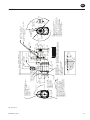
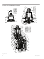
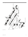
ST700 Pre-Engaged Mounting Dimensions
1/4” Pipe Plug in Housing Inlet Boss
can be removed and Gage installed to
check supply pressure to Starter.
before re-installing Plug, clean
threads and apply Pipe Thread Sealant
(IR No. SMB-441 or Equivalent)
to prevent leakage.
Standard Inlet Flange Kit ST700-K166
(Includes Mounting Hardware)
4.8 mm Hex. Head Bolts, allow
rotation of Inlet in 4 positions.
When changing Inlet Orientation
do not rotate Intermediate Gear Case.
Intermediate Gear Case is timed with
the oset Gear Case.
4” NPT for Piped Exhaust
Splash Deector assembly must be
removed and pipe plug must be installed
in Exhaust Cover hole when using Pipe
Exhaust.
** For Natural Gas Oper
ation, 4” NTP
threads must be seale
d. Use Pipe Thread
Sealant (IR No. SMB-44
1 or equivalent) to
prevent gas leakag
e.
** For Natural Gas Operation, Piped Exhaust
must be used and Drive Housing Vent Plug
replaced with suitable Hose which connects
into Piped Exhaust System. To be sealed with
Thread Sealant (IR No. SMB-441) or equivalent.
1. The Splash Deector assembly must be
removed for accessing the 1/4” hole Drive
Barring hole or with installing a Pipe away exhaust.
2. Before removing the Hex. Plug the Starter must
be resonably level to prevent draining the oil
from the Gear Case.
3. When the Hex. Plug is removed a slight amount
of oil may leak from the hole. (This is normal.)
4. Before reassembly clean all oil from the threads
and apply pipe thread sealant (IR No. SMB-441 or
equivalent) to prevent oil leakage.
Notes:
1. Starter should be installed on the enigne with
the Exhaust pointed down.
2. These models are not approved f
or applications
where the starter is exposed to the Transmission Fluid.
3. Drive Housing Orientation code is based on position
of mounting hole opposite the Pinion Opening.
4. Standard Orientation shown (OE) be shipped unless
otherwise specied.
5. Please read the instructions before attempting
to reorient.
6. Starter weight = 98 lbs (44.5 Kg)
- MODEL CODING -
Size Starter
Orientation Code
Inlet
Type of Drive Flange
Type of Drive Housing
Type Gear Case
Gear Ratio
Pinion
Drive Housing
Drive
ST7 50 G D D P 09 R 51 - 0 E
Gas Operation
Percent Arc
Rotation
Orientation Options
Inlet
4 @ 90° 16 @ 22 1/2°
Drive Housing
158.28
(6.23”)
“2”
“3”
“1”
175.00
(6.89”)
“0”
Over ST700-166
Flange
117.00
(4.61”)
86.00
(3.39”)
Ø 134.00
(5.28”)
69.80
(2.75”)
35.70
(1.41”)
Ø 196.0
(7.72”)
Drive Housing Vent
Plug 1/8” NPT
Ø 152.35 Pilot
(6.00”)
1/4 - 18 NPT
Control Port
Outlet
Control
Ports
1/4 - 18 NPT
Control Port
Outlet
R 89.00
(3.50”)
99.00
(3.50”)
20.00
(.79”)
81.00
(3.19”)
102.00
(4.02”)
195.00
(7.70”)
186.50
(7.34”)
180.00
(7.09”)
Flywheel Face
Drive Housing
168.00
(6.61”)
33.00
(1.30”)
20.00
(.79”)
306.29
(12.06”)
414.78
(16.33”)
Cover
Motor Housing
Splash Deector
Inlet
Boss
Ø 1.50”
Type J518C
Flange
5/16”- UNC
(.75) Deep-4 Places
To Splash Deector ( During Operation)
430.78
(16.96”)
Oset
Gear
Case
Intermediate Gear Case
41.50
(1.63”)
Pinion
Travel
Ø 180.00
(7.09”)
Ø 228.60
(9.00”)
45°
90° Typ.
Left Hand
Rotation
H
J
I
K
L
M
N
O
P
A
B
C
D
E
F
G
Right Hand
Rotation
(Dwg. TPA1278-4)
EN

03537651_ed15 7
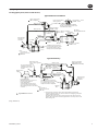
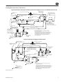
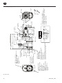
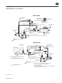
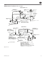
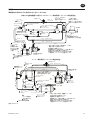
Piping Diagrams
Pre-Engaged System (Series ST700 Shown)
Typical Stationary
Typical Vehicular Installation
1/4” NPT pressure measuring
port. Operating pressure not to
exceed max. pressure rating
stamped on starter nameplate.
Exhaust
Inlet Flange Kit
ST700 - K166
Inlet Flange Kit
ST700 - K166
Relay Valve 1½”
SRV150
Relay Valve 1½”
SRV150
Drain Valve 1/2” N.P.T.
150BMP - 1067
Check Valve
150BMP - 1056
JIC 37° Adaptor 1/4” N.P.T.
SS350 - MC4
JIC 37° Adapter
1½” N.P.T.
Air Pressure Gage
150BMP - 1064L
Air
Receiver
Tank
Air Supply
from dry Air Brake Tan
k
“Optional Control Circuit Utilizing
Electric Solenoid Control Valve and
Panel Mounted Switch.”
Solenoid Valve - 12 volt
150BMP - 1051B
Starter Control Valve
SMB-618 (Brass/Air)
SMBG-618 (Chrome/Gas)
Drive Housing
Vent Plug **
1/8” N.P.T.
(2) Leads to Operators
Starting Switch.
Starter Control Valve
SMB - 618 (Brass)
#4 Hose (1/4”)
#4 Hose (1/4”)
#4 Hose (1/4”)
#4 Hose (1/4”)
1½” Hose
Exhaust *
Air Pressure Gage
150BMP - 1064L (Air Only)
Relief valve set at
15 P.S.I. above regulator
setting
High Pressure
Supply
Pressure Regulator
(Maximum setting not to exceed
pressure rating shown on
Starter Nameplate)
Standard high pressure system
air or gas. Use pressure regulator
when supply pressure is over rating
of starter
Ingersoll Rand Part Number
* * For natural gas operation, starter main exhaust must be piped away.
To pipe the drive housing vent, remove the drive housing plug and replace
it with a suitable tubing line.
The tubing must vent at a safe location and must not be interconnected
with any other exhaust lines which might introduce a back pressure on the
drive housing vent.
1/4” N.T.P. pressure measuring
port. Operating pressure not to
exceed max. pressure rating
stamped on starter nameplate.
For gas operation, the
relief valve outlet must
be piped away to a safe
location
JIC 37° Adaptor 1/4” N.P.T.
SS350 - MC4
1 ½” N.P.T.
1½” Pipe
Drive Housing
Vent Plug **
1/8” N.P.T.
Note:
Use Sealant on
all pipe connections.
SMB - 441
#4 Hose (1/4”)
1½” Hose
Note:
Use Sealant on
all pipe connections.
SMB - 441
(Dwg. TPA1282-3)
EN

8 03537651_ed15
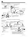
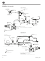
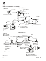
Piping Diagrams
Inertia Type System (Series ST700 Shown)
PIPING DIAGRAM FOR A TYPICAL VECHICULAR INSTALLATION-INERTIA
(2) LEADS TO OPERATORS
STARTING SWITCH.
SOLENOID VALVE - 12 VOLT
150BMP-1051B
“OPTIONAL CONTROL CIRCUT UTILIZING
ELECTRIC SOLENOID CONTROL VALVE AND
PANEL MOUNTED SWITCH.”
STARTER CONTROL VALVE
SMB-618(BRASS)
#4 HOSE (1/4”)
AIR PRESSURE GAUGE
150BMP-1064L
JIC 37º ADAPTER
1½" N.P.T.
JIC 37º ADAPTOR 1/4” N.P.T.
SS350-MC4
AIR SUPPLY FROM
DRY AIR BRAKE TANK
CHECK VALVE
150BMP-1056
1½" HOSE
INLET FLANGE KIT
ST700-K166
1½" N.P.T.
NOTE :
USE SEALANT
ON ALL PIPE
CONNECTIONS.
SMB-441
AIR
RECEIVER
TANK
RELAY VALVE 1½"
SRV150
1½"PIPE DRAIN VALVE 1/2” N.P.T.
150BMP-1067
1/4" N.P.T. PRESSURE MEASURING PORT.
OPERATING PRESSURE NOT TO EXCEED
MAX. PRESSURE RATING STAMPED ON
NAMEPLATE.
EXHAUST
PIPING DIAGRAM FOR A TYPICAL STATIONARY INSTALLATION-INERTIA
RELIEF VALVE
SET AT 15 P.S.I.
ABOVE REGULATOR
SETTING
FOR GAS OPERATION, THE
RELIEF VALVE OUTLET MUST
BE PIPED AWAY TO A
SAFE LOCATION.
HIGH PRESSURE
SUPPLY
#4 HOSE (1/4”)
AIR PRESSURE GAUGE
150BMP-1064L (AIR ONLY)
1½" HOSE
#4 HOSE (1/4”)
JIC 37° ADAPTOR 1/4” N.P.T.
SS350-MC4
NOTE :
USE SEALANT
ON ALL PIPE
CONNECTIONS.
SMB-441
RELAY VALVE 1½"
SRV150
INLET FLANGE KIT
ST700-K166
STARTER CONTROL VALVE
SMB-618 (BRASS/AIR)
SMBG-618 (CHROME/GAS)
EXHAUST
1/4" N.P.T. PRESSURE MEASURING PORT.
OPERATING PRESSURE NOT TO EXCEED
MAX. PRESSURE RATING STAMPED ON
NAMEPLATE.
INGERSOLL-RAND PART NUMBER
PRESSURE REGULATOR
(MAXIMUMSETTING NOT TO EXCEED
PRESSURE RATING SHOWN ON
STARTER NAMEPLATE)
FOR NATURAL GAS OPERATION, STARTER MAIN EXHUST MUST BE PIPED AWAY.
TO PIPE THE DRIVE HOUSING VENT, REMOVE THE DRIVE HOUSING
PLUG AND REPLACE IT WITH A SUITABLE TUBING LINE.
THE TUBING MUST VENT AT A SAFE LOCATION AND MUST NOT BE
INTERCONNECTED WITH ANY OTHER EXHAUST LINES WHICH
MIGHT INTRODUCE A BACK PRESSURE ON THE DRIVE HOUSING VENT.
#4 HOSE (1/4”)
(Dwg. TPA1283-3)
EN

03537651_ed15 9
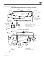
Piping Diagrams
Pre-Engaged System (Series ST700 Shown)
Typical Installation with Engine Prelube System
Typical Installation with Engine Prelube System when Supply Pressure is over Rated Starter Pressure
Relay Valve 1½”
SRV150
Drive Housing
Vent Plug **
1/8” N.P.T.
Ingersoll Rand Part Number
* * For natural gas operation, starter main exhaust
must be piped away.
To pipe the drive housing vent, remove the drive
housing plug and replace it with a suitable tubing line.
The tubing must vent at a safe location and must
not be interconnected with any other exhaust lines
which might introduce a back pressure on the
drive housing vent.
Note:
Use Sealant on
all pipe connections.
SMB - 441
1/4” NPT pressure measuring
port. Operating pressure not to
exceed max. pressure rating
stamped on starter nameplate.
1/4” N.P.T. Pressure
Measuring Port.
Operating pressure
not to exceed max.
pressure rating stamped
on starter nameplate.
Inlet Flange Kit
ST700 - K166
Relay Valve 1½”
SRV150
Drain Valve 1/2” N.P.T.
150BMP - 1067
Check Valve
150BMP - 1056
JIC 37° Adaptor 1/4” N.P.T.
SS350 - MC4
JIC 37° Adapter
1½” N.P.T.
JIC 37° Adaptor
1½” N.P.T.
Air Pressure Gage
150BMP - 1064L (Air Only)
Air
Receiver
Tank
Air Supply
from dry Air Brake Tank.
Starter Control Valve
SMB - 618 (Brass)
#4 Hose
#4 Hose (1/4”)
#4 Hose (1/4”)
#4 Hose (1/4”)
#4 Hose (1/4”)
#4 Hose (1/4”)
1 ½” Hose
1 ½” N.P.T.
1½” Pipe
1½” Pipe
Note:
Use Sealant on
all pipe connections.
SMB - 441
#4 Hose
1½” Pipe
Inlet Flange Kit
ST700 - K166
Starter Control Valve
SMB-618 (Brass/Air)
SMBG-618 (Chrome/Gas)
Drive Housing
Vent Plug **
1/8” N.P.T.
#4 Hose (1/4”)
1½” Hose
Exhaust *
Exhaust *
Air Pressure Gage
150BMP - 1064L
(Air Only)
To Prelube
Pump
Relief valve set at
15 P.S.I. above
regulator setting
High Pressure Supply
Pressure Regulator
(Maximum setting not to
exceed pressure rating
shown on Starter Nameplate)
Oil Pressure Sensing Valve
Oil Pressure Sensing Valve
For gas operation, the
relief valve outlet must
be piped away to a safe
location.
JIC 37° Adaptor 1/4” N.P.T.
SS350 - MC4
JIC 37° Adaptor 1/4” N.P.T.
SS350 - MC4
(Dwg. TPA1281-3)
EN

10 03537651_ed15
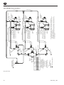
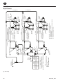
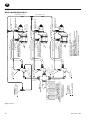
Piping Diagrams
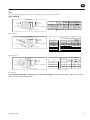
Typical Multiple Starter Installation
1/4” NPT pressure measuring
port. Operating pressure not to
exceed max. pressure rating
stamped on starter nameplate.
1/4” NPT pressure measuring
port. Operating pressure not to
exceed max. pressure rating
stamped on star
ter nameplate.
1/4” NPT pressure measuring
port. Operating pressure not to
exceed max. pressure rating
stamped on starter nameplate.
Pipe Size
See Chart
Inlet Flange Kit
ST700 - K166
Typical
Relay Valve 1½”
SRV150
Relay Valve 1½”
SRV150
Relay Valve 1½”
SRV150
JIC 37° Adaptor
1½” N.P.T.
JIC 37° Adaptor
1½” N.P.T.
JIC 37° Adaptor
1½” N.P.T.
Starter Control Valve
SMB-618 (Brass/Air)
SMBG-618 (Chrome/Gas)
Drive Housing
Vent Plug **
1/8” N.P.T.
Drive Housing
Vent Plug **
1/8” N.P.T.
Drive Housing
Vent Plug **
1/8” N.P.T.
#4 Hose (1/4”)
#4 Hose (1/4”)
#4 Hose (1/4”)
#4 Hose (1/4”)
1½” Hose
Exhaust
*
Exhaust *
Exhaust *
Ingersoll Rand Part Number
* * For natural gas operation, starter main exhaust must be piped away.
To
pipe the drive housing vent, remove the drive housing plug and replac
e
it with a suitable tubing line.
The tubing must vent at a safe location and must not be interconnected
with an
y other exhaust lines which might introduce a back pressure on the
drive housing vent.
JIC 37° Adaptor 1/4” N.P.T.
SS350 - MC4
JIC 37° Adaptor 1/4” N.P.T.
SS350 - MC
4
JIC 37° Adaptor 1/4” N.P.T.
SS350 - MC4
JIC 37° Adaptor 1/4” N.P.T.
SS350 - MC4
JIC 37° Adaptor 1/4” N.P.T.
SS350 - MC4
JIC 37° Adaptor 1/4” N.P.T.
SS350 - MC4
1½” Pipe
1½” Pipe
No. Starters
2 2-1/2”
3-1/2”
3-1/2”
3-1/2”
3”
4
4
3
3
4
5
ST750
150 PSIG
Min. Pipe Size
Supply must be adequate to
maintain desired operating
pressures at the starters with
starters runnning. (Not to exceed
max. pressure shown on
starter nameplate.)
ST700 series multiple
starter piping schematic
showing the control circuit.
ST799
90 PSIG
Min. Pipe Size
#4 Hose (1/4”)
#4 Hose (1/4”)
1½” Hose
1½” Hose
Note:
Use Sealant on
all pipe connections.
SMB - 441
(Dwg. TPA1284-4)
EN

03537651_ed15 11
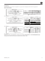
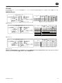
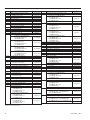
Product Information
Intended Use:
Series ST700 Turbine Powered Starters are designed for air or gas operation in o-highway, marine and stationary applications.
How to order a Starter
- MODEL CODING -
Size Starter
Orientation Code
Inlet
Type Mounting Flange
Type of Drive Housing
Type Gear Case
Gear Ratio: B=2.18-1
Pinion
(See Table of
Pinion Data)
Drive Housing
Model
Orientation
Code
Drive
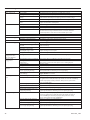
IR No.
Pinion Data
No.of
Teeth
D.P.
P.D.
PA
H
ST750GBDI03R31
150/1034
20BM-299-1
Must be specied when ordering
12/12 6/8 2.00” 20°
20°
20°
20°
2.00”
2.00”
2.00”
6/8
6/8
6/8
12/12
12/12
12/12
20BM-299-3
20BM-299-1
20BM-299-3
150/1034
90/621
90/621
ST750GBDI03L32
ST799GBDI03R31
ST799GBDI03L32
Drive
ST7 50 G B D I 03 R 31 - 0 N
Gas Operation
Percent Arc
Rotation
Supply
Pressure
PSIG/Kpa
Max.
*
(Dwg. TPD1176)
- MODEL CODING -
Size Starter
Orientation Code
Inlet
Type Mounting Flange
Type of Drive Housing
Type Gear Case
B=2.18-1
C=2.53-1
Pinion
(See Table of
Pinion Data)
Drive Housing
Drive
ST7 50 G B D P 03 R 31 - 0 G
Gas Operation
Percent Arc
Rotation
Gear Ratio:
Must be specied when ordering
Model
Pinion Data
No.of
Teeth
D.P.
P.D.
PA
H
ST750GBDP03R31
150/1034
12/12 6/8 2.00” 20°
20°
20°
20°
2.00”
2.00”
2.00”
6/8
6/8
6/8
12/12
12/12
12/12
150/1034
90/621
90/621
ST750GBDP03L32
ST750GCDP03R25
ST750GBDP03L26
Supply
Pressure
PSIG/Kpa
Max.
*
Orientation Code
ST799GBDP03R31 12/12 6/8 2.00” 20°
20°
20°
20°
2.00”
2.00”
2.00”
6/8
6/8
6/8
12/12
12/12
12/12
150/1034
150/1034
90/621
90/621
ST799GBDP03L32
ST799GCDP03R25
ST799GBDP03L26
(Dwg. TPD1177)
- MODEL CODING -
Size Starter
Orientation Code
Inlet
Type Mounting Flange
Type of Drive Housing
Type Gear Case
Pinion
(See Table of
Pinion Data)
Drive Housing
Drive
ST7 50 G D D P 09 R 51 - 0 E
Gas Operation
Percent Arc
Rotation
Gear Ratio: D=3.44-1
Must be specied when ordering
Model
Pinion Data
No.of
Teeth
D.P.
P.D.
PA
H
ST750GDDP09R51
150/1034
15 6/8 2.50” 20°
20°
20°
2.50”
2.50”
6/8
6/8
15
15
150/1034
90/621
ST750GDDP09L52
ST799GDDP09R51
Supply
Pressure
PSIG/Kpa
Max.
*
Orientation
Code
(Dwg. TPD1178)
For dierent models or special applications, contact your nearest Ingersoll Rand Distributor or SALES HEADQUARTERS, Engine
Starting Systems, P.O. Box 1776, Liberty Corner, NJ 07938, Phone (908) 647 - 6000.
EN

12 03537651_ed15
安装
注 意
为获得最大性能,请在安装或操作 ST700 系列涡轮电力起动器
(Series ST700 Turbine-Powered Starters) 之前阅读本手册。
一般信息
强烈建议在受到振动的所有车载装置和固定发动机上,应该使
用指定的软管而非刚性管来连接至起动器。 车辆和发动机振
动会很快松动刚性管连结,而软管会缓冲此振动,从而使连
结保持紧固。
该起动器供在进口处的法兰装置之用。 在安装时需要提供的法
兰装置套件。 在安装前,必须清洁所有管道、软管和装设阀
门。 在安装期间,请确保起动器进口没有污物和异物。
在实际安装起动器的过程中,最好已在接收器中连接软管,并
使软管的起动器末端便于连接到起动器。
通常,发动机设计要求起动器应安装在向下近四分之一处,而
且虽然其中两个装配螺栓孔易于触及,但是第三个孔却常常难
以触到。 要安装起动器,需要以下工具: 常用的棘轮扳手、
套筒、万向接头、伸缩套筒和单头或双头套筒扳手。
连结不当会大大削减气动起动器的效率。 使用小于所建议尺
寸的软管将会使进入马达中的压缩空气量减少,而且使用在排
气管端口内的排放装置(即渐缩管)将会限制排气(对导致
性能降低的发动机造成反压力)。 三通和弯头的数量以及供
应管线的长度都应最小化。 如果供应管线长达 15 英尺,可使
用 1-1/2”软管或管道;如果供应管线超过 15 英尺,可使用
2”软管或管道。
活动空气管道中的任何连接装置出现泄漏状况都表明,系统
将会整夜排放并必须在第二天早上通过使用另一台车辆或压
缩机来增压。 使连接气泡紧密以避免不必要的费用和延迟。
在整个系统的所有螺纹连接装置上,使用 Ingersoll Rand No.
SMB-441 Sealant、非硬化的 No. 2 Permatex 或 Loctite®* Pipe
Sealant。
在进行所有连接后,可使用肥皂气泡测试检查每个接头。 在
活动空气管道中一定不能出现泄漏状况。 稍有泄漏便会导致
系统很快失压。 务必从接收器的侧面或顶部运行空气供应管
线,切勿在底部或底部附近运行。 空气中的水分聚集在接收
器的底部,便可能导致阀门损坏以致无法使用。 定时打开箱
底部的小龙头以排出水份。
7. 无论何时使用危险气体来操作起动器,都必须确保进口或排出
管道或任何其他起动器的接头处不会出现泄漏状况。 应将所
有排出物排放到安全地方。
8. 对于系统的紧急增压,我们建议使用“glad hand”安装。 要
保持“glad hand”干净和没有污物,并保护其免受损坏,可
将其连接到由管道塞子密封的第二个“glad hand”,或可使
用“glad hand”保护器托架。
9. 需要在每个起动器的进口管线中安装滤水器。
Ingersoll Rand 提供 5 个滤水器:
ST900-267-24(1-1/2 英寸管线),
ST900-267-32 和 ST900-267-32F(2 英寸管线),
ST900-267-48(3 英寸管线)和
ST900-267-64(4 英寸管线)。
该 300 网滤水器具有 50 微米滤芯,可有效保护供应管线免受
污染(这可能会损坏涡轮组件)。 更换元件有:
ST900-266-24(1-1/2 英寸),
ST900-266-32(2 英寸管螺纹),
ST900-266-32F(2 英寸法兰),
ST900-266-48(3 英寸法兰)和
ST900-266-64(4 英寸管线)。
* Loctite Corporation 的注册商标。
1.
2.
3.
4.
5.
6.
起动器的定向
建议起动器应该根据所需发动机的特殊装置或特殊设备进行正确
定向。 但是,如果起动器因安装而必须重新定向,可按照以下
步骤操作:
请参阅第 EN5、EN6 和 EN7 页的尺寸图示,另请注意,传动箱
可位于与齿轮箱相对的 16 个径向位置中的任一处,并且空气
进口阀可位于与传动箱相对的 4 个径向位置中的任一处。
学习发动机安装要求,并确定与齿轮箱相对的传动箱的所需
定向。 如果传动箱必须重新定位,可卸下 8 个传动箱有头螺
丝,然后将传动箱旋转至所需位置。 不需要分开齿轮箱和传
动箱。 重新安装传动箱有头螺丝,并旋紧至 28 英尺-磅(38
牛米)扭矩。
在传动箱正确定向(相对于齿轮箱)之后,请确定进气口是否
有利于软管安装。 如果以上任意一个或两个装置都必须重新定
向,可使用 8 mm 六角扳手卸下 4 个电动机外壳盖有头螺丝,
然后将马达外壳和/或马达外壳盖旋转至所需位置。
注 意
由于齿轮滑润油将会损耗,因此不可分开马达外壳和中间的齿
轮箱。
重新安装马达外壳盖有头螺丝,并以 20 英寸-磅(27 牛米)为增
量交替地将其旋紧至 60 英寸-磅(81.4 牛米)扭矩。
安装起动器
学习第 8 至 11 页的相应管道布置图,并根据指示进行安装。
起动器装置的空气接收箱必须具有工作压力(等于或大于起动
器将会操作的最大压力)。
将起动器连接到已在使用的接收箱时,可在安装起动器之前排
出箱中的气压。
警 告
通过阀或旋塞排出气压。 当储气罐仍处于增压状态时,切勿从箱
上拔下塞子。
排出积聚在箱底部的水份。
4. 使用 1-1/2” 的短螺纹接套将 SRV150 起动器主启动阀安装在储
气罐末端,如管道布置图所示。
注 意
确保连接到主启动阀的进口侧(用字母“IN”表示),并确保连接
到阀座。
5. 对于通风装置,可在仪表板上(车载装置)或某些其他相应面
板上(固定装置)安装起动器控制阀 (SMB-618)。 可以使用利
用电磁控制阀的可选控制电路和和安装在面板上的开关。 最
好以垂直位置(远离集中热能、振动或污染的地方)安全地安
装 12V 电磁阀 (150BMP-1051B)。 将导线连接到操作者的起动
开关(应位于仪表板或控制面板上)。
6. 将起动器说明标签 (TA-STR-100) 贴在邻近起动器阀的控制面板
上。
7. 将压力表 (150BMP-1064) 安装在控制面板上或邻近控制面板
处。 它应位于操作者容易看到的地方。
8. 将起动器控制阀连接到具有 1/4” 软管的继动阀上。 使用短
软管将此管道中的 三通管安装到压力计上。
注 意
确保将软管连接到起动器控制阀的电源侧(标为“SUP”)。
1.
2.
3.
1.
2.
3.
使起动器处于使用状态
产品安全信息
用途:
此类空气启动器应用于往复式内燃机的启动。此类启动器应在正确安装到需要启动的内燃机上后,进行远程操作。
更多信息请参见内燃机空气启动器产品安全信息手册表 45558624。
手册可从 www.irtools.com 下载。
ZH

03537651_ed15 13
9. 要确定所需的 1-1/2” 进气软管的确切长度,可重负荷运行软
管设备或直径相同的某些其他挠性软管(从储气罐的主启动阀
到发动机的起动器位置)。
10. 将 1-1/2”进气软管连接到主启动阀的出口侧,并使软管从机
架等穿过起动器处的最终位置。
11. 在此,可在实际安装起动器之前或之后,确定将软管连接到起
动器是否可行或实用。在多数情况下,可能需要在安装之前将
软管连接到起动器。
12. 如果可能,请使用优质粘性齿轮润滑油充分润滑环形齿轮上的
齿轮。这将有助于延长环形齿轮和起动器小齿轮的寿命。
13. 将起动器各就其位,然后将其安装在飞轮壳上。 旋紧安装螺
栓至 100 英寸-磅(136 牛米)扭矩。
14. 对于预先安装的型号,可从起动器控制阀或电磁阀的出料侧
(标为“DEL”) 到起动器传动箱的“IN”端口安装 1/4” 软管管
线。
注 意
不小心将气压应用到“OUT”端口将会导致传动发生故障(小齿
轮将无法缩进)。 如果发生此种情况,可旋松传动箱有头螺丝
(38) 以通风齿轮箱 (28)。 另外,可旋松外壳塞子 (10) 和 (11) 以
通风电动机。
15. 从起动器传动箱的“OUT”端口到起动器主启动阀或电磁阀的
小管道分接部分顶端安装 1/4” 软管管线。
16. 如果要排出废气,可卸下标准防溅导向板(位于外壳废气盖尾
部),并更换随附起动器的 1/4”N.P.T. 管道塞子的配件。
17. 加压整个起动系统,并使用皂气泡测试检查各个连接。 在活
动空气管道或其他连接装置中一定不能出现泄漏状况。
发动机盘车
有时,为了设置喷油器和/或定时,可能需要以此方式(所提供的
活塞可在任何给定地点停止)发动机盘车。 这可通过 ST700 系列
涡轮起动器轻易完成。
卸下导向板固定螺丝 (5)、导向板回位弹簧 (4) 和防溅导向板
(3)。 如果使用排出的废气,可拆卸管道以便可以使用外壳废气盖
中央的孔。 卸下 1/4” 管道塞子。
对于具有惯性传动装置的型号:
手动安装小齿轮,并通过外壳盖中的孔插入 1/4” 六角扳手以
在马达组件尾部安装六角传动凹槽。
手动旋转马达组件直至发动机弯曲到所需位置。
对于预先安装的传动装置的型号
在传动箱的“OUT”端口拔下 1/4”软管,并使用 1/4” 管道
塞子堵住传动箱中的孔。
通过将最小 70 psig(4.8 巴/483 kPa)应用于传动箱的“IN”端
口,使用飞轮安装传动小齿轮。
通过外壳废气盖中的孔插入 1/4”六角扳手,以将六字传动槽
安装到电动机配件尾部。
手动旋转马达组件直至发动机运行到所需位置。
1.
2.
1.
2.
3.
4.
ZH

14 03537651_ed15
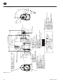
ST700 惯性装置尺寸
(IR No. SMB-441
Kit ST700-K166
441.98
(17.40”)
425.98
(16.77”)
69.80
(2.75”)
158.28
(6.23”)
117.00
(4.61”)
86.00
(3.39”)
175.00
(6.89”)
“2”
“3”
“1”
Ø 193.00
“0”
Ø 134.00
(5.28”)
ST700-166
35.70
(1.41”)
130.30
(5.13”)
317.50
(12.50”)
117.20
(6.98”)
85.85
(3.38”)
R71.00
(2.80”)
85.73
(3.38”)
22.35
(.88”)
Ø 152.00
(5.98”)
46.00
(1.81”)
50.80
(2.00”)
Ø 92.01
(3.62”)
114.20
(4.50”)
9.65
(.38”)
12.70
(.50”)
1/2”-13 UNC
19.1 (.75) - 4
Ø 1.50” J518C
4.8
4
4”
4” NPT
** 4” NTP
(IR No. SMB-441)
**
(IR No. SMB-441)
1. 1/4”
2.
3.
4.
IR No. SMB-441
Ø 137.50
(5.41”)
Ø 16.7
(.66”)
3-Places
7° 30’
120°
R 73.15
(2.88”)
H
J
I
K
L
M
N
O
P
A
B
C
D
E
F
G
- -
ST7 50 G B D I 03 R 31 - 0 N
4 @ 90° 16 @ 22 1/2°
1.
2.
3.
4. 6/5/89
5.
6. = 68 30.8
:
(图. TPA1276-4)
ZH

03537651_ed15 15
安装尺寸
ST7 50 G B D P 03 R 31 - 0 G
H
**
(IR No. SMB-441)
472.28
(18.59”)
363.80
(14.32”)
69.80
(2.75”)
35.70
(1.41”)
223.50
(8.80”)
138.50
(5.45”)
10.00
(.39”)
23.00
(.91”)
R76.00
(2.99”)
R71.00
(2.80”)
85.73
(3.38”)
50.80
(2.00”)
58.34
(2.30”)
160.50
(6.32”)
18.50
(.73”)
28.50
(1.13”)
7° 30’
91.98
(3.62”)
Pilot Dia.
R 73.00
(2.87”)
Ø 137.50
(5.41”)
“3”
“1”
“2”
488.28
(19.22”)
H
H
1/2”-13 UNC
.75” - 4
Ø 1.50” J518C
“0” “3”
#0
158.28
(6.23”)
117.00
(4.61”)
175.00
(6.89”)
“2”
“1”
“0”
“3”
86.00
(3.39”)
Ø 134.00
(5.28”)
ST700-166
**
1/4” NPT
= 70 150 P.S.I.G
(483 to 1034 kPa)
1/4” NPT
= 70 150 P.S.I.G
(483 to 1034 kPa)
1/8” NPT
H
H
H
“A” “P”
“G”
120°
Ø (.65”)16.60
3
SAE 3
16
16
“H”
“J”
“I”
“K”
“L”
“M”
“N”
“O”
“P”
“A”
“B”
“C”
“D”
“E”
“F”
“G”
(IR No. SMB-441
Kit ST700-K166
4.8
4
- -
4 @ 90°
16 @ 22 1/2°
1.
2. “OG”
“OG”
3. = 69 31.3
4.
5. Ingersoll Rand
6.
:
4” NPT
** 4” NTP
(IR No. SMB-441)
1/4”
1/4”
IR No. SMB-441
(图. TPA1277-5)
ZH

16 03537651_ed15
ST700 预先安装的安装尺寸
4” NPT
ST7 50 G D D P 09 R 51 - 0 E
4 @ 90° 16 @ 22 1/2°
158.28
(6.23”)
ST700-166
“2”
“3”
“1”
175.00
(6.89”)
“0”
117.00
(4.61”)
86.00
(3.39”)
Ø 134.00
(5.28”)
69.80
(2.75”)
35.70
(1.41”)
Ø 196.0
(7.72”)
1/8” NPT
Ø 152.35
(6.00”)
1/4 - 18 NPT
1/4 - 18 NPT
R 89.00
(3.50”)
99.00
(3.50”)
20.00
(.79”)
81.00
(3.19”)
102.00
(4.02”)
195.00
(7.70”)
186.50
(7.34”)
180.00
(7.09”)
168.00
(6.61”)
33.00
(1.30”)
20.00
(.79”)
306.29
(12.06”)
414.78
(16.33”)
5/16”- UNC
(.75) - 4
430.78
(16.96”)
41.50
(1.63”)
Ø 180.00
(7.09”)
Ø 228.60
(9.00”)
45°
90°
H
J
I
K
L
M
N
O
P
A
B
C
D
E
F
G
(IR No. SMB-441
Kit ST700-K166
4.8
4
1.
1/4”
2.
3.
4.
IR No. SMB-441
** 4” NTP
(IR No. SMB-441)
**
(IR No. SMB-441)
Ø 1.50”
J518C
1.
2.
3.
4. (OE)
5.
6. = 98 44.5
:
(图. TPA1278-4)
ZH

03537651_ed15 17
管道布置图
预啮合安装的系统(显示 ST700 系列)
1/4” NPT
ST700 - K166
ST700 - K166
1½”
SRV150
1½”
SRV150
1/2” N.P.T.
150BMP - 1067
150BMP - 1056
JIC 37° 1/4” N.P.T.
SS350 - MC4
JIC 37°
1½” N.P.T.
150BMP - 1064L
- 12
150BMP - 1051B
SMB-618 ( )
SMBG-618 ( )
**
1/8” N.P.T.
(2)
SMB - 618 ( )
#4 (1/4”)
#4 (1/4”)
#4 (1/4”)
#4 (1/4”)
1½”
*
150BMP - 1064L ( )
15 P.S.I.
Ingersoll Rand
1/4” N.T.P.
JIC 37° 1/4” N.P.T.
SS350 - MC4
1 ½” N.P.T.
1½”
**
1/8” N.P.T.
#4 Hose (1/4”)
1½”
SMB - 441
SMB - 441
* *
(图. TPA1282-3)
ZH

18 03537651_ed15
管道布置图
惯性啮合系统(显示 ST700 系列)
(2)
- 12
150BMP - 1051B
SMB - 618 ( )
#4 (1/4”)
150BMP - 1064L
JIC 37° 1/4” N.P.T.
SS350 - MC4
150BMP - 1056
1/2” N.P.T.
150BMP - 1067
1/4” NPT
SMB - 441
ST700 - K166
1 ½” N.P.T.
1½”
SRV150
1½”
1½”
JIC 37°
1½” N.P.T.
#4 (1/4”)
150BMP - 1064L ( )
#4 (1/4”)
JIC 37° 1/4” N.P.T.
SS350 - MC4
#4 (1/4”)
SMB-618 ( )
SMBG-618 ( )
ST700 - K166
1½”
1½”
SRV150
1/4” N.T.P.
*
* *
Ingersoll Rand
SMB - 441
15 P.S.I.
(图. TPA1283-3)
ZH

03537651_ed15 19
管道布置图
预啮合安装的系统(显示 ST700 系列)
1½”
SRV150
JIC 37° 1/4” N.P.T.
SS350 - MC4
JIC 37°
1½” N.P.T.
JIC 37°
1½” N.P.T.
#4
#4 (1/4”)
#4 (1/4”)
#4 (1/4”)
#4 (1/4”)
#4 (1/4”)
1 ½”
1 ½” N.P.T.
1½”
#4
1½”
1½”
150BMP - 1064L
( )
JIC 37° 1/4” N.P.T.
SS350 - MC4
JIC 37° 1/4” N.P.T.
SS350 - MC4
SMB - 618 ( )
#4 (1/4”)
1½”
SMB-618 ( )
SMBG-618 ( )
1½”
SRV150
*
*
ST700 - K166
15 P.S.I.
**
1/8” N.P.T.
SMB - 441
SMB - 441
1/4” N.T.P.
1/4” N.T.P.
* *
150BMP - 1064L ( )
**
1/8” N.P.T.
ST700 - K166
150BMP - 1056
* *
1/2” N.P.T.
150BMP - 1067
Ingersoll Rand
(图. TPA1281-3)
ZH

20 03537651_ed15
管道布置图
典型多起动器装置
ST700 - K166
JIC 37°
1½” N.P.T.
JIC 37°
1½” N.P.T.
JIC 37°
1½” N.P.T.
#4 (1/4”)
#4 (1/4”)
#4 (1/4”)
#4 (1/4”)
1½”
JIC 37° 1/4” N.P.T.
SS350 - MC4
JIC 37° 1/4” N.P.T.
SS350 - MC4
JIC 37° 1/4” N.P.T.
SS350 - MC4
JIC 37° 1/4” N.P.T.
SS350 - MC4
JIC 37° 1/4” N.P.T.
SS350 - MC4
JIC 37° 1/4” N.P.T.
SS350 - MC4
1½”
1½”
2 2-1/2”
3-1/2”
3-1/2”
3-1/2”
3”
4
4
3
3
4
5
ST750
150 PSIG
ST700
ST799
90 PSIG
#4 (1/4”)
#4 (1/4”)
1½”
1½”
SMB-618 ( )
SMBG-618 ( )
1½”
SRV150
1½”
SRV150
1½”
SRV150
**
1/8” N.P.T.
*
*
*
1/4” N.T.P.
Ingersoll Rand
**
1/8” N.P.T.
**
1/8” N.P.T.
SMB - 441
1/4” N.T.P.
1/4” N.T.P.
* *
(图. TPA1284-4)
ZH
ページが読み込まれています...
ページが読み込まれています...
ページが読み込まれています...
ページが読み込まれています...
ページが読み込まれています...
ページが読み込まれています...
ページが読み込まれています...
ページが読み込まれています...
ページが読み込まれています...
ページが読み込まれています...
ページが読み込まれています...
ページが読み込まれています...
ページが読み込まれています...
ページが読み込まれています...
ページが読み込まれています...
ページが読み込まれています...
ページが読み込まれています...
ページが読み込まれています...
ページが読み込まれています...
ページが読み込まれています...
ページが読み込まれています...
ページが読み込まれています...
ページが読み込まれています...
ページが読み込まれています...
ページが読み込まれています...
ページが読み込まれています...
ページが読み込まれています...
ページが読み込まれています...
ページが読み込まれています...
ページが読み込まれています...
ページが読み込まれています...
ページが読み込まれています...
-
 1
1
-
 2
2
-
 3
3
-
 4
4
-
 5
5
-
 6
6
-
 7
7
-
 8
8
-
 9
9
-
 10
10
-
 11
11
-
 12
12
-
 13
13
-
 14
14
-
 15
15
-
 16
16
-
 17
17
-
 18
18
-
 19
19
-
 20
20
-
 21
21
-
 22
22
-
 23
23
-
 24
24
-
 25
25
-
 26
26
-
 27
27
-
 28
28
-
 29
29
-
 30
30
-
 31
31
-
 32
32
-
 33
33
-
 34
34
-
 35
35
-
 36
36
-
 37
37
-
 38
38
-
 39
39
-
 40
40
-
 41
41
-
 42
42
-
 43
43
-
 44
44
-
 45
45
-
 46
46
-
 47
47
-
 48
48
-
 49
49
-
 50
50
-
 51
51
-
 52
52


Ingersoll-Rand ST750GBDI03R31 Installation And Maintenance Information
- タイプ
- Installation And Maintenance Information
他の言語で
- English: Ingersoll-Rand ST750GBDI03R31
関連論文
その他のドキュメント
-
Samsung SM-R350 取扱説明書
-
-
-
-
Philips HD2132/03 Product Datasheet
-
-
Enerpac VE42QM-115 Repair Service Instructions
-
Sanyo VA-80AC ユーザーマニュアル
-
Hitachi RAS-DX18HNK インストールガイド
-
Wacker Neuson VP60X Parts Manual