Ingersoll-Rand MULTI-VANE 92RB045 Operation And Maintenance Information
- タイプ
- Operation And Maintenance Information

Form P6401
Edition 7
January 2008
CCN: 03528635
Save These Instructions
Nonreversible and Reversible
MULTI-VANE® Geared Motors
Series 92N and 92R
Operation and Maintenance
Information
Operation and Maintenance Information
EN
操作和维护信息
ZH

2 03528635_ed7
EN
WARNING
General Product Safety Information
Read and understand this manual before operating this product.
It is your responsibility to make this safety information available to others that will operate this product.
Failure to observe the following warnings could result in injury.
WARNING
Always operate, inspect and maintain this motor in accordance with American National Standards Institute Safety Code for
Portable Air Tools (ANSI B186.1).
For safety, top performance and maximum durability of parts, operate this motor at 90 psig (6.2 bar/620 kPa) air pressure at the inlet with
1 1/4” (32 mm) air supply hose.
Always turn o the air supply and disconnect the air supply hose before installing, removing or adjusting any accessory on this motor or
before performing any maintenance on this motor.
Keep hands, loose clothing and long hair away from rotating end of motor.
Anticipate and be alert for sudden changes in motion during start up and operation of any motor.
Motor shaft may continue to rotate briey after throttle is released.
Do not lubricate motor with ammable or volatile liquids such as kerosene, diesel or jet fuel.
Do not remove any labels. Replace any damaged label.
Use accessories recommended by Ingersoll Rand.
This motor is not designed for working in explosive atmospheres.
This motor is not insulated against electric shock.
When installing one of these Motors for operation on compressed air, refer to the schematic diagram Drawing TPB-491.
NOTICE
The use of other than genuine Ingersoll Rand replacement parts may result in safety hazards, decreased tool performance and increased
maintenance, and may invalidate all warranties.
Ingersoll Rand is not responsible for customer modication of tools for applications on which Ingersoll Rand was not consulted.
Repairs should be made only by authorized, trained personnel. Consult your nearest Ingersoll Rand Authorized Servicenter.
It is the responsibility of the employer to place the information in this manual into the hands of the operator.
Safety Symbol Identication
Wear Respiratory
Protection
Wear Eye
Protection
Wear Hearing
Protection
Read Manuals Before
Operating Product
(Dwg. MHP2598)
Safety Information - Explanation of Safety Signal Words
DANGER
Indicates an imminently hazardous situation which, if not avoided, will result in death or serious injury.
WARNING
Indicates a potentially hazardous situation which, if not avoided, could result in death or serious injury.
CAUTION
Indicates a potentially hazardous situation which, if not avoided, may result in minor or moderate injury or
property damage.
NOTICE
Indicates information or a company policy that relates directly or indirectly to the safety of personnel or
protection of property.
■
■
■
•
•
•
•
•
•
•
•
•
•
•
•
•
•
•
•

03528635_ed7 3
EN
Lubrication
Always use an air line lubricator with these motors. We recommend
the following Filter-Regulator-Lubricator Unit: No. C31-08-600.
Install the Unit as close to the Motor as practical. Keep the
Lubricator lled with Ingersoll Rand No. 50 Oil.
NOTICE
If a sight feed lubricator is used, adjust the lubricator to feed 60
drops per minute for continuous duty operation. Whenever the
power unit is disassembled, work some Ingersoll Rand No. 28
Grease into the Rear Rotor Bearing (5).
Use a good quality SAE 90 Gear Lubricant in the gear box. The
amount of lubricant required is dependent upon the size of gear box
and the mounting position of the Motor.
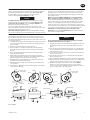
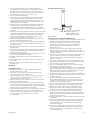
When lubricating the gear box, refer to Drawing TPB490 showing
the various mounting positions and the ll plugs, vent plug and drain
plug. In each case, ll the gear chamber up to the “Level” plug. If the
Vent Plug (40) is not located at the position indicated for a given
mounting, relocate the Vent Plug by interchanging it with the pipe
plug at that location.
Whenever a Series 92NB or 92RB Motor is mounted with the
Motor Shaft (36) pointing toward the oor or ceiling, you must
install a gravity feed lubrication to make certain the gears in the
upper portion of the gear box get adequate lubrication. To do this,
remove one of the pipe plugs other than the Vent plug from the
upper side of the motor and connect an oil line from a gravity feed
reservoir. Connect an overow line to the Level Plug opening and run
it to a pump to return the lubricant to the gravity feed reservoir.
If the Motor is mounted in any position other than that
illustrated, contact an Ingersoll Rand Representative for oil level
and venting recommendations.
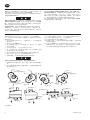
Direction of Shaft Rotation
Series 92N Non-reversible Motors are assembled at the factory so
that the Motor Shaft (36) rotates counterclockwise when facing the
end of the Shaft. When desired, the direction of the shaft rotation can
be changed as follows:
1. Stand the Motor upright on a workbench with the Motor Housing
Cover (1) upward and secure it in position by clamping the base
with a C-clamp.
2. Remove the four Housing Cover Cap Screws (2).
3. Being careful not to damage the Cylinder Seals (8A), pull the
Motor Housing Cover and the Motor Housing (11) o the Gear
Box (18).
4. Grasp the Cylinder (8) with both hands and carefully work the
motor from the Gear Box.
5. While holding the Cylinder with one hand, drive against the
splined end of the Rotor (12) with a soft hammer until the Front
Rotor Bearing (13) comes free from the rotor shaft.
6. Withdraw the Front Rotor Bearing, Front Rotor Bearing Spacer
Assembly (14) and Front End Plate (7).
7. Withdraw the Cylinder (8), turn it end-for-end, and slide it back
over the Rotor.
8. Install the Front End Plate, Front Rotor Bearing Spacer Assembly
and Front Rotor Bearing.
NOTICE
Press against the inner ring of the Bearing when pressing the
Front Rotor Bearing on the rotor shaft.
9. Align the dowel hole in both End Plates and Cylinder, and insert
the Cylinder Dowel (9) so that it protrudes from the Rear End
Plate.
10. Place the Housing Cover Gasket (4) in the recess in the Housing
Cover so that the dowel notch in the Gasket is aligned with the
dowel hole in the Cover.
11. Set the motor assembly in the Cover so that the Cylinder Dowel
enters the dowel hole.
12. Slide the Motor Housing (11) over the Cylinder and against the
Motor Housing Cover.
13. Place the Gear Box Gasket (17) on the face of the Front End Plate.
14. Pick up the entire assembly and being careful not to damage the
Cylinder Seals, work it into the pilot recess in the gear box.
15. Install the Housing Cover Cap Screws and, with the MotorMotor
running at a slow speed using air pressure of 30 to 40 psig
(2.07 to 2.76 bar/207 to 276 kPa), alternately tighten the Screws
to 28 to 31 ft-lb. (38.0 to 42.0 Nm) torque.
Fill
Fill
Vent (In gear
box cover)
Fill
Vent (In gear
box cover)
Vent
Fill and
Vent
Fill and Vent
Fill and Vent
Fill and Vent
Fill and
Vent
Level
Level
Level
Level
Level
Level
Level
Level
Drain
Drain
Drain
Drain
Drain
Drain
Drain
Drain
Floor
Floor
Floor
Floor
Floor
Floor
Floor
Floor
(Dwg. TPB490)

4 03528635_ed7
EN
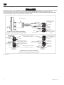
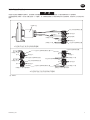
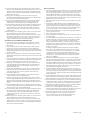
Reversible Motor Applications Air Flow Information
NOTICE
When these motors are used on applications requiring a reversible motor, a 4-way throttle valve or two 3-way throttle valves must be
used in the air supply line in accordance with the following schematic diagram (TPB491). When the application requires a
non-reversible motor, a 2-way inline valve can be used in the air supply line. In either case, the inlet and outlet of the valve must be
equal in size, and preferably one size larger, than the inlet of the motor.
Valve positioned for
forward operation
of motor
Valve positioned for
forward operation
of motor
Valve positioned for
reverse operation
of motor
Valve positioned for
reverse operation of motor
Valve positioned for
reverse operation of motor
Valve positioned for
forward operation of motor
Relative positions of valves for
forward operation of motor
Relative positions of valves for
reverse operation of motor
Two three-way valves for controlling
forward and reverse operation of motor
Three-way throttle valve
in air line to
forward inlet
Four-way
throttle
valve
Air line to
reverse inlet
Air line to
reverse inlet
Air line to
forward inlet
Air line to
forward inlet
Reverse Inlet
Forward Inlet
Reversible Motor
Single four-way valve for controlling
forward and reverse operation of motor
Air line to
forward inlet
Air line to
reverse inlet
Three-way throttle valve
in air line to
reverse inlet
Live Air
Live Air
Live Air
Live Air
Live Air
Exhaust
Exhaust
Live Air
Exhaust
Exhaust
Exhaust
Exhaust
(Dwg. TPB491)

03528635_ed7 5
ZH
通用产品安全信息
使用产品前请阅读并理解本手册。
您有责任为其他操作该产品的人员提供本安全手册。
不按照以下警告进行操作将可能导致人员受伤。
请始终按照美国国家标准协会移动式空气工具安全标准 (ANSI B186.1) 使用、检查和维护该马达。
为了工具的使用安全、最大性能、以及最长使用寿命。请确保马达的进气口压力为90psig(6.2巴/620kPa),并使用规格为1.25英寸(
32毫米)的进气软管。
请务必在安装、移动或更换马达部件、或进行任何维修之前关闭并切断气源。
保持手、宽松的衣服、长头发远离马达旋转端。
请留心和注意马达启动和旋转过程中出现的运转异常变化。
气阀松开后马达轴可能仍会短暂旋转。
请勿使用易燃易爆液体如煤油、柴油或喷气机燃料来润滑马达。
请勿撕掉任何标签。请更换任何受损的标签。
使用 Ingersoll Rand 推荐配件。
该马达的设计决定了其不适用于爆炸性气体。
该马达没有防电击的绝缘装置。
当在压缩空气下安装这些马达中的任何一种,请参考TPB-491示意图。
使用非 Ingersoll Rand 原装零部件将可能导致安全事故、工具性能降低、维护工作增加,并将丧失所有的质量保证。
用户若没有咨询 Ingersoll Rand 而擅自对工具应用进行改动,Ingersoll Rand 将不对其产生的后果负任何责任。
维修须由授权并经过培训的专业人员进行。 咨询您最近的 Ingersoll Rand 授权维修中心。
卖家有责任将本手册交到用户手中。
安全标识识别。
戴呼吸保护
装置
戴防护
眼镜
戴听力保护
装置
在操作产品前请阅
读手册
(图: MHP2598)
安全信息: 安全信号文字解释
即将发生的危险情况,若不避免,则将导致严重的伤害或死亡。
潜在的危险情况,若不避免,则将导致严重的伤害或死亡。
潜在的危险情况,若不避免,则将导致轻微或中度的伤害或财产损失 。
与人身安全或财产安全直接或间接有关联的信息及公司政策。
■
■
■
•
•
•
•
•
•
•
•
•
•
•
•
•
•
•
•

6 03528635_ed7
ZH
润滑
请使用空气管路润滑器对马达进行润滑。 我们推荐下面过滤、调
压和润滑为一体的三联件: 编号为: C31-08-600
请尽可能将三联件安装在靠近马达的地方。确保润滑器内使用的
是Ingersoll Rand 50#油。
若使用可视润滑器,为了连续使用,将润滑器设置到每分钟60滴。
无论什么时候拆下动力部件,在转子后轴承 (5) 中加入 28 号润滑
脂。 在齿轮箱中使用优质的 SAE90 齿轮润滑剂。 润滑剂的用量
取决于齿轮箱的尺寸和马达的安装位置。
当润滑齿轮箱时,请参照 TPB490 图纸, 该图纸上显示各种安装
位置和进口、出口及排污口. 不管在什么情况下,请添加至“液
位”插口位置。 若出口塞 (40) 不在指定的安装位置上,将其与在
该位置上的管塞调换位置。
无论什么时候安装 92NB 或 92RB 系列马达,并且马达轴(36)
指向地或者天花板时,为确保齿轮箱上部得到良好润滑,必须安
装一个重力式润滑系统。 为此,拆下一个管塞,而不是从马达上
端拆下孔塞,并且从重力式加油箱连接一根油管。 从水平塞开口
引一根溢流管到油泵,以使润滑油返回到重力加油箱。
若马达安装在图示位置以外的其它位置,请联系 Ingersoll Rand
代表咨询油位和出口推荐位置。
轴转动方向
92N 系列不可逆转马达在出厂时已经安装好,所以从轴端来看
时,马达轴(36)逆时针旋转。 若需要,可以按照以下方法改变
轴的转动方向:
1. 把马达垂直摆放在工作台上,马达罩 (1) 向上,用卡钳夹紧底
部以定位。
2. 拆下四个马达罩帽螺钉 (2) 。
3. 将马达罩和马达盖(11)从齿轮箱(18)拿出来,小心不要损
坏气缸密封圈 。
4. 双手抓住气缸 (8),小心从齿轮箱上拆下马达。
5. 用一只手抓住气缸,用软锤子敲打转子(12)的花键端,直到
转子前轴承 (13) 从转轴上脱开。
6. 取下转子前轴承、转子前轴承垫圈组件 (14) 和前端板 (7)。
7. 取出气缸 (8),调换一头,然后再套回到转子上。
8. 安装前端板,转子前轴承垫圈组件和转子前轴承。
当将转子前轴承压在转子轴上时,请压在轴承的内环上。
9. 将端板和气缸的销孔对齐,插入气缸销,销子会从后端板露出
来。
10. 把马达罩垫圈 (4) 放回到马达罩凹槽中,以使垫圈的键槽口和
盖子的销孔对齐。
11. 在马达罩中放置好马达组件,以便气缸销子准确落入销孔中。
12. 从气缸上滑动马达盖(11),与马达罩对好。
13. 将齿轮箱垫圈 (17) 放在前端板上面。
14. 拿起整个组件,小心把它装到齿轮箱的导向槽中,注意不要将
气缸密封垫损坏。
15. 安装马达罩帽螺钉时,使用30到40psig(2.07到2.76巴/207到
276kPa)的气压,将马达保持在一个低速运转的状态,交替地
将各个螺钉拧紧到扭矩为28到31英尺磅(38到42牛米)。
(图: TPB490)

03528635_ed7 7
ZH
可反转马达应用气流信息
当这些马达在应用被要求可反转时,必须按照下面示意图 (TPB491) 所示在气路上使用一个4通节流阀或两个 3 通节流阀。
当马达需要不可反转时,可以在气路上使用一个 2 通阀。 以下两种情况均可行: 阀出口和进口尺寸必须相等,或出口尺寸大于进口尺寸
更好。
1
2
(图: TPB491)

8 03528635_ed7
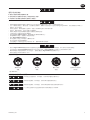
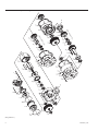
92N and 92R Series Exploded Diagram
8A
8A
7
4
5
6
1
3
2
11
10
12
42
41
38
40
20
39
35
37
36
26
34
20
19
30
29
26
27
28
32
33
36
37
35
39
30
20
38
40
42
41
18
43
24
23
21
22
13
14
16
15
17
7
31
Series 92NA or 92
RA
Series 92NB or 92RB
25
9
8
(Dwg. TPA551-1)

03528635_ed7 9
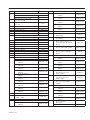
92N and 92R Series Parts List
Item Description Part Number Item Description Part Number
1 Motor Housing Cover for Model 92NA008 or
48NA-755-008
for Series 92N 92N-102 92RA008
for Series 92R 92R-102 for Model 92NA011 or
48NA-755-011
2 Short Housing Cover Cap Screw
12BMP-634
92NA011
(4 for 92N; 2 for 92R) for Model 92NA014 or
48NA-755-014
•
Long Housing Cover Cap Screw
(2 for 92R)
107-25
92RA014
for Model 92NA017 or
48NA-755-017
3 Copper Seal Washer (4) D02-504 92RA017
• 4 Motor Housing Cover Gasket 92R-283
for Model 92NA022 or
92RA022
48NA-755-022
• 5 Rear Rotor Bearing 92RMG10-22
6 Rear Rotor Bearing Retainer R380Q-6 for Series 92NB or 92RB
7 End Plate (2) 92RMG10-11 • 22
First Stage Intermediate Gear
Rear Bearing
R1AP-97
8 Cylinder Assembly
for Series 92N 92RMG10-A3 • 23
First Stage Intermediate Gear
Front Bearing
R38P-97
for Series 92R 92R-A3
8A Cylinder Seal (2) 92RMG10-103 • 24
Motor Shaft Rear Bearing or
Intermediate Gear Pinion Rear
Bearing
48NA-510
9 Cylinder Dowel 92R-98
• 10 Vane Packet (set of 5 Vanes) R5H-42-5
11 Motor Housing 92N-40 • 25
Second Stage Intermediate
Gear (for Series 92NB or 92RB)
48NA-756-022
12 Rotor 92N-53
• 13 Front Rotor Bearing T02-33 • 26
Second Stage Intermediate
Gear Key or Motor Shaft Gear
Key (2)
R4H-41014 Front Rotor Bearing Spacer Assembly 92N-A65
• 15 Front Rotor Seal 48N-758
• 16 Bearing Spacer Seal AF160-294 27 Intermediate Gear Pinion
• 17 Gear Case Gasket 92R-283
for Model 92NB029 or
92RB029
48NB-760-029
Gear Box Assembly
for Model 92NA005 or
92RA005
92NA-A750-005
for Model 92NB036 or
92RB036
48NB-760-036
for Model 92NA008 or
92RA008
92NA-A750-008
for Model 92NB045 or
92RB045
48NB-760-078
for Model 92NA011 or
92RA011
92NA-A750-011
for Model 92NB078 or
92RB078
48NB-760-078
for Model 92NA014 or
92RA014
92NA-A750-014
• 28 Intermediate Gear Pinion
Roller Bearing (for Series
92NB or 92RB)
48NB-765
for Model 92NA017 or
92RA017
92NA-A750-017
• 29
Intermediate Gear Pinion
Front Bearing (for Series
92NB or 92RB)
48NB-764
for Model 92NA022 or
92RA022
92NA-A750-022
for Model 92NB029 or
92RA029
92NB-A750-029
• 30 Third Stage Intermediate Gear
Bearing (for Series 92NB or
92RB) (2)
C6H20A-518
for Model 92NB036 or
92RA036
92NB-A750-036
31 Third Stage Intermediate Gear
for Model 92NB045 or
92RA045
92NB-A750-045
for Model 92NB029 or
92RB029
48NB-761-029
for Model 92NB078 or
92RA078
92NB-A750-078
for Model 92NB036 or
92RB036
48NB-761-036
18 Gear Box 92NA-750 for Model 92NB045 or
48NB-761-045
19
Gear Box Frame (for Series
92NB or 92RB)
48NB-763
92RB045
for Model 92NB078 or
48NB-761-078
• 20 Gear Box Gasket 48NA-752 92RB078
21 First Stage Intermediate Gear • 32
Motor Shaft Thrust
Bearing Race
for Model 92NA005 or
92RA005
48NA-755-005
for Series 92NB or 92RB 48NB-767

10 03528635_ed7
Item Description Part Number Item Description Part Number
• 33 Motor Shaft Thrust Bearing 37 Motor Shaft Key
for Series 92NB or 92RB 48NB-769 for Series 92NA or 92RA 107-54
34 Motor Shaft Gear for Series 92NB or 92RB R5H51-768
for Model 92NA005 or 92RA005 48NA-756-005 38 Gear Box Cover Assembly
for Model 92NA008 or 92RA008 48NA-756-008 for Series 92NA or 92RA 48NA-A751
for Model 92NA011 or 92RA011 48NA-756-011 for Series 92NB or 92RB 48NB-A751
for Model 92NA014 or 92RA014 48NA-756-014 • 39 Motor Shaft Seal
for Model 92NA017 or 92RA017 48NA-756-017 for Series 92NA or 92RA 48NA-759
for Model 92NA022 or 92RA022 48NA-756-022 for Series 92NB or 92RB 48NB-759
• 35 Motor Shaft Front Bearing 40 Vent Plug 48NA-368
for Series 92NA or 92RA C6H20A-518 41 Gear Box Cover Cap Screw (11)
for Series 92NB or 92RB 48NB-766 for Series 92NA or 92RA R0H-354-4
36 Motor Shaft for Series 92NB or 92RB 48NB-354
for Series 92NA or 92RA 48NA-757-4 42 1/4 Lock Washer (11) 8U-58
for Model 92NB029, 92RB029
92NB036, 92RB036,
92NB045 or 92RB045
48NB-762-029
43
Oil Plug (12 for Series 92NB or
92RB; 11 for others)
R2-227
* Nameplate 92N-301
for Model 92NB078 or 92RB078 48NB-762-078 * Nameplate Screw (3) 20BM-302
* Not illustrated
• To keep downtime to a minimum, it is desirable to have on hand certain repair parts. We recommend that you stock one (pair or set) of each
part indicated by a bullet (•) for every four motors in service.
92N and 92R Series Parts List (Continued)
Maintenance Section
Disassembly
General Instructions
1. Do not disassemble the motor any further than necessary to
replace or repair damaged parts.
2. Do not disassemble the motor unless you have a complete set of
new gaskets and O-rings for replacement.
3. When grasping a motor or part in a vise, always use leather-
covered or copper-covered vise jaws to protect the surface of the
part or motor and help prevent distortion. This is particularly true
of threaded members and housings.
4. Do not remove any part which is a press t in or on a
sub-assembly unless the removal of that part is necessary for
repairs or replacement.
5. Do not press any needle bearing from a part unless you have a
new needle bearing on hand for installation. Needle bearings are
always damaged during the removal process.
Disassembly of the Motor
1. Remove the Vent Plug (40) and positioning the Drain Plug (43)
over a container, remove the Drain Plug and drain the lubricant
from the Gear Box (18). Clamp the mounting foot of the Gear Box
to the work bench.
2. Remove the Housing Cover Cap Screws (2) and Washers (3).
3. Grasp the Motor Housing (11) and Motor Housing Cover (1) and
separate the motor parts from the Gear Box.
4. Separate the Motor Housing Cover from the Motor Housing and
being careful not to damage the Cylinder Seals (8A), grasp the
spline end of the Rotor (12) and pull the assembled motor out of
the Motor Housing.
5. Pull the Front Rotor Bearing (13), Front Rotor Bearing Spacer
Assembly (14) and Front End Plate (7) o the hub of the Rotor.
6. Peel the Gear Case Gasket (17) from the End Plate. If portions of
the Gasket remain adhered to the End Plate, use a scrapper made
from a non-damaging material such as nylon, to scrap the Gasket
and adhesive from the End Plate.
7. Pull the Cylinder (8) and Cylinder Dowel (9) o the Rotor and
remove the Vanes (10) from the vane slots in the Rotor.
8. Remove the two Cylinder Seals (8A) from the grooves in the large
anges of the Cylinder.
9. Using snap ring pliers, remove the Rear Rotor Bearing Retainer (6)
and pull the Rear Rotor Bearing (5) and End Plate o the rear hub
of the Rotor.
10. Peel the Motor Housing Cover Gasket (7) from the End Plate. If
portions of the Gasket remain adhered to the End Plate, use a
scrapper made from a non-damaging material such as nylon, to
scrap the Gasket and adhesive from the End Plate.
Disassembly of Series 92NA and 92RA Gearing
1. Unscrew and remove the eleven Gear Box Cover Cap Screws (41)
and Lock Washers (42).
2. Remove the Motor Shaft Key (37) and lay the assembled gear box
on a workbench with the Motor Shaft (36) upward.
3. Carefully separate the Gear Box Cover Assembly (38) from the
Gear Box (18) and set it aside. If the Intermediate Gear (21)
remains with the Gear Box Cover, make certain it does not drop
onto any hard surfaces or other gearing.
4. Remove the Gear Box Gasket (20).
5. Lift the Intermediate Gear out of the Gear Box. Pull the First Stage
Intermediate Gear Rear Bearing (22) and First Stage Intermediate
Gear Front Bearing (23) o the hubs of the Intermediate Gear.
If the Bearings are frozen on the hubs, use a bearing puller to
remove them.
6. Push the assembled Motor Shaft out of the Gear Box Cover
Assembly.
7. Pull the Motor Shaft Rear Bearing (24) o the rear hub of the
Motor Shaft.
8. Pull the Motor Shaft Front Bearing (35) o the front hub of the
Motor Shaft.
9. Using a gear puller, pull the Motor Shaft Gear (34) o the rear of
the Motor Shaft. Remove the two Shaft Keys (26).
10. Using a hooked tool, pull the Motor Shaft Seal (39) out of the
Gear Box Cover.
Disassembly of Series 92NB and 92RB Gearing
1. Unscrew and remove the eleven Gear Box Cover Cap Screws (41)
and Lock Washers (42).
2. Remove the Motor Shaft Key (37) and lay the assembled gear box
on a workbench with the Motor Shaft (36) upward.

03528635_ed7 11
3. Grasp the Gear Box Frame (19) and carefully separate the
assembled Frame and Gear Box Cover Assembly (38) from the
Gear Box (18) and set it aside. If the First Stage Intermediate
Gear (21) remains with the Gear Box Frame, make certain it does
not drop onto any hard surfaces or other gearing.
4. Remove the Gear Box Gasket (20).
5. Lift the First Stage Intermediate Gear out of the Gear Box. Pull
the First Stage Intermediate Gear Rear Bearing (22) and First
Stage Intermediate Gear Front Bearing (23) o the hubs of the
Intermediate Gear. If the Bearings are frozen on the hubs, use a
bearing puller to remove them.
6. Carefully separate the Gear Box Cover Assembly from the Gear
Box Frame and remove the Gear Case Gasket. Be careful not
to allow the Motor Shaft Thrust Bearing Race (32) or the Motor
Shaft Thrust Bearing (33) to slide o the Motor Shaft and become
damaged.
7. Remove the Third Stage Intermediate Gear (31) and the two Third
Stage Intermediate Gear Bearings (30) from either the Gear Box
Frame or the Gear Box Cover Assembly. Pull the two Bearings
from the shafts of the Gear. If the Bearings are frozen on the
shafts, use a bearing puller to remove them.
8. Pull the Intermediate Gear Pinion Rear Bearing (24) o the rear
hub of the Intermediate Gear Pinion (27).
9. Using a gear puller, pull the Second Stage Intermediate Gear (25)
from the rear hub of the Intermediate Gear Pinion. Remove the
two Shaft Keys (26).
10. Push the Intermediate Gear Pinion out the motor shaft end of the
Gear Box Frame.
11. Pull the Intermediate Gear Pinion Front Bearing (29) o the Pinion
and if the Intermediate Gear Pinion Roller Bearing (28) must be
replaced, pull it from the Pinion.
12. If the Motor Shaft Thrust Bearing and Bearing Race have not been
removed, remove them from the Shaft.
13. Push the assembled Motor Shaft out of the Gear Box Cover
Assembly.
14. Pull the Motor Shaft Front Bearing (35) o the front hub of the
Motor Shaft.
15. Using a hooked tool, pull the Motor Shaft Seal (39) out of the
Gear Box Cover.
Assembly
General Instructions
1. Always press on the inner ring of a ball-type bearing when
installing the bearing on a shaft.
2. Always press on the outer ring of a ball-type bearing when
pressing the bearing into a bearing recess.
3. Whenever grasping a tool or part in a vise, always use leather-
covered or copper-covered vise jaws. Take extra care not to
damage threads or distort housings.
4. Except for bearings, clean every part and wipe every part with a
thin lm of oil before installation.
5. Check every bearing for roughness. If an open bearing must be
cleaned, wash it thoroughly clean suitable solution and dry with
a clean cloth. Sealed or shielded bearings should not be cleaned.
Work grease into every bearing before installation.
6. Apply a lm of O-ring lubricant to every O-ring before installation.
7. Unless otherwise noted, always press on the stamped end of a
needle bearing when installing a needle bearing into a recess.
Use a bearing inserting tool similar to the one shown
in Dwg. TPD786.
Needle Bearing Inserting Tool
Shoulder to
regulate depth
15°
Pilot to fit i.d. of bearing.
Length of pilot to be
approximately 1/8” less
than length of bearing.
(Dwg. TPD786)
Assembly of Series 92NB and 92RB Gearing
1. Using a bearing inserting tool, press the Intermediate Gear Pinion
Roller Bearing (28) into the Intermediate Gear Pinion (27).
2. Using a piece of tubing that contacts the outer ring of the
Intermediate Gear Pinion Bearing (29), press the Bearing
into the large bearing recess in the spindle side of the
Gear Box Frame (19).
3. Insert the shaft of the Intermediate Gear Pinion through the
Bearing and Frame, and rest the assembly on the table of an
arbor press with the pinion shaft upward and the gear end face of
the pinion supported.
4. Insert the two Second Stage Intermediate Gear Keys (26) into the
slots in the shaft and press the Second Stage Intermediate
Gear (25) onto the pinion shaft capturing the Gear Box Frame
within the assembly.
5. Using a piece of tubing that contacts the inner ring of the Third
Stage Intermediate Gear Bearing (30), press a Bearing onto each
shaft of the Third Stage Intermediate Gear (31).
6. Place the assembled Gear Box Frame on a workbench with the
roller bearing end of the Pinion upward.
7. Position the Bearing nearest the large spline on the shaft of Third
Stage Intermediate Gear above the bearing recess in the Gear Box
Frame. Engage the large spline of the Gear with the spline of the
Pinion while pushing the Bearing into the recess.
8. Using a piece of tubing that contacts the inner ring of the Motor
Shaft Front Bearing (35), press the Bearing onto the output end of
the Motor Shaft (36).
9. Install the Motor Shaft Thrust Bearing (33) followed by the
Motor Shaft Thrust Bearing Race (32) onto the opposite end of
the Motor Shaft and insert the assembled Shaft, Bearing Race
leading, into the Pinion Roller Bearing.
10. Place one of the Gear Box Gaskets (20) onto the Gear Box Frame
making certain the Gasket ts over the alignment pin in the
Frame and ts well around the large, raised alignment hub.
11. Using a dowel, push the Motor Shaft Seal (39), small opening
leading, into the recess in the Gear Box Cover Assembly (38).
12. Position the Cover over the Box Frame and install the Seal on
the Motor Shaft by bringing the Cover down against the Gasket.
Make certain the alignment pin and hub on the Frame enter the
hole and recess in the Cover.
13. Turn the assembly over so that the output end of the Motor Shaft
is downward.
14. Using a piece of tubing that contacts the inner ring of the First
Stage Intermediate Gear Front Bearing (23), press the Bearing
onto the shaft adjacent to the small spline of the First Stage
Intermediate Gear (21).
15. Using a piece of tubing that contacts the inner ring of the First
Stage Intermediate Gear Rear Bearing (22), press the Bearing
onto the shaft adjacent to the large spline of the First Stage
Intermediate Gear (21).

12 03528635_ed7
16. Position the Bearing nearest the smaller spline on the shaft of
the First Stage Intermediate Gear above the bearing recess in the
Gear Box Frame. Engage the smaller spline of the Gear with the
spline of the Second Stage Intermediate Gear while pushing the
Bearing into the recess.
17. Using a piece of tubing that contacts the inner ring of the
Intermediate Gear Pinion Rear Bearing (24), press a Bearing onto
the shaft of the Intermediate Gear Pinion.
18. Place the remaining Gear Box Gasket onto the Gear Box Frame
making certain the Gasket ts over the alignment pin in the
Frame and ts well around the large, raised alignment hub.
19. Position the Gear Box (18) over the assembly and bring the Gear
Box down against the Gasket while making sure the Bearings
enter the bearing recesses in the Gear Box. Make certain the
alignment pin and hub on the Frame enter the hole and recess
in the Gear Box.
20. While keeping the assembly together, turn it over and insert the
eleven Gear Box Cover Cap Screws (41) with their Lock
Washers (42) through the holes of the Cover and Frame and into
the Gear Box. Tighten the Screws evenly, a little at a time, using
an alternating pattern. Use the Screws to draw the assembly
together without distortion and without binding.
Assembly of Series 92NA and 92RA Gearing
1. Insert the two Motor Shaft Gear Keys (26) into the slots in the
Motor Shaft (36) and press the Motor Shaft Gear (34) onto the
Motor Shaft.
2. Using a dowel, push the Motor Shaft Seal (39), small opening
leading, into the recess in the Gear Box Cover Assembly (38).
3. Using a piece of tubing that contacts the inner ring of the Motor
Shaft Front Bearing (35), press the Bearing onto the output end of
the Motor Shaft.
4. Using a piece of tubing that contacts the inner ring of the Motor
Shaft Rear Bearing (24), press a Bearing onto the motor end of the
Motor Shaft.
5. Insert the output end of the Motor Shaft through the Motor Shaft
Seal and push it into the into the gear Box Cover Assembly until
the Motor Shaft Front Bearing seats in the bearing recess.
6. Using a piece of tubing that contacts the inner ring of the First
Stage Intermediate Gear Front Bearing (23), press the Bearing
onto the shaft adjacent to the small spline of the First Stage
Intermediate Gear (21).
7. Using a piece of tubing that contacts the inner ring of the First
Stage Intermediate Gear Rear Bearing (22), press the Bearing
onto the shaft adjacent to the large spline of the First Stage
Intermediate Gear (21).
8. Place the Gear Box Cover Assembly on a workbench with the
output end of the Motor Shaft downward.
9. Position the Bearing nearest the smaller spline on the shaft of
the First Stage Intermediate Gear above the bearing recess in the
Gear Box Cover. Engage the smaller spline of the Gear with the
spline of the Motor Shaft Gear while pushing the Bearing into the
recess.
10. Place the Gear Box Gasket (20) onto the Gear Box Cover making
certain the Gasket ts over the alignment pin in the Cover and ts
well around the large, raised alignment hub.
11. Position the Gear Box (18) over the assembly and bring the Gear
Box down against the Gasket while making sure the Bearings
enter the bearing recesses in the Gear Box. Make certain the
alignment pin and hub on the Frame enter the hole and recess
in the Gear Box.
12. While keeping the assembly together, turn it over and insert the
eleven Gear Box Cover Cap Screws (41) with their Lock
Washers (42) through the holes of the Cover into the Gear Box.
Tighten the Screws evenly, a little at a time, using an alternating
pattern. Use the Screws to draw the assembly together without
distortion and without binding.
Motor Assembly
1. The Gear Case Gasket (17) has adhesive on one side of the Gasket.
Place one End Plate (7) at on a clean surface with the face having
the channel going from the central opening to the outer edge
upward. Orient the Gasket to the End Plate, making certain the
cylinder dowel hole openings align, and attach it to the End Plate
by bringing the gasket adhesive into contact with the face of the
End Plate. Press it at onto the face.
2. Slip the End Plate, gasket face trailing, onto the spline end of the
Rotor (12).
3. Install the Front Rotor Bearing Spacer Assembly (14) and the
Front Rotor Bearing (13) onto the splined shaft of the Rotor and
against the End Plate. If the Bearing is a tight t on the shaft, use
a piece of tubing that contacts the inner ring of the Bearing and
clears the rotor shaft to press the Bearing onto the shaft.
4. While holding the Rotor in a vertical position, grasp the spline in
copper-covered vise jaws.
5. Place a Vane (10) in each vane slot.
6. Install new Cylinder Seals (8A) in the grooves in the large hubs of
the Cylinder (8).
7. For Series 92N Non-reversible Motors, the direction of rotation of
the Motor depends on the relationship of the Cylinder and End
Plates. To obtain desired shaft rotation, proceed as follows:
a. Rotate the End Plate until the 17/64” (6.75 mm) through hole
(dowel hole) is facing you. Note there is a similar hole extending
lengthwise through the Cylinder, and at about 40 to one side of
the hole is an air port.
b. Hold the Cylinder upright, facing the dowel hole and with
the air port to the right for clockwise shaft rotation, to the left
for counterclockwise shaft rotation. Then place it over the Rotor
so that the dowel hole in the Cylinder and End Plate are in
alignment. For Series 92R Reversible Motors, place the Cylinder
over the Rotor so that the dowel hole in the Cylinder and End
Plate are in alignment.
8. The Gear Case Gasket has adhesive on one side of the Gasket.
Place the remaining End Plate at on a clean surface with the face
having the channel going from the central opening to the outer
edge upward. Orient the Gasket to the End Plate, making certain
the cylinder dowel hole openings align, and attach it to the End
Plate by bringing the gasket adhesive into contact with the face
of the End Plate. Press it at onto the face.
9. Install the End Plate, Gasket side trailing, onto the short hub of
the Rotor. Rotate it so that the cylinder dowel hole is aligned with
the corresponding hole in the Cylinder. Insert the Cylinder Dowel
(9) to maintain the alignment with the Dowel protruding through
the Rear End Plate.
10. Slide the Rear Rotor Bearing (5) on the short hub of the Rotor and
against the End Plate. Using snap ring pliers, install the Rear Rotor
Bearing Retainer (6) to keep the Bearing and End Plate in position.
11. Position the Motor Housing Cover (1) over the Rear Rotor Bearing
and End Plate. Make certain the cylinder dowel holes and porting
are aligned correctly. Remove the assembly from the vise jaws.
12. Carefully slide the Motor Housing (11) over the assembled motor
and position it against the Motor Housing Cover.
13. Position the assembled Gear Box (18) against the face of the
Motor Housing. Make certain the spline of the Rotor engages the
teeth of the First Stage Intermediate Gear (21) properly.
14. Install the Housing Cover Cap Screws (2) along with the
Washers (4). With the motor running at a slow speed
(30 to 40 psig) (267 to 276 kPa) alternately tighten the
Screws to 28 to 31ft-lb. (38.0 to 42.0 Nm) torque.

Notes:

Notes:

Notes:

www.irtools.com
© 2008 Ingersoll Rand Company
-
 1
1
-
 2
2
-
 3
3
-
 4
4
-
 5
5
-
 6
6
-
 7
7
-
 8
8
-
 9
9
-
 10
10
-
 11
11
-
 12
12
-
 13
13
-
 14
14
-
 15
15
-
 16
16


Ingersoll-Rand MULTI-VANE 92RB045 Operation And Maintenance Information
- タイプ
- Operation And Maintenance Information
他の言語で
- English: Ingersoll-Rand MULTI-VANE 92RB045