
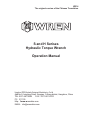
S and H Serises
Hydraulic Torque Wrench
Operation Manual
Hangzhou WREN Hydraulic Equipment Manufacturing Co.Ltd
Add:No 24 xingxing Road, Xingqiao, Yuhang district, Hangzhou, China
TEL: 0571-88110295 FAX:0571-88110210
PC311100
Http://www.wrenchina.com
W214
The original version of the Chinese Translation

Catalog
Important Receiving Instructions …………………………………1
S Series,Square Drive Torque Wrenches
H Series,LOW Profile Torque Wrenches
Waring And Caution
Operating The Wrench
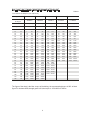
S Series Hydraulic Torque Wrench Pressure-Torque Chart
S Series Hydraulic Torque Wrench Pressure-Torque Chart
H Series Hydraulic Torque Wrench Pressure-Torque Chart
H Series Hydraulic Torque Wrench Pressure-Torque Chart
Inspect、Repair And Maintain
EC Declaration Of Conformity
Bolting Tightening Force Recommented Chart
…………………………………1
…………………………………2
…………………………………………2
…………………………4
…………………………………………5
…………9
…………10
…………11
…………12
………………………………………13
……………………………6 8
Operation
………………………………………18
………………………………………14 17
Specification & Parameter
Waring Plate
…………………………………………3
~
~

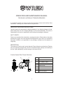
OPERATION AND MAINTENANCE MANUAL
FOR S AND H HYDRAULIC TORQUE WRENCHES
IMPORTANT RECEIVING INSTRUCTIONS
①
②
③
④
⑤
⑥
⑦
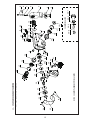
ITEM
BODY
360°SWIVEL J OINT
QUICK COUPLING
FIXING HOOK
360° SWIVEL REACTION ARM
SQUARE DRIVE
DRIVE RETAINER
NAME
SAFTY FIRST !!
Please read carefully follow instructions, warning and caution. Please observe the safety
precautions so that it can avoid personal and equipment to injury when you operate the
equipment. WREN is not responsible for any damage resulting from the operation of
irregularity.
Carefully inspect all components for shipping damage. If any shipping damage is found,
please notify carrier at once. Shipping damage is not covered by warranty. The carrier is
responsible for all repair or replacement cost resulting from damage in shipment.
The material of S series and H series Hydraulic Torque Wrenchs are Aluminium-Titanium
alloy and superhigh strength alloy steel for increased strength, intensity and durability of
the tool. High repeatability, a precise design is with accuracy ±3%.
DESCRIPTION
S series, Square Drive Torque Wrenches:
It is operating manual of S series and H series wrenches, please read carefully follow
instructions﹑warnings and cautions before using the tools.
①
② ③
④
⑤
⑥⑦
1

2
Do not use worn socket and square drive.
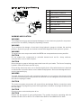
WARNING AND CAUTION
WARNING
WARNING
WARNING
CAUTION
CAUTION
WARNING
CAUTION
CAUTION
CAUTION
To avoid personal injury and equipment damages, be sure that every hydraulic component
can rated for 10,000PSI (700kg/cm²) Operating P ressure.
Try to minimum the danger of overl oad Using hydraulic gauge to indicate the working
pressure. Hydraulic gauge is a win dow to show what happened in the hydraulic system.
To replace the worn components with the WREN new components as soon as possible.
Do not subject the components to potential hazard such as fire, sharp surfaces,
extreme
heat or cold, or heave impact.
Never attempt to grasp a leaking pressurized hose with your hands. T he force of escaping
hydraulic fluid could cause serious injury.
Do not let the hose kink, twist, curl or bend so tightly that oil flow within the hose is blocked
or reduced.Do not use the hose to move attach ed equipment. Stress can damage the hose,
causing
personal injury.
To avoid personal injuries and equipment damages, do not remove the shroud of the
wrench.
Do not modify any com ponent of the wrench. Do not change the relief valve which
i
the swivel couplings.s inside
The incorrect system connection w ill cause failure and danger. Before connection, make
sure the swivel couplings being cle an. After application, the swivel couplings must be put
on
the dust caps.
Please use the socket of good perf or mance. The quality should be according with the
standard of ISO-2725 or ISO-1174 or DIN3129 or DIN3121 or ASME-B107.2/1995.
H series, Low Profile Torque Wrenches:
ITEM
NA ME
①
②
③
④
⑤
⑥
⑧
⑦
LOW PROFILE CASSETTE
PIN
POWER HEAD
QUICK COUPL ING
REACTION ARM
LINK PIN
RATCHET
360°×360° SWIVEL J OINT
⑨
360°SWIVEL J OINT
①
② ③ ④
⑤
⑥
⑧
⑦
H27/H54/H120/H210
①
②
③
④
⑨
⑥
⑧
⑦
H430

3
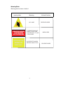
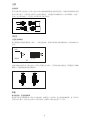
Warning Plate
Warning plate is shown in table 1
IF DRIVE STICKS OUT RIGHT,
IT'S SET FOR TIGHTEN.
LEFT. IT'S SET FOR LOOSE!
LOCK REACTION
ARM BEFORE
USING TOOL!
warning table
Meaning
Affixed Position
IF DRIVE STICKS OUT
RIGHT IT’S SET FOR
TIGHTEN.LEFT IT’S SET
FOR LOOSE!
WORK HEAD
REVERSE LEVER
NO HAND
LOCK REACTION ARM
BEFORE USING TOOL!
REVERSE LEVER

4
Bo lting
FOR M 1
NOTE:
BOLTING TIGH TENING FORCE RECOMME NTED CH ART
St rengt h Grade
4.8 6.8 8.8 10. 9
Min bre aking
st rength
3 92MPa 588MPa 784MPa 941MP a
Material
Q235(SS41) 35(S35C) 35CrMo(SCM3) 42CrMo(SCM4)
Thread KGM N .m
22 7 69 10 98 14 137 17 165
24 10 98 14 137 21 206 25 247
27 14 137 21 206 29 284 35 341
30 18 176 28 296 41 402 58 569
32 23 225 34 333 55 539 78 765
36 32 314 48 470 70 686 100 981
41 45 441 65 637 105 1029 150 1472
46 60 588 90 882 125 1225 200 1962
50 75 735 115 1127 150 1470 210 2060
55 100 980 150 1470 180 1764 250 2453
60 120 1176 180 1764 220 2156 300 2943
65 155 1519 240 2352 280 2744 390 3826
70 180 1764 280 2744 320 3136 450 4415
75 230 2254 350 3430 400 3920 570 5592
80 280 2744 420 4116 480 4704 670 6573
85 360 3528 530 5149 610 5978 860 8437
90 410 4018 610 5978 790 7742 1100 10791
95 510 4998 760 7448 900 8820
100 580 5684 870 8526 1100 10780
105 660 6468 1000 9800 1290 12642
110 750 7350 1100 10780 1500 14701
115 830 8143 1250 12250 1850 18130
120 900 8820 1400 13720 2250 22050
130 1080 10584 1650 16170 2500 24500
145 1400 13720 2050 20090
155 1670 16366 2550 24990
175 2030 19894 3050 29890
mm
Th e below s are DIN(F or you referen ce)
KGM N .m KGM N .m KGM N .m
The figure of the chart is the Max torque of the bolting, the recommended torque is 80% of chart
figure For instance:M52,strength grade is 8.8,the torque is 4704×80%=3763N.m
12. 9
117 6MPa
40 GrNiMoA(SNCM)
23 225
36 363
49 480
69 680
93 911
120 1176
180 1764
240 2352
250 2450
300 2940
370 3626
470 4606
550 5390
680 6664
850 8330
1050 10290
1350 13230
KGM N .m
14
16
18
20
22
24
27
30
33
36
39
42
45
48
52
56
60
64
68
72
76
80
85
90
100
110
120
M

5
OPERATION
The wrench and power pump are connected by a 700 BAR operating pressure, twin-line hose
assembly. Each end of the hose will have one male and one female connector to assure proper
interconnection between pump and wrench.
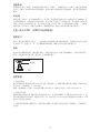
CONNECTING THE TOOL
FIG3
S SERIES
DRIVE DIRECTION CHANGE
To remove the square, disengage the drive retainer assembly by depressing the center round
button and gently pulling on the square end of the square drive. The square drive will slide easily
out.
To insert the drive in the tool, place the drive in the desired direction, engage drive and bushing
splines, then twist drive and bushing until ratchet spline can be engaged. Push drive through
ratchet. Depress drive retainer button, engage retainer with drive and release button to lock.
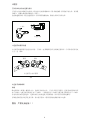
SETTING THE REACTION ARM
All WREN's Torque wrenches are equipped with a universal reaction arm. These reaction arms
are employed to absorb and counteract forces created as the unit operates. The reaction arm
should extend in the same direction of the square drive; However, slight adjustments may be
made to suit your particular application. The function of a reaction device is to hold the tool in
position against the forces generated to tighten or loosen bolts or nuts. Hydraulic wrenches
generate tremendous force. The reaction arm can be
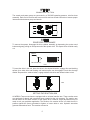
Squ are D rive
Drive Retai ner
Button
FIG4
FIG5
lossing tightening

6
positioned in numerous places within a 3600 circle. However, for the arm to be correctly
positioned, it must be set within a 900 quadrant of that circle. That quadrant is the area
located between the protruding square drive and the bottom of the housing away from the
swivel inlets. It will always be toward the lower half of the housing and on one side of the
housing when tightening and the other side when loosening.
SETTING THE SQUARE DRIVE FOR ROTATION
The position of the square drive when looking toward the shroud will determine if the tool
is set to tighten or loosen the nut. When the square drive extends to the left when looking
at the shroud with the inlets away from you, the tool is set to loosen the nut. When the
square drive extends to the right, the tool is set to tighten the nut. To change the direction
of rotation for MXTA series wrenches simply push the square drive into the housing until
the drive projects out the opposite side of the tool.
SETTING THE TORQUE
After determining the desired torque, use the torque conversion charts on page 5 to
determine the pressure that is necessary to achieve that torque.
1.Connect the tool to the power supply and turn the pump on.
2.Depress the advance remote control button causing the pressure to be shown on the
gauge.
3.Adjust the pressure by first loosing the nut that locks the pressure adjustment handle and
then rotate the handle clockwise to increase the pressure and counter clockwise to
decrease the pressure. When decreasing pressure, always lower the pressure below the
desired point and then bring the pressure gauge back up to the desired pressure.
4.When the desired pressure is reached, retighten the lock nut and cycle the tool again to
confirm that the desired pressure setting has been obtained.
FIG6
T Ha ndle
Lock ing Rin g
1.Place the square Drive in the socket, insert the socket retainer ring and pin, and place the
socket on the nut. Make certain the square drive and socket are the correct size for the nut
and that the socket fully engages the nut.
2.Position the reaction arm against an adjacent nut, flange or solid system
component.Make certain that there is clearance for the hoses and swivel couplings.Do not
allow the tool to react against the hoses, or swivel couplings.When reacting directly off the
tool body with reaction arm removed. Do not react off the exposed end plug spigot.
3.After having turned the pump on and presetting the pressure for the correct
torque,depress the remote control advance button to advance the piston assembly.
4.When the wrench is started, the reaction surface of the wrench or reaction arm will move
against the contact point and the nut will begin to turn. Once the piston reaches the end of
its stroke depress the remote control return button to retract the piston.
OPERATING THE WRENCH

7
5.Continue this cycling operation of advance and retract until the nut is no longer turning
and the pump gauge reaches the preset pressure. The piston rod will retract when the
retract button is pressed and under normal conditions, an audible “Click”will be heard as
the tool resets itself.
6.Continue to cycle the tool until it “Stalls”and the preset psi/torque has been attained.
7.Once the nut stops rotating, cycle the tool one last time to achieve total torque
H SERIES
CONNECTING THE POWER HEAD WITH THE LOW PROFILE CASSETTE
Both the square drive cartridge link and the low clearance ratcheting link are inserted and
removed from the power head in the same way. The “Hook”described by the link's drive
plates is inserted around the fixed pin of the power head, and the link is swung down to rest
along the base of the power head cylinder. At this point, the link pin holes of the power
head and link will align. Insert the link pin to secure.
Ratchet Link
Power head
Link Pin
FIG7
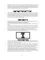
LOW PROFILE WRENCH POSITIONS
The position of the tool relative to the nut determines whether the action will tighten or
loose the nut. The power stroke of the piston assembly will always turn the ratchet hex to
ward the shroud
FIG8
Tightening Loosening
Drawing of Positions

After determining the desired torque, use torque conversion charts on page 5 to determine
the pressure that is necessary to achieve that torque.
1. Connect the tool to the power supply and turn the pump on.
2. Depress the advance remote control button causing the pressure to be shown on the
gauge.
3. Adjust the pressure by first loosing the nut that locks the pressure adjustment handle and
then rotate the handle clockwise to increase the pressure and counter clockwise to
decrease the pressure. When decreasing pressure,always lower the pressure below the
desired point and then bring the pressure gauge back up to the desired pressure.
4.When the desired pressure is reached, retighten the lock nut and cycle the tool again to
confirm that the desired pressure setting has been obtained.
SETING THE TORQUE
OPERATING THE WRENCH
1.Place the ratchet hex on the nut. Make certain it is the correct size for the nut and
that it fully engages the nut.
2.Position the reaction surface against an adjacent nut, flange or solid system
component. Make certain that there is clearance for the hoses, swivel, and inlets. Do
not allow the tool to react against the hoses, swivels or inlets.
3.After having turned the pump on and presetting the pressure for the correct
torque, depress the remote control advance button to advance the piston assembly.
If the notch in the piston rod did not engage the retract pin in the ratchet engage the
pin automatically during the first advance stroke.
4.When the low profile cassette is connected to the housing and the wrench is
started, the reaction surface of the wrench will move against the contact point and
the nut will begin to turn. Once the piston reaches the end of its stroke depress the
remote control return button to retract the piston.
5.Continue this cycling operation of advance and retract until the nut is no longer
turning and the pump gauge reaches the preset pressure. The piston rod will retract
when the retract button is pressed and under normal conditions, an audible
“Click”will be heard as the tool resets itself.
6.Continue to cycle the tool until it “Stall”and the preset psi/torque has been
attained.
7.Once the nut stops rotating, cycle the tool one last time to achieve torque.
8

9
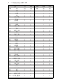
S SERIES HYDRAULIC TORQUE WRENCH PRESSURE-TORQUE CHART
7
8
9
10
11
12
13
14
15
16
17
18
19
20
21
22
23
24
25
26
27
28
29
30
31
32
33
34
35
36
37
38
39
40
41
42
43
44
45
46
47
48
49
50
51
52
53
54
55
56
57
58
59
60
61
62
63
64
65
66
67
68
69
70 1727
Model Number
Mpa N.m N.m N.m N.m N.m
S17 S45 S100 S150 S370
172
197
221
246
270
295
319
344
369
393
418
442
467
491
516
541
565
590
614
639
663
688
713
737
762
786
811
835
860
885
909
934
958
983
1007
1032
1057
1081
1106
1130
1155
1179
1204
1229
1253
1278
1302
1327
1351
1376
1401
1425
1450
1474
1499
1523
1548
1573
1597
1622
1646
1671
1695
452
517
581
646
710
775
839
904
969
1033
1098
1162
1227
1291
1356
1421
1485
1550
1614
1679
1743
1808
1873
1937
2002
2066
2131
2260
2195
2325
2389
2454
2518
2583
2647
2712
2777
2841
2906
2970
3035
3099
3164
3229
3293
3358
3422
3487
3551
3616
3681
3810
3745
3874
3939
4003
4068
4133
4197
4262
4326
4391
4455
4529
1006
1150
1293
1437
1581
1725
1868
2012
2156
2299
2443
2587
2731
2874
3018
3162
3305
3449
3593
3737
3880
4024
4168
4311
4455
4599
4743
4886
5030
5174
5317
5461
5605
5749
5892
6036
6180
6323
6467
6611
6755
6898
7042
7186
7329
7473
7617
7761
7904
8048
8192
8335
8479
8623
8767
8910
9054
9198
9341
9485
9629
9773
9916
10064
1497
1711
1925
2139
2352
2566
2780
2994
3208
3422
3636
3849
4063
4277
4491
4705
4919
5133
5346
5560
5774
5988
6202
6416
6630
6843
7057
7271
7485
7699
7913
8127
8340
8554
8768
8982
9196
9410
9624
9837
10051
10265
10479
10693
10907
11121
11334
11548
11762
11976
12190
12404
12618
12831
13045
13259
13473
13687
13901
14115
14328
14542
14756
14974
3699
4227
4756
5284
5813
6341
6870
7398
7926
8455
8983
9512
10040
10569
11097
11625
12154
12682
13211
13739
14268
14796
15324
15853
16381
16910
17438
17967
18495
19023
19552
20080
20609
21137
21666
22194
22722
23251
23779
24308
24836
25365
25893
26421
26950
27478
28007
28535
29064
29592
30120
30649
31177
31706
32234
32763
33291
33819
34348
34876
35405
35933
36462
36992

10
Model Number S17 S45 S100 S150 S370
ft.lbsft.lbsft.lbsft.lbs ft.lbspsi
1000
1200
1400
1600
1800
2000
2200
2400
2600
2800
3000
3200
3400
3600
3800
4000
4200
4400
4600
4800
5000
5200
5400
5600
5800
6000
6200
6400
6600
6800
7000
7200
7400
7600
7800
8000
8200
8400
8600
8800
9000
9200
9400
9600
9800
10000
S SERIES HYDRAULIC TORQUE WRENCH PRESSURE-TORQUE CHART
125
150
175
200
226
251
276
301
326
351
376
401
426
451
476
501
526
551
576
601
626
651
677
702
727
752
777
802
827
852
877
902
927
952
977
1002
1027
1052
1077
1102
1128
1153
1178
1203
1228
1253
329
395
461
527
593
658
724
790
856
922
988
1054
1119
1185
1251
1317
1383
1449
1514
1580
1646
1712
1778
1844
1909
1975
2041
2107
2173
2239
2305
2370
2436
2502
2568
2634
2700
2765
2831
2897
2963
3029
3095
3161
3226
3292
733
879
1026
1172
1319
1465
1612
1759
1905
2052
2198
2345
2491
2638
2784
2931
3078
3224
3371
3517
3664
3810
3957
4103
4250
4396
4543
4690
4836
4983
5129
5276
5422
5569
5715
5862
6008
6155
6302
6448
6595
6741
6888
7034
7181
7327
1090
1308
1527
1745
1963
2181
2399
2617
2835
3053
3271
3489
3707
3925
4143
4361
4580
4798
5016
5234
5452
5670
5888
6106
6324
6542
6760
6978
7196
7415
7633
7851
8069
8287
8505
8723
8941
9159
9377
9595
9813
10031
10249
10468
10686
10904
2694
3233
3772
4311
4850
5388
5927
6466
7005
7544
8083
8621
9160
9699
10238
10777
11316
11854
12393
12932
13471
14010
14549
15088
15626
16165
16704
17243
17782
18321
18859
19398
19937
20476
21015
21554
22092
22631
23170
23709
24248
24787
25325
25864
26403
26942

11
H SERIES HYDRAULIC TORQUE WRENCH PRESSURE-TORQUE CHART
7
8
9
10
11
12
13
14
15
16
17
18
19
20
21
22
23
24
25
26
27
28
29
30
31
32
33
34
35
36
37
38
39
40
41
42
43
44
45
46
47
48
49
50
51
52
53
54
55
56
57
58
59
60
61
62
63
64
65
66
67
68
69
70
Model Number
Mpa N.m N.m N.mN.m N.m N.m N.m N.m N.m N.m
H27 H54 H120 H210 H430
Bolt Size Range
1946 5060 2765 7080 5080 85105 70100 105115 80117 120175
262
299
337
374
412
449
487
524
561
599
636
674
711
749
786
823
861
898
936
973
1011
1048
1085
1123
1160
1198
1235
1273
1310
1347
1385
1422
1460
1497
1535
1572
1609
1647
1684
1722
1759
1797
1834
1871
1909
1946
1984
2021
2059
2096
2133
2171
2208
2246
2283
2321
2358
2395
2433
2470
2508
2545
2583
2625
306
350
393
437
481
525
568
612
656
699
743
787
831
874
918
962
1005
1049
1093
1137
1180
1224
1268
1311
1355
1399
1443
1486
1530
1574
1617
1661
1705
1749
1792
1836
1880
19
23
1967
2011
2055
2098
2142
2186
2229
2273
2317
2361
2404
2448
2492
2535
2579
2623
2667
2710
2754
2798
2841
2885
2929
2973
3016
3068
537
614
690
767
844
921
997
1074
1151
1227
1304
1381
1458
1534
1611
1688
1764
1841
1918
1995
2071
2148
2225
2301
2378
2455
2532
2608
2685
2762
2838
2915
2992
3069
3145
3222
3299
3375
3452
3529
3606
3682
3759
3836
3912
3989
4066
4143
4219
4296
4373
4449
4526
4603
4680
4756
4833
4910
4986
5063
5140
5217
5293
5372
603
689
775
861
948
1034
1120
1206
1292
1378
1464
1551
16
37
1723
1809
1895
1981
2067
2154
2240
2326
2412
2498
2584
2670
2757
2843
2929
3015
3101
3187
3273
3360
3446
3532
3618
3704
3790
3876
3963
4049
4135
4221
4307
4393
4479
4566
4652
4738
4824
4910
4996
5082
5169
5255
5341
5427
5513
5599
5685
5772
5858
5944
6037
1173
1341
1508
1676
1843
2011
2178
2346
2514
2681
2849
3016
3184
3351
3519
3687
3854
4022
4189
4357
4524
4692
4860
5027
5195
5362
5530
5697
5865
6033
6200
6368
6535
6703
6870
7038
7206
7373
7541
7708
7876
8043
8211
8379
8546
8714
8881
9049
9216
9384
9552
9719
9887
10054
10222
10389
10557
10725
10892
11060
11227
11395
11562
11737
1434
1639
1844
2049
2253
2458
2663
2868
3073
3278
3483
3687
3892
4097
4302
4507
4712
4917
5121
5326
5531
5736
5941
6146
6351
6555
6760
6965
7170
7375
7580
7785
7989
8194
8399
8604
8809
9014
9219
9423
9628
9833
10038
10243
10448
10653
10857
11062
11267
11472
11677
11882
12087
12291
12496
12701
12906
13111
13316
13521
13725
13930
14135
14349
2121
2424
2727
3030
3333
3636
3939
4242
4545
4848
5151
5454
5
757
6060
6363
6666
6969
7272
7575
7878
8181
8484
8787
9090
9393
9696
9999
10302
10605
10908
11211
11514
11817
12120
12423
12726
13029
13332
13635
13938
14241
14544
14847
15150
15453
15756
16059
16362
16665
16968
17271
17574
17877
18180
18483
18786
19089
19392
19695
19998
20301
20604
20907
21216
2312
2642
2973
3303
3633
3963
4294
4624
4954
5285
5615
5945
6275
6606
6936
7266
7597
7927
8257
8587
8918
9248
9578
9909
10239
10569
10899
11230
11560
11890
12221
12551
12881
13211
13542
13872
14202
14533
14863
15193
15523
15854
16184
16514
16845
17175
17505
17835
18166
18496
18826
19157
19487
19817
20147
20478
20808
21138
21469
21799
22129
22459
22790
23124
4379
5005
5630
6256
6881
7507
8132
8758
9384
10009
10635
11260
11886
12511
13137
13763
14388
15014
15639
16265
16890
17516
18142
18767
19393
20018
20644
21269
21895
22521
23146
23772
24397
25023
25648
26274
26900
27525
28151
28776
29402
30027
30653
31279
31904
32530
33155
33781
34406
35032
35658
36283
36909
3753
4
38160
38785
39411
40037
40662
41288
41913
42539
43164
43792
4848
5541
6233
6926
7618
8311
9003
9696
10389
11081
11774
12466
13159
13851
14544
15237
15929
16622
17314
18007
18699
19392
20085
20777
21470
22162
22855
23547
24240
24933
25625
26318
27010
27703
28395
29088
29781
30473
31166
31858
32551
33243
33936
34629
35321
36014
36706
37399
38091
38784
39477
40169
40862
41554
42247
42939
43632
44325
45017
45710
46402
47095
47787
48481

H SERIES HYDRAULIC TORQUE WRENCH PRESSURE-TORQUE CHART
Model Number
psi ft.lbs ft.lbs ft.lbs ft.lbs ft.lbs ft.lbs ft.lbs ft.lbs ft.lbs ft.lbs
H27 H54 H120 H210 H430
Bolt Size Range
1946 5060 2765 7080 5080 85105 70100 105115 80117 120175
191
229
267
305
343
382
420
458
496
534
572
611
649
687
725
763
801
840
878
916
954
992
1030
1069
1107
1145
1183
1221
1259
1298
1336
1374
1412
1450
1488
1527
1565
1603
1641
1679
1717
1756
1794
1832
1870
1908
1000
1200
1400
1600
1800
2000
2200
2400
2600
2800
3000
3200
3400
3600
3800
4000
4200
4400
4600
4800
5000
5200
5400
5600
5800
6000
6200
6400
6600
6800
7000
7200
7400
7600
7800
8000
8200
8400
8600
8800
9000
9200
9400
9600
9800
10000
223
267
312
357
401
446
490
535
579
624
669
713
758
802
847
892
936
981
1025
1070
1114
1159
1204
1248
1293
1337
1382
1426
1471
1516
1560
1605
1649
1694
1738
1783
1828
1872
1917
1961
2006
2051
2095
2140
2184
2229
391
469
548
626
704
782
860
939
1017
1095
1173
1252
1330
1408
1
486
1565
1643
1721
1799
1877
1956
2034
2112
2190
2269
2347
2425
2503
2581
2660
2738
2816
2894
2973
3051
3129
3207
3286
3364
3442
3520
3598
3677
3755
3833
3911
439
527
615
703
791
878
966
1054
1142
1230
1318
1405
1493
1581
1669
1757
1845
1933
2020
2108
2196
2284
2372
2460
2547
2635
2723
2811
2899
2987
3074
3162
3250
3338
3426
3514
3601
3689
3777
3865
3953
4041
4129
4216
4304
4392
854
1025
1196
1367
1538
1709
1880
2051
2221
2392
2563
2734
2905
3076
3247
3418
3588
3759
3930
4101
4272
4443
4614
4785
4
955
5126
5297
5468
5639
5810
5981
6152
6322
6493
6664
6835
7006
7177
7348
7519
7689
7860
8031
8202
8373
8544
1044
1253
1462
1671
1880
2089
2298
2507
2716
2925
3133
3342
3551
3760
3969
4178
4387
4596
4805
5014
5222
5431
5640
5849
6058
6267
6476
6685
6894
7102
7311
7520
7729
7938
8147
8356
8565
8774
8983
9191
9400
9609
9818
10027
10236
10445
1545
1854
2163
2472
2781
3090
3399
3708
4017
4326
4635
4944
5253
5562
5871
6180
6488
6797
7106
7415
7724
8033
8342
8651
8960
9269
9578
9887
10196
10505
1081
4
11123
11432
11741
12050
12359
12668
12977
13286
13595
13904
14213
14522
14831
15140
15449
1684
2021
2358
2694
3031
3368
3705
4042
4378
4715
5052
5389
5726
6062
6399
6736
7073
7410
7746
8083
8420
8757
9094
9430
9767
10104
10441
10778
11114
11451
11788
12125
12462
12798
13135
13472
13809
14146
14482
14819
15156
15493
15830
16166
16503
16840
3190
3827
4465
5103
5741
6379
7017
7655
8293
8931
9569
10206
10844
11482
12120
12758
13396
14034
14672
15310
15948
16586
17223
17861
18499
19137
19775
20413
21051
21689
22327
22965
23603
24240
24878
25516
26154
26792
27430
28068
28706
29344
29982
30619
31257
31895
3531
4237
4944
5650
6356
7062
7769
8475
9181
9887
10593
11300
12006
12712
13418
14125
14831
15537
16243
16949
17656
18362
19068
19774
20481
21187
21893
22599
23306
24012
24718
25424
26130
26837
27543
28249
28955
29662
30368
31074
31780
32486
33193
33899
34605
35311
12

Routine Maintenance and transport ofhydraulic torque wrench
Maintenance of the hydraulic torque wrench.
1 Before and after use, should check the screws are loose or not on the torque wrench,
if loose should be tightened. If you do not tighten, it may cause damage to the equipment.
、
2 Inside of the Torque Wrench, all parts should be regularly smear NLGI # 2, in complex
environmental conditions, should be cleaned and lubricated.
、
3 The coupler should be kept clean after work, tighten the dust cap to prevent dust entering
the hydraulic system failure to make the equipment damage.
、
4 Connecting devices, switch direction control valves, check the pressure with or without
exception.
、
5 Check for leakage, if a similar situation, please identify the reasons and processed.、
6 The parts of inside torque wrench are connected, if one part fails, it is bound to affect
other parts caused by wear, so regular inspection and maintenance are very important.
、
Hydraulic torque wrench noise declaration.
Hydraulic torque wrench noise value: 70db.≤
Hydraulic torque wrench transport information.
1 Handle with care.、
2 The shipment should be vertical upward, as shown in the figure 9-1.、
FIG 9-1
3 Product handling, generally using portable, car handling and lifting and moving,、
as shown in the figure 9-2.
FIG 9-2
13

14

15

16

17

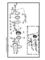
S series drawing
NOTE:30# can not part from the piston rod assembly
19
17
16
15
2728
29
30
31
32
33
34
35
34
36
37
38
39
40
41
26
25
24
1
2
15
16
17
18
9
8
7
6
3
4
5
2
20
21
22
23
14
13
12
11
10
S17、S45、S100、S150、S370
series
30# Part drawing
30-4
30-3
30-2
30-1
12
ページが読み込まれています...
ページが読み込まれています...
ページが読み込まれています...
ページが読み込まれています...
ページが読み込まれています...
ページが読み込まれています...
ページが読み込まれています...
ページが読み込まれています...
ページが読み込まれています...
ページが読み込まれています...
ページが読み込まれています...
ページが読み込まれています...
ページが読み込まれています...
ページが読み込まれています...
ページが読み込まれています...
ページが読み込まれています...
ページが読み込まれています...
ページが読み込まれています...
ページが読み込まれています...
ページが読み込まれています...
ページが読み込まれています...
ページが読み込まれています...
ページが読み込まれています...
ページが読み込まれています...
ページが読み込まれています...
ページが読み込まれています...
ページが読み込まれています...
ページが読み込まれています...
ページが読み込まれています...
ページが読み込まれています...
ページが読み込まれています...
ページが読み込まれています...
ページが読み込まれています...
-
 1
1
-
 2
2
-
 3
3
-
 4
4
-
 5
5
-
 6
6
-
 7
7
-
 8
8
-
 9
9
-
 10
10
-
 11
11
-
 12
12
-
 13
13
-
 14
14
-
 15
15
-
 16
16
-
 17
17
-
 18
18
-
 19
19
-
 20
20
-
 21
21
-
 22
22
-
 23
23
-
 24
24
-
 25
25
-
 26
26
-
 27
27
-
 28
28
-
 29
29
-
 30
30
-
 31
31
-
 32
32
-
 33
33
-
 34
34
-
 35
35
-
 36
36
-
 37
37
-
 38
38
-
 39
39
-
 40
40
-
 41
41
-
 42
42
-
 43
43
-
 44
44
-
 45
45
-
 46
46
-
 47
47
-
 48
48
-
 49
49
-
 50
50
-
 51
51
-
 52
52
-
 53
53


関連論文
その他のドキュメント
-
 Bitspower BPTA-ORFT16 インストールガイド
-
 Bitspower BPTA-ORFT12 インストールガイド
-
 Bitspower BPTA-ORFT14 インストールガイド
-
Electrolux EOC5851EAX Recipe book
-
Electrolux EOC5851FAX Recipe book
-
Philips DDL162CHKAC0/93 Product Datasheet
-
-
-
-
Philips HD4681/55 Product Datasheet


