
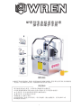
peration Manual
MP erises Hydraulic Pump
Hangzhou WREN Hydraulic Equipment Manufacturing Co.Ltd
Add:No 24 xingxing Road, Xingqiao, Yuhang district, Hangzhou, China
TEL: 0571-88110295 FAX:0571-88110210
code311100
Http://www.wrenchina.com

Catalog
Important Receiving Instructions …………………………………1
Precaution
Description
Warning!!!
Noise/Vibration And Transport information
Operation Instructions
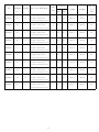
Explosion Of MP Series Pump
Explosion Of the Pump Module
Explosion Of the A Type Value Set Module
Explosion Of the B Type Value Set Module
Explosion Of the C Type Value Set Module
Explosion Of the D Type Value Set Module
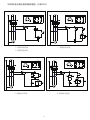
MP Series Electric Pump Control——
Circuit Principle Diagram(Single-Phase 220V)
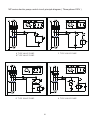
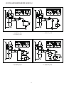
MP Series Electric Pump Control——
Circuit Principle Diagram(three-Phase 380V)
MP Series Electric Pump Control——
Circuit Principle Diagram(three-Phase 220V)
Hydraulic Principle
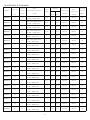
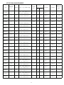
Specification & Parameter
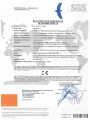
EC Declaration Of Conformity
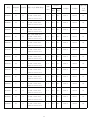
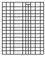
Trouble Shooting Guide Of Hydraulic Pump
Explosion Of the H Type Value Set Module
……………………………………………………2
………………………………………………3
………………………………………8-9
………………………………10
………………12
………………13
………………14
………………15
………………16
…………………17
…………………18
…………………19
……………………………21
………………………………11
………………………………………37
……………………………………………………4
………………………………………6
Maintenance and inspection
………………7
…………………………………22-36
…………………20
Warning Plate
……………………………………………………5

1
OPERATION AND MAINTENANCE MANUAL
FOR MP Series Pump
It is operating manual of MP series pump, please read carefully follow instructions
warnings and cautions before using the tools.
WREN Hydraulic
Safety Guide
The hydraulic of MP series pump's safe usage requires correct operation and
regular inspect. And the user is requested to follow always and carefully .
▲precaution to avoid direct loss in economic or property.
▲warning to avoid personal injury.
Please follow herein before!
When using, if something abnormal happens, please shut off the power
immediately, and then consult WREN or WREN`s agent.

2
FIG1
1.When using, do not permit any person stand at the oil output in order to avoid personal injury and
equipment damage. Please put the pump far away from the fire.
2.Make sure that the hose and quick coupler be connected before building up the pressure in order
to avoid hydraulic fluid spurting out to cause personal injury.
3.The maximum operating pressure of this pump is 70Mpa(10,000Psi),WREN has set up the
pressure to 70Mpa before selling this pump. Please do not adjust to a pressure higher than the
maximum pressure which WREN has not set.
4.If this pump is used for operating other equipments, make sure the maximum operating pressure
of the equipments will be less than 70Mpa. Please adjust the pressure to which the equipment need,
or else the equipment would be damaged.
5.Make sure the power of the pump is shut off before repairing it.
6.If the rapid release of pressure, lifting jack in the load will fall or spring open, may cause injuries;
please refer to WREN or WREN authorized agents, they will recommend you the right valve.
7.Please shut off the switch before starting power; if the switch is on, the pressure may increase.
8.Make sure the equipment be connected with ground to avoid electric shock.
9.Please do not change any part of the pump; if it must be changed, please inform WREN or Wren's
agent for help. Without allowance of WREN or its agent, any refit of it will be out of our warranty
range.
10.Please do not fill the pump reservoir with too much oil, otherwise, the pressure of the reservoir
will increase and the oil will spill over, so the reservoir will be broken and the environment will be
polluted.
11.Make sure the quick coupler is tightened; if the quick coupler is not tightened enough, the
equipment will not work normally; if it is a synchronic system, the problem may cause one or several
pieces of equipment out of order and the quick coupler may be broken and it may cause personal
injury or equipment damage.
12.Please stand away from the position where the hydraulic oil may be spurt out; hydraulic oil may
penetrate your hand and hurt you.
13.If the hydraulic oil splashed in your eyes, please immediately wash your eyes about 15 minutes
with clean water, then you must go to hospital for help right now.
14.Please do not touch the pressurized hose; if the hydraulic oil splashed out, it will cause serious
injury.
15.Hydraulic hose is easily spoiled fitting; you inspect the hose with eyes regularly and find no
problems, but the inner side may have crack and small hole; WREN suggests you should change
the hose regularly for
1.Only WREN hydraudic special oil available.
2.Do not use pressure regulate valve as relief valve.
3.The used hydraulic oil should be put away according to the antipollution ordinance.
PRECAUTION

3
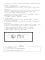
1 MP series electric pump adopts an integrated assembly; by the oil pump, control valve, fuel tank,
pneumatic motors, coolers, instrument consisting of an independent and complete hydraulic device,
has the advantages of small volume, light weight, simple structure, convenient operation, high work
pressure. Pump for high, low pressure oil pump and oil supply, it can obtain the larger oil output.
High pressure, low pressure pump by unloading overflow valve automatic no-load return oil, can
reduce the power consumption, and ( A ) export oil pressure is70 ~ 700Bar arbitrary regulation.
2 Electric hydraulic pump of the hydraulic oil used in:46# wear-resistant hydraulic oil.
3 Hydraulic electric pump working environment temperature: - 10~60 C
4 Use WREN high-pressure hose, quick coupler. The maximum working pressure of high pressure
hose WREN electric hydraulic pump used is 100Mpa, please use the selection and matching
pressure system.
5 This pump for use of hydraulic products, please consult the WREN engineer.
6 Please don't use the electric hydraulic pump near flame.
7 Please do not arbitrarily adjustable pressure regulating valve, in order to avoid the high pressure
caused by equipment damage and personal injury.
1.Oil storage tank: working with hydraulic oil storage, to ensure the normal work of the system ( must
have enough oil ), to provide the required pressure carrier system.
2.Cartridge valve blocks: a replaceable cartridge valve block ( A / B / C / D / H ) to achieve different
control.
3.Motor: provide power source (based on the use of the voltage, frequency selecting motor, see
specific parameters in the motor nameplate ).
4.Pump protection frame: installed in the storage tank, used for carrying, protection of hydraulic
pump station.
DESCRIPTION
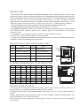
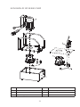
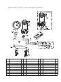
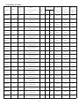
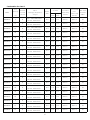
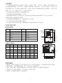
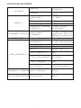
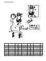
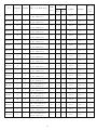
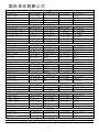
DESCRIPTION OF PARTS OF MP SERIES PUMP
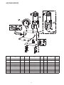
EXTERNAL DIMENSION AND OF MP SERIES PUMP
DESCRIPTIONS OF PARTS
ITEM NAME ITEM NAME
1
2
3
4
5
7
8
9
Storage tank
Valve block(A/B/C/D/H)
Electrical moto
Aluminum protection frame
Electronic control box
Cat's eye level gauge
Oil drainage hole
Fast joint
10
Six angle screws
Fuel tank cover
6
F
G
H
9
10
A
BC
E
D
5
6
7
8
1
2
3
4
ITEM MP04 MP08 MP13 MP18 MP24 MP32 MP56
A
B
C
D
E
F
G
H
254mm
430mm
353mm
200mm
240mm
377mm
244mm
290mm
254mm
480mm
403mm
200mm
240mm
379mm
244mm
299mm
314mm
480mm
405mm
260mm
300mm
463mm
320mm
400mm
314mm
510mm
435mm
260mm
300mm
463mm
320mm
400mm
314mm
570mm
495mm
260mm
300mm
463mm
320mm
400mm
460mm
510mm
440mm
460mm
505mm
662mm
600mm
645mm
522mm
600mm
530mm
505mm
522mm
662mm
600mm
645mm

4
5.Electronic control box: Built-in micro electronic control system, control the entire pump.
6.Ventilation hole : The realization of hydraulic oil discharge tank ( replacement of hydraulic oil used
in oil ); cover with ventilation holes, filling the oil cover, a filtering net is arranged to ensure that no
impurities into the tank; tightening oil cover ensure system of air discharged smoothly.
7.Liquid level gauge: Observation of hydraulic oil to ensure that the number, provide the best use of
oil; hydraulic oil below the oil standard1 /3 position, must add WREN pumping station hydraulic oil,
or may damage the pump station
8.Oil unloading hole: Plug G1/ 4", realize hydraulic oil discharge tank ( replacement of hydraulic oil
in use);
9.Fast joint : The realization of hydraulic oil output \ return oil function, fast connecting pipe built-in
type check valve;
10.Six angle screws: Sealing connecting tank
1.MP series electric pump is a double stage pump. High pressure outlet is provided with a pressure
relief valve, a low-pressure outlet pressure is 5 ~ 7Mpa, in 70Mpa state flow 0.8L / m.
2.70Mpa maximum operating pressure
3.Motor voltage:100 ~ 120V,200 ~ 240V,350 ~ 420V optional
4.Temperature: - 10~80 C
5.The 6storage tank ( tank specifications models ):4 ~ 65L7specifications
6. ISO VG 46# hydraulic oil
1.When operating, do not permit anyone stand at the oil output,The oil output must connect other
components when adjusting the pressure.
2.When using, do not overpass the max operating pressure.
3.If need to check motor tank, please shut off the pump.
4. When working, the oil back to oil reservoir may add the pressure. If open the cover plate,
unnecessary injury and damage will happen.
5.Proihbit to operate without oil
6.Keep the pump clean,clean especially the oil inlet, quick couplers.
7.Suggestion: in the condition of not using the pump always, please remember to replace the
hydraulic oil
CHARACTERISTIC
WARNING!!!

5
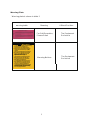
Warning Plate
Warning plate is shown in table 1
warning table
Meaning
Affixed Position
! WARNING
To help avoid personal injury,read the operating
instructionsbeforeusingthispump.
Disconnect the power supply before any
maintenanceisperformedonthispump.All
electricalworkmustbedonebyaqualified
electrical.
Operators of this hydraulic power supply unit
oroperationsof equipmentpoweredbythis
unit mustbeknowledgeableof hydraulic
equipmenthazardsifanyhydraulic
equipmentisusedi
ncorrectly.
Hy
draulic fluid recommended in operating
instructionsmustbeusedinthispump.
Do not use pump in any type of explosive,
flammable,orgasenvironment.
Escaping hydrauic fluid under pressure can
havesufficientforcetopenetratetheskin
andcauseseriouspersonalinjury.Ifyouare
injuredbyescapinghydraulicfluid,seek
medicalattentionimmediately.Seeoperating
instructions for further precautions to help
prevent thepossibilityofhazardsoccurring
duetoescapinghydraulicfluid.
The Equipment
Enclosure
The Equipment
Enclosure
Warning Notices
For Saft Operation,
Please Read

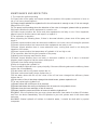
1. The inspection before operating
(1).Please shut off the pump and inspect whether the position of the power connection is loose or
not. If it is loose, please tighten it.
(2).Please inspect whether the hydraulic oil in the oil reservoir is enough or not, if it is not enough,
please fill the oil in time.
(3).The pump is still working when the direction of the valve is changed, please build up pressure
and inspect whether the whole equipment is normal or not.
(4).Please inspect whether the house and other equipments are leaky or not, if this happened,
please inspect to find the reason and repair it or replace it.
2.The inspection in operation
When inspecting the following items, if there is abnormal situation, please shut off the pump and
repair it.
(1)Please inspect whether there are abnormal condition or not in the course of raising the pressure.
(2)Please inspect whether the houses and other equipments are leaky or not.
(3)Please inspect whether there is some abnormal noise, rocking and smell or not during the
operation of the motor.
(4)Please inspect whether the temperature of hydraulic oil is too high or not.
3.The inspection after finishing the operation of the pump.
(1)Making sure the pump must be turn down.
(2)Please inspect whether there are leaky or abnormal condition or not. If there is abnormal
situation,please inspect to find the reason and repair it
(3)Please clean it after using the pump.
4.Refer to changing the hydraulic oil
The oil should be replaced once a year principally. If there are following abnormal conditions, please
replace the oil immediately.
(1)If dust mixes with the oil, please replace the oil.
(2)If there is abnormal smell, please replace the oil.
(3)If the water mixes with the oil, the colour of the oil has been changed into milkiness, please
replace the oil.
(4)If the colour of the oil has been changed into black-brown, please replace the oil.
5.The way replacing the hydraulic oil
(1)Please loosen the oil filler port of oil reservoir.
(2)Please take down the screw on the flank of the oil reservoir, let hydraulic oil out.
(3)Please clean the inner and filter of the oil reservoir.
(4)Please install the screw and fill the oil reservoir with the hydraulic oil.
WARNING: If the oil splashes into your eyes, please wash with clean water for at least 15 minutes,
and Then see doctor immediately. If the oil splashes to your skin, please wash it with clean water
and soap.
WARNING: Waste hydraulic oil bellows to industrial waste, it should be dealt with by special
companies.
MAINTENANCE AND INSPECTION
6

7
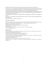
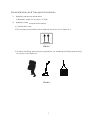
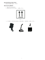
Noise/Vibration And Transport information
1、 Hydraulic pump noise declaration
1) Hydraulic pump
noise value: 70db
≤
2、
transport information.
Hydraulic pump
1) Handle with care.
2)The shipment should be vertical upward, as shown in the figure 9-1.
3) Product handling, generally using portable, car handling and lifting and moving,
.as shown in the figure 9-2
FIG 9-1
FIG 9-2

8
OPERATION INSTRUCTIONS
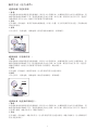
The type A valve block pump (hand double action ):
1 .Ready
Starting motor before cleaning and inspection of the connector, and then injected into a special
hydraulic oil, in ensure the use of pressure in the pressure range, connected by a hose pump and
operating tools, check whether the correct connection of safety, such as incorrect, hydraulic pump
can not work normally. Check the manual reversing valve to switch the direction shown, according to
working need adjusting valve.
2 .Boot
Turn on the power, start the motor, regulating valve to the forward ( backward ) position, pressure is
increased to the desired pressure value, manual reversing valve is pressure in.
3 .Removing
After the work is finished, stop the motor, cut power off, the manual reversing valve, remove hose.
The type B valve block pump (hand single action ):
1 .Ready
Starting motor before cleaning and inspection of the connector, and then injected into a special
hydraulic oil, in ensure the use of pressure in the pressure range, connected by a hose pump and
operating tools, check whether the correct connection of safety, such as incorrect, hydraulic pump
can not work normally. Check valve manually locking, according to working need adjusting valve
manually ( tighten packing, loosen the pressure relief ).
2 .Boot
Turn on the power, start the motor, is a manual valve, pressure is increased to the desired pressure
value and holding pressure.
3 .Removing
After the work is finished, the stop of the motor, cut off the power supply, loosen the hand valve
pressure relief, remove hose.
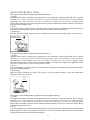
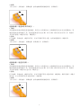
The type C valve block pump ( electric control single packing):
1 .Ready
Starting motor before cleaning and inspection of the connector, and then injected into a special
hydraulic oil, in ensure the use of pressure in the pressure range, connected by a hose pump and
operating tools, check whether the correct connection of safety, such as incorrect, hydraulic pump
can not work normally. Remote control switch has two buttons ( the A key to move the boost, B key
to move the pressure relief ).
2 .Boot
Turn on the power, the motor is started, the A key to move the pressure, pressure is increased to the
desired pressure value and pressure, the B key to move the pressure relief, pressure is reduced to
a desired pressure value and holding pressure.
Pressure Hold
at Middle Position
hand
valve

A
B
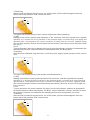
The type D valve block pump ( electric control single action without packing):
1 ready
Starting motor before cleaning and inspection of the connector, and then injected into a special
hydraulic oil, in ensure the use of pressure in the pressure range, connected by a hose pump and
operating tools, check whether the correct connection of safety, such as incorrect, hydraulic pump
can not work normally. Remote control switch has two buttons ( the A key to move the boost, the B
key spare).
2 boot
Turn on the power, the motor is started, the A key to move the pressure, pressure is increased to the
desired pressure value, when the button is loosened and relief, the B key spare.
3 removing
After the work is finished, stop the motor, cut off the power supply, system pressure relief, remove
hose.
3 .Removing
After the work is finished, stop the motor, cut off the power, pull the electromagnetic valve top
button and let the pressure relief, remove the hose.
A
B
The type H valve block pump ( electronically controlled dual role ):
1 ready
Starting motor before cleaning and inspection of the connector, and then injected into a special
hydraulic oil, in ensure the use of pressure in the pressure range, connected by a hose pump and
operating tools, check whether the correct connection of safety, such as incorrect, hydraulic pump
can not work normally. Remote control switch has two buttons ( the A key to move left to right out,
B key instead ).
2 boot
Turn on the power, the motor is started, the A key to move the pressure, pressure is increased to
the desired pressure value and pressure, the B key. Hose connected in reverse, the B key to move
the pressure, pressure is increased to the desired pressure value and pressure, the A key.
3 removing
After the work is finished, stop the motor, cut off the power, tpull the electromagnetic valve top
button and let the pressure relief, remove hose.
A
B
9

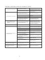
TROUBLE SHOOTING GUIDE OF HYDRAULIC PUMP
The pump can't be started
The voltage isn't suitable
Checked the input air, switch and
distribution box and so on, and
connect the air.
Confirming whether the v oltage
is suitable for the pump's need
The power hasn't be connected
The system has no pressure
The quick coupler hasn't be
connected to the correct position
Take down and reinstall it
No oil in the oil reservoir
Fill in oil
Not enough oil in the oil reservoir
Fill in oil
If the syst
em has a throttle and
hand single-direction valve, please
check if the valve are open
Open the throttle and hand
single-direction valve, and
make sure the system is a circle
After reinstalling the quick
coupler,the system has no
pressure
The quick coupler can't be connected
to the correct position, which causes
no pressure in the system
Take down the quick coupler, check
if the boll is elastic with a rod, if it can't
m
ove, please knock it with a hammer to
eliminate the mist hydraulic oil
Leakage in the quick coupler The o ring and escape have worn out Replace the quick coupler
The pressure can't reach to
the set pressure
The relief valv e is adjusted
too low
Check with the gauge, and adjust the
relief valve to the system set pressure
Oil is mixed with water
Change oil
Not enough oil in the reservoir
Fill in oil
Repeat operating the system with no
load for several times to eliminate the air
Suck in air to the system
The throttle and hand single-direction
valve haven't been tightened
Locking valve
The throttle and hand si
ngle-direction
valve haven't been adjusted to the
correct position
Adjust to the correct position
The throttle and hand single-direction
valve have broken
Replace the valve
There is foreign matter in
the oil
Wash the pump valve and
change clean oil
When using under static pressure,
the pressure reduces slowly
The seal is out of control, please
check all the seal
Replace the seal
Pump during operation with
strong noise
Radial plunger pump bearing
damage
Replace the radial plunger
10

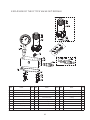
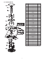
EXPLOSION OF MP SERIES PUMP
ITEM
1
2
3
The tank module
Pump module
Oil return pipe(1)
Petroleum Pipeline
Hydraulic control valve block
Electric control valve block
4
5
6
NAME NAMEITEM
11

12
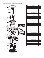
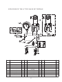
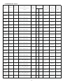
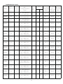
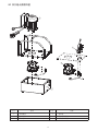
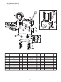
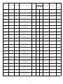
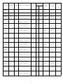
EXPLOSION OF THE PUMP MODULE
ITEM
2.1
2.2
2.3
2.4
2.5
2.6
2.7
2.7.1
2.7.2
2.7.3
2.7.4
2.8
2.9
2.9.1
2.9.2
2.9.3
2.9.4
2.9.5
2.10
2.11
2.12
2.13
2.14
2.15
2.16
2.17
2.18
2.19
2.20
2.21
2.22
2.23
2.24
2.25
2.26
Seal
Deep groove ball bearing
Bearing
Screw
Pump flange
The pump body set
Unloading valve
Unloading valve body
Ring
O Ring
O Ring
Overpressure valve
Check valve
The one-way valve body
Ring
O Ring
O Ring
Ring
Separation type pump body
Plug
Filter plate
Screw
Deep groove ball bearing
The circlip for shaft
Empty of elastic ring
Deep groove ball bearing
Plunger 1
Plunger 2
Pin
Bearing end plate
Elastic washer
Screw
Connecting piece
Screw
Fitter
1
1
1
4
1
1
1
1/1
1/1
1/1
1/1
1
2
1/1
1/1
1/1
1/1
1/1
1
1
6
1
1
1
1
1
4
2
1
1
1
1
1
12
1
NAME NUM

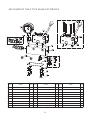
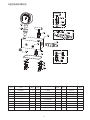
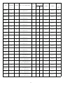
ITEN
5.1
5.2
5.3
5.3.1
5.3.2
5.3.3
5.3.4
5.4
5.5
5.6
5.7
The WA connection block
Plug
Check valve
Valve body
Ring
O Ring
O Ring
Ring NPT1/4
Ring
Flat washer
Elastic washer
Screw
Pressure regulating valve
Valve bidy
O Ring
O Ring
Pressure gauge
Reversing valve
Reversing valve body
O Ring
Screw
1
7
1
1/1
1/1
1/1
1/1
1/1
1/1
4/1
4/1
4
1
1
1/1
1/1
1
Pressure meter joint 1
1
1/1
4/1
4/1
5.8
5.9
5.9.1
5.9.2
5.9.3
5.10
5.11
5.12
5.12.1
5.12.2
5.12.3
NAME
NUM NUM NUMNAME NAMEITEN ITEN
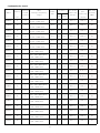
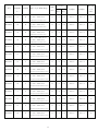
EXPLOSION OF THE A TYPE VALVE SET MODULE
13

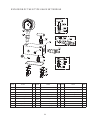
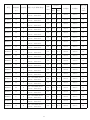
ITEN
5.1
5.2
5.3
5.3.1
5.3.2
5.3.3
5.3.4
5.4
5.5
5.6
5.7
The WA connection block
Plug
Check valve
Valve body
Ring
O Ring
O Ring
Ring NPT1/4
Ring
Flat washer
Elastic washer
Screw
Pressure regulating valve
Valve bidy
O Ring
O Ring
Pressure gauge
Stop valve
Stop valve body
O Ring
O Ring
1
7
1
1/1
1/1
1/1
1/1
1
1
4/1
4/1
4
1
1
1/1
1/1
1
Pressure meter joint 1
1
1/1
1/1
1/1
5.8
5.9
5.9.1
5.9.2
5.9.3
5.10
5.11
5.12
5.12.1
5.12.2
5.12.3
NAME
NUM NUM NUMNAME NAMEITEN ITEN
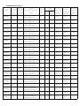
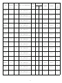
EXPLOSION OF THE B TYPE VALVE SET MODULE
14

ITEN
5.1
5.2
5.3
5.3.1
5.3.2
5.3.3
5.4
5.5
5.6
5.7
The WC connection block
Plug
Pressure regulating valve
Valve body
O Ring
O Ring
Ring NPT1/4
Sealing ring
Flat washer
Elastic washer
Screw
Check valve
Check valve bidy
Ring
O Ring
Pressure gauge
Electromagnetic valveVG-3)
Electromagnetic valve body
O Ring
O Ring
1
4
1
1/1
1/1
1/1
1
1
4
4
4
1
1/1
1/1
1/1
1
Pressure meter joint 1
1
1/1
1/1
2/1
5.8
5.9
5.9.1
5.9.2
5.9.3
O Ring 1/15.9.4
5.10
5.11
5.12
5.12.1
5.12.2
5.12.3
NAME
NUM NUM NUMNAME NAMEITEN ITEN
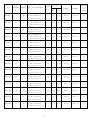
EXPLOSION OF THE C TYPE VALVE SET MODULE
15

ITEN
5.1
5.2
5.3
5.3.1
5.3.2
5.3.3
5.4
5.5
5.6
5.7
The WC connection block
Plug
Check valve
Valve body
O Ring
O Ring
Ring NPT1/4
Sealing ring
Flat washer
Elastic washer
Screw
Check valve
Check valve bidy
Ring
O Ring
Pressure gauge
Electromagnetic valve(VGZ-3)
Electromagnetic valve body
O Ring
O Ring
1
4
1
1/1
1/1
1/1
1
1
4
4
4
1
1/1
1/1
1/1
1
Pressure meter joint 1
1
1/1
1/1
2/1
5.8
5.9
5.9.1
5.9.2
5.9.3
O Ring 1/15.9.4
5.10
5.11
5.12
5.12.1
5.12.2
5.12.3
NAME
NUM NUM NUMNAME NAMEITEN ITEN
EXPLOSION OF THE D TYPE VALVE SET MODULE
16

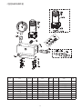
EXPLOSION OF THE H TYPE VALVE SET MODULE
ITEN
5.1
5.2
5.3
5.3.1
5.3.2
5.3.3
5.3.4
5.4
5.5
5.6
5.7
The WH connection block
Plug
Check valve
Valve body
Ring
O Ring
O Ring
Ring NPT1/4
Ring
Flat washer
Elastic washer
Screw
Pressure regulating valve
Valve bidy
O Ring
O Ring
Electromagnetic valve
Pressure gauge
Valve body
O Ring
O Ring
1
5
1
1/1
1/1
1/1
1/1
2
1/1
4
4
4
1
1/1
1/1
1/1
1
1
1
1/1
4/1
4/1
5.8
5.9
5.9.1
5.9.2
5.9.3
5.10
5.11
5.11.1
5.11.2
5.11.3
NAME
NUM NUM NUMNAME NAMEITEN ITEN
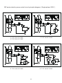
17

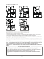
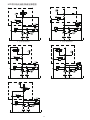
A TYPE VALVE PUMP
B TYPE VALVE PUMP
C TYPE VALVE PUMP
D TYPE VALVE PUMP H TYPE VALVE PUMP
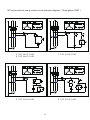
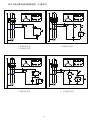
MP series electric pump control circuit principle diagram ( Single-phase 220V )
(电机线路图)
~
~
~
~
~
(电机线路图)
~
~
~
~
~
~
(电机线路图)
~
~
~
~
~
(电机线路图)
~
~
~
~
18
ページが読み込まれています...
ページが読み込まれています...
ページが読み込まれています...
ページが読み込まれています...
ページが読み込まれています...
ページが読み込まれています...
ページが読み込まれています...
ページが読み込まれています...
ページが読み込まれています...
ページが読み込まれています...
ページが読み込まれています...
ページが読み込まれています...
ページが読み込まれています...
ページが読み込まれています...
ページが読み込まれています...
ページが読み込まれています...
ページが読み込まれています...
ページが読み込まれています...
ページが読み込まれています...
ページが読み込まれています...
ページが読み込まれています...
ページが読み込まれています...
ページが読み込まれています...
ページが読み込まれています...
ページが読み込まれています...
ページが読み込まれています...
ページが読み込まれています...
ページが読み込まれています...
ページが読み込まれています...
ページが読み込まれています...
ページが読み込まれています...
ページが読み込まれています...
ページが読み込まれています...
ページが読み込まれています...
ページが読み込まれています...
ページが読み込まれています...
ページが読み込まれています...
ページが読み込まれています...
ページが読み込まれています...
ページが読み込まれています...
ページが読み込まれています...
ページが読み込まれています...
ページが読み込まれています...
ページが読み込まれています...
ページが読み込まれています...
ページが読み込まれています...
ページが読み込まれています...
ページが読み込まれています...
ページが読み込まれています...
-
 1
1
-
 2
2
-
 3
3
-
 4
4
-
 5
5
-
 6
6
-
 7
7
-
 8
8
-
 9
9
-
 10
10
-
 11
11
-
 12
12
-
 13
13
-
 14
14
-
 15
15
-
 16
16
-
 17
17
-
 18
18
-
 19
19
-
 20
20
-
 21
21
-
 22
22
-
 23
23
-
 24
24
-
 25
25
-
 26
26
-
 27
27
-
 28
28
-
 29
29
-
 30
30
-
 31
31
-
 32
32
-
 33
33
-
 34
34
-
 35
35
-
 36
36
-
 37
37
-
 38
38
-
 39
39
-
 40
40
-
 41
41
-
 42
42
-
 43
43
-
 44
44
-
 45
45
-
 46
46
-
 47
47
-
 48
48
-
 49
49
-
 50
50
-
 51
51
-
 52
52
-
 53
53
-
 54
54
-
 55
55
-
 56
56
-
 57
57
-
 58
58
-
 59
59
-
 60
60
-
 61
61
-
 62
62
-
 63
63
-
 64
64
-
 65
65
-
 66
66
-
 67
67
-
 68
68
-
 69
69


関連論文
その他のドキュメント
-
Greenlee PVA0021, PVA0022 Hydraulic Control Valves-Chinese ユーザーマニュアル
-
-
Wacker Neuson RT56-SC2 ユーザーマニュアル
-
Graco 311796B GH130, 200, 230 & 300 Hydraulic Sprayers 取扱説明書
-
WIKA CPB5800 取扱説明書
-
DURKOPP ADLER 251-140042 Manual Motor
-
FLEXTAILGEAR HT-767 ユーザーマニュアル
-
TOA E-84S CN ユーザーマニュアル
-
-
REXON MX130R 取扱説明書