Wren KLW4000D Operation and Maintenance Manual
- タイプ
- Operation and Maintenance Manual

.
KLW4000
Operation And Maintenance Manual
Of KLW4000 Series Hydraulic Pump

1.When using, do not permit any person stand at the oil output in order to avoid personal injury and
equipment damage. Please put the pump far away from the fire.
2.Make sure that the hose and quick coupler be connected before building up the pressure in order to
avoid hydraulic fluid spurting out to cause personal injury.
3.The maximum operating pressure of this pump is 70Mpa(10,000Psi),WREN has set up the pressure to
70Mpa before selling this pump. Please do not adjust to a pressure higher than the maximum pressure
whichWREN has not set.
4.If this pump is used for operating other equipments, make sure the maximum operating pressure of the
equipments will be less than 70Mpa. Please adjust the pressure to which the equipment need, or else the
equipment would be damaged.(Referrence content 5)
5.Make sure the power of the pump is shut off before repairing it.
6.Please shut off the switch before starting power; if the switch is on, the pressure may increase.
7.Make sure the equipment be connected with ground to avoid electric shock.
8.Do not start the pump without oil in tank.
9.Please do not change any part of the pump; if it must be changed, please inform WREN or Wren's agent
for help. Without allowance of WREN or its agent, any refit of it will be out of our warranty Range.
10.Please do not fill the pump reservoir with too much oil, otherwise, the pressure of the reservoir will
increase and the oil will spill over, so the reservoir will be broken and the environment will be polluted.
11.When the pump works,the pressure may be increased with the returning oil.If the oil filler cop is opened
at the moment, this may cause the injury.
12.Make sure the quick coupler is tightened; if the quick coupler is not tightened enough, the equipment
will not work normally; if it is a synchronic system, the problem may cause one or several pieces of
equipment out of order and the quick coupler may be broken and it may cause personal injury or equipment
damage.
13.Make sure to reep the pump in cleaning.
14.Please stand away from the position where the hydraulic oil may be spurt out; hydraulic
oil may penetrate your hand and hurt you.
15.If the hydraulic oil splashed in your eyes, please immediately wash your eyes about 15
minutes with clean water, then you must go to hospital for help right now.
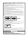
PICTURE 2
16.Please do not touch the pressurized hose; if the hydraulic oil splashed out, it will cause serious
injury.
17.Hydraulic hose is easily spoiled fitting; you inspect the hose with eyes regularly and find no problems,
but the inner side may have crack and small hole; WREN suggests you should change the hose regularly
for smoothing use.When using,try to avoid bending the hose in sudden.
11

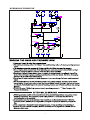
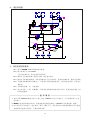
1. Oil reservoir: To store hydraulic oil, make sure the reservoir enough oil to keep the pump work
normally.
2.The adjusting pressure regulator: Adjust this valve for setting the working pressure of power pack
(the)max working pressure has been locked before sales, please do not change the locked pressure
at any time.
3. Pressure gauge: it’s effects 0-100Mpa, showing the working pressure of the power pack.
4. Frame for protecting: it is fixed on motor for carrying conveniently.
5. Motor: provide power.
6. Radiator: to exclude the heat, ensure the operating time and life of the pump.
7. Oil level measurer: it can help us know the oil level, when the oil less than the1/3 of total, please
Fill the especial oil for hydraulic tools of WREN.
8. Release oil port: G1/4.
9. Control system: the integrated electric equipment of the pump.
10. Cover plate for oil tank: seal the oil tank and install the parts of power pack.
11. Solenoid valve: Its function is output oil when the pressure is very high, control the flow when
return oil, and soon. It can be set up the maximum pressure and protect system to work normally at the
pressure set up. The threads of oil output port is NPT1/4”.
12. Quick coupler : it’s function is output oil when the pressure is very high, control the flow when
return oil , and so on, it can be set up the maximum pressure and protect system to work normally at
the pressure set up, the threads of oil output port is NPT 1/4”
13. Valve block: control oil driving in and out; make sure the hydraulic system can be worked normally
under the pressure to be set up.
14. Oil filling port: To be used for filling and replacing oil.
2

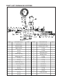
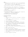
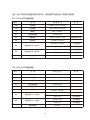
EXTERNAL DIMENSION AND DESCRIPT ION OF PARTS
Item Description Item Description
1 8
2 9
3 10
4 11
5 12
6 13
7 14
Oil reservoir
Adjusting pressure regulator
Pressure gauge
Frame for protecting
Motor
Radiator
Oil lever measurer
Release oil port
control system
Cover plate for oil tank
Solenoid valve
Quick Coupler
Valve block
Oil filling port
3

0.8
7
/200-240V 60HZ 0.9KW /100-130V 60HZ 0.9KW
27
,And cover on the dust cap.
200-240
4

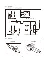
1.Ready:
1.1 KLW4000hydraulic power pump is designed for hydraulic torque wrench. There is a 2-way, 4-
position solenoid operated direction control valve on the pump, port A is high pressure point, it can
export the oil at the high pressure, and port B is low pressure point which can output the oil at the
low pressure.
1.2 Please loosen the high-pressure valve for adjusting pressure before operating.
2.Adjust the pressure:
2.1 Please connect the power and push the switch at the position of “ON”. Then press the lock
button make the power pack working, then the power pack will output the low-pressure.
2.2 Please press the retract button on the controller and adjust the pressure unit the working
Plessure reach to what you need, and then loosen the retract button on the controller.
3. Operation:
3.1 Please press down the retract button on the controller, the pump output. The high pressure,
torque wrench works;Loosen from the retract button, the pump output the low pressure, the
torque wrench retracts; press down the lock button, the button retracts, the pump stops.
3.2 After operating, please turn off the power. Then press the rubber button on the top of solenoid
operated direction control valve in order to release the pressure in hoses and equipments,then you
can take down the hose and cover the safety cap for the quick couplers.
Attention: First time to use or after service, please try several time to operate without any
loading, this ca eliminate the in system.
Adjust
pressure
Lock button
Retract button
5

1
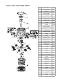
Valve block
Female coupler
O-ring
1
4
O-ring O-ring
1
5
O-ring
Retaining ring
O-ring
1
8
O-ring
9
O-ring O-ring
2
O-ring
1
12
O-ring
13
O-ring O-ring
1
15
O-ring
16
O-ring
1
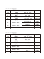
ITEM
DESCRIPTION QTY
ITEM
DESCRIPTION QTY
2
1
18
1
3
1
19
6
2
22
2
7
2
23
10
2
26
11
2
27
1
14
1
30
1
1 31 1
1
29
1
28
1
2
25
2
24
4
2
21
1
2
20
1 17 1
Male coupler
Retaining ring
Retaining ring
Reversing valve
Adjusting valve
Retaining ring
Unilateralism valve
Adjusting valve
Casing screw
Screw
Connector
Connector
Gauge
Solenoid valve
PART LIST FORVALVE SYSTEM
6

Bearing
O-ring
O-ring
O-ring
O-ring
Retaining ring
Retaining ring
Retaining ring
Unilateralism valve
Safety valve
Release valve 2
Clip
Bearing
Circle
Piston 1
Piston 2
Piston 3
Pin
Plate
Screw
Connecting plate
Filter
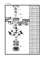
PART LIST FOR PUMP HEAD
1/set
1/set
2
1/set
1
1
1
1/set
1/set
1
1/set
1/set
1/set
1/set
1
1/set
1/set
1/set
1/set
1
1
1
1
4
2
2
1
1
1
1
1
16
1
5-2
7
7-1
2
3
4
5
5-1
5-3
5-4
6
7-2
7-3
7-4
7-5
8
8-1
8-2
8-3
8-4
9
10
11
12
13
14
15
16
17
18
19
20
21
22
23
1
Check Valve
Relief Valve
Seal gasket
1
1
1
ltem
Description
QTY
Bearing
Bearing pole
Pump head
Release valve
Retaining ring
O-ring
O-ring
Screw
Screw
Relief Valve
Metal Retaining Ring
7

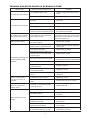
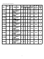
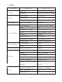
Mal function Reason for caused malfunction Solution
The pump can not be started
Un-suitable power source
Confirm if the power meets pump’s
need
The power is not connected
Check the power
The system has no pressure
The coupler is not connected
properly
Re-install
No oil in the tank Fill oil
Not enough oil
Fill oil
Check if flow control valve, single-
direction valve in the system is open
Open the flow control valve to ensure
the system is connected
The system has no pressure
after reinstall the couplers
The couplers is not connected in
the properly position
Uninstall the couplers, check if the steel
roll is elastic with a rod, if it can not move
please knock it with hammer to elimina
te the mist hydraulic oil.
Leaking in the couplers
The o-ring, retaining ring worn
out in the couplers
Replace the couplers
The pressure for high-pressure
leaking valve is adjusted too low
Please check the gauge, adjust it to
rated value
Oil is mixed with water
Replace the oil, please
Ball steel in pressure relief valve
may be broken or the valve seat
may be frayed
Replace them,please
Air may be sucked into the system
Repeat operating the system with no
load for several times to eliminate air
The leaking valve may be frayed
Replace it, please
High-pressure leaking valve may
not be tightened
Tighten it, please
The o-ring for high-pressure leaking
valve may be broken
Replace it, please
There may be some inclusion into
the oil
Wash the power pack valve and
replace oil
The system pressure can
not reach to the rated
pressure
There is a strong noise
when the power pack is
operated
The bearing may be broken
Air may be mixed into this power
pack
Replace it, please
Exhaust the air from the system
When using under static
pressure, the pressure
reduces slowly
The seal is out of control,please
check all the seal
Replace the seal
Piston or spring may be broken
Change them, please
Leaking may be happened at
brushfire position
Tighten the couplers and replace
the seals
Oil lever may be too low
High-pressure system may not
eliminate the oil fully
Please try several times without load
before using
Too low oil temperature may make
lead to suck oil difficultly
Control the temperature at -10℃ to
60℃ ,please
Oil temperature may be too high
that cause the damage of pump
If so, the power pack need to be
replaced with new one
High-pressure flux is not
enough
Fill the oil,please
TROUBLE SHOOTING GUIDE OF HYDRAULIC PUMP
8

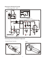
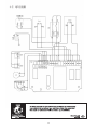
HYDRAULIC PRINCIPLE
70
24~26
9

Drawing for Electrical Principle
Selecting Chart for Electrical Component
1 Pump voltage 100V – 220V
Big type
Standard Remote Controller
Select
Small type
Button (Automatic Lock)
Button (Automatic Retract)
Button (Automatic Lock)
Button (Automatic Retract)
Motor Circuit
Integrated Circuit
10

100-120V 60HZ
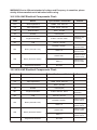
Electrical Components Chart:
WARNING:Due to different standard of voltage and Frequency in countries, please
strictly follow manufacturer’s indication before using.
Mark Name Specification and Model Remark
Crun
Cst
YC
QF
M1
M2
SB1
SB2
Work Capacitance
Start Capacitance
Solenoid Valve
Breaker
Single Phase Motor
FAN
Button (Automatic Lock)
Button (Automatic Retract)
Integrated Circuit Board
CBB60 70uF 300V.AC
CD60 300uF 150V.AC
GZ3-1 24V.DC
TRL32A(15A)
0.9KW 115V.AC 60HZ
110V.AC 23/21W
GQ25-11Z
GQ25-11
BY31002
Switch for hot
protecting
LAS2GQH-11Z/S/FP
GQ16H-10/S
Select for big
remote control
Select for big
remote control
Select for samll
remote control
Select for samll
remote control
Mark Name Specification and Model Remark
Crun
Cst
YC
QF
M1
M2
SB1
SB2
Work Capacitance
Start Capacitance
Solenoid Valve
Breaker
Single Phase Motor
FAN
Button (Automatic Lock)
Button (Automatic Retract)
Integrated Circuit Board
CBB60 30uF 450V.AC
CD60 150uF 250V.AC
GZ3-1 24V.DC
TRL32A(10A)
0.9KW 220V.AC 60HZ
220V.AC 23/21W
GQ25-11Z
GQ25-11
BY31002
Switch for hot
protecting
LAS2GQH-11Z/S/FP
GQ16H-10/S
Select for big
remote control
Select for big
remote control
Select for samll
remote control
Select for samll
remote control
200-240V 60HZ Electrical Components Chart:
11

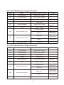
Mark Name Specification and Model Remark
Crun
Cst
YC
QF
M1
M2
SB1
SB2
Work Capacitance
Start Capacitance
Solenoid Valve
Breaker
Single Phase Motor
FAN
Button (Automatic Lock)
Button (Automatic Retract)
Integrated Circuit Board
CBB60 70uF 300V.AC
CD60 300uF 150V.AC
GZ3-1 24V.DC
TRL32A(15A)
0.9KW 115V.AC 50HZ
110V.AC 23/21W
GQ25-11Z
GQ25-11
BY31002
Switch for hot
protecting
LAS2GQH-11Z/S/FP
GQ16H-10/S
Select for big
remote control
Select for big
remote control
Select for samll
remote control
Select for samll
remote control
Mark Name Specification and Model Remark
Crun
Cst
YC
QF
M1
M2
SB1
SB2
Work Capacitance
Start Capacitance
Solenoid Valve
Breaker
Single Phase Motor
FAN
Button (Automatic Lock)
Button (Automatic Retract)
Integrated Circuit Board
CBB60 25uF 450V.AC
CD60 150uF 300V.AC
GZ3-1 24V.DC
TRL32A(10A)
1.1KW 220V.AC 50HZ
220V.AC 23/21W
GQ25-11Z
GQ25-11
BY31002
Switch for hot
protecting
LAS2GQH-11Z/S/FP
GQ16H-10/S
Select for big
remote control
Select for big
remote control
Select for samll
remote control
Select for samll
remote control
100-120V 50HZ Electrical Components Chart:
200-240V 50HZ Electrical Components Chart:
12

Specification & Parameter
13

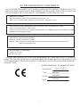
EC DECLARATION OF CONFORMITY
THIS IS HEREBY DECLARED THAT FOLLOWING DESIGNATED PRODUCT COMPLIED WITH THE
ESSENTIAL HEALTH AND SAFETY REQUIREMENTS OF MACHINERY DIRECTIVE 2006/42/EC ON
THE APPROXIMATION OF THE LAWS OF THE MEMBER STATES RELATING TO IT.
MANUFACTURER
Hangzhou WREN Hydraulic Equipment Manufacturing Co.,Ltd
ADD:No.24, Xingxing Road, xingqiao,yuhang district , Hangzhou, China
AU
THORIZED REPRESENTATIVE TO HOLD THE TECHNICAL FILES
Name of authorized person: Fritz Fischer
Address of authorized person: PETER ROSEGGERSTR.12, GERMANY 85293, REICHERTSHAUSEN
MAILBOX: hstfischer@t-online.de
DESCRIPTION OF MACHINERY
PRODUCT NAME: HYDRAULIC PUMP
MODEL TYPE:KLW4000 Series/KLW4100 Series/KLW4000N Series/ MP Series /SMP Series
/HNP Series/SHNP Series
APPLICABLE STANDARD
EN ISO 12100:2010
EN ISO 4413:2010
THIS DECLARATION APPLIES TO ALL SPECIMENS MANUFACTURED IDENTICAL TO THE MODEL
SUBMITTED FOR TESTING/EVALUATION.ASSESSMENT OF COMPLIANCE OF THE PRODUCT WITH
THE REQUIREMENTS RELATING TO SAFETY STANDARDS LISTED ABOVE WAS PERFORMED BY
MANUFACTURE.
SIGNED ON BEHALF OF MANUFACTURER
SIGNATURE:
TITLE:
PLACE:
DATE:
Manager
Hangzhou
2012/8/9
14

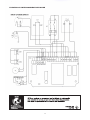
ELECTRICAL INTERCONNECTDE FIGURE
15

液压液 压泵的安 全使用, 必须要求 正确操作 和定期检 查。
在阅读 和彻底理 解本手册 中的安全 指示条例 后才可以 使用本液压泵。
注意事 项--防止造 成直接经 济损失或 财物损失 。
警告事 项--防止造 成人身伤 害。
请确实 遵守上述 两个事项 。
在使用 过程中, 如发生异 常情况, 请关闭电 源开关, 拨出电源插头,然后向WREN 或WREN授权
代理商 咨询。
安 全 指 示
本 操作手 册 内 容包括WREN液压 液 压泵的 操 作 规 程、警 告 和 注意事 项 以 及故障 排 除 。
使 用前,请仔细阅读本手册,彻底理解其内容并妥善保管。
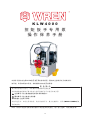
K L W 4 0 0 0
扭 矩 扳 手 专 用 泵
操 作 保 养 手 册
声 明:所 有 产 品图片 说 明 均有可 能 因 产品改 进 升 级而变 更 , 恕 不另行 通 知 ,均以 实 物 为准!
16

1. 使用本 液压泵时 ,所有人 员禁止站 在液压油 出口处, 防止液压油不小心泄漏时可能发生的人身伤
害或财 产损失; 液压泵必 须远离火 源。
2. 加压前 ,应加装 软管及执 行元件或 螺堵,防 止高压液 压油冲出造成人身伤害。
3. 本液压 液压泵的 最高工作 压力为70MPa;在出 厂时工厂 已设定压 力为70MPa, 绝不要将 压力调节
到超过 设定压力 。
4. 如本液 压泵用于 操作其它 配套设备 ,配套设 备的工作 压力应小于70MPa,并 将压力调定为其配套
设备的 工作压力 ,否则配 套设备有 可能损坏 ;调整压 力调节阀的操作参见第五项。
5. 充分考 虑安全性 ,在维修 前,应将 动力源切 断。
6. 在接通 动力源前 ,关掉按 钮开关,打开 液压调节 阀。
7. 确保接 地,避免 触电。
8. 禁止无 油启动液 压泵站, 这将会造 成设备损 坏。
9. 不要改 装本液压 泵,如确 实需要改 装,应先 向WREN 或WREN授 权代理商 咨询。没 有WREN的书
面同意 ,所作改 装,不在 质保范围 内。
10. 不要 加注超过 可用油量 的液压油 ,否则, 贮油箱 中的液压 油会溢出 , 造成对 环境和设 备污染。
11. 液压泵站 工作时, 返回储油 箱的油可 能会溢出 ,如果此 时打开储 油箱盖, 可能会造 成设备和 环境
的污染 。
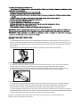
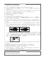
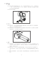
12. 快速 接头互连 时,必须 保证完全 啮合(图1) ,只有这 样才能确 保接头内 单向阀打开,使油路畅
通。否 则,连接 后接头内 单向阀无 法打开, 致使油路 不通,加压时会出现泵站有压力,而扳手无
法运转 、从扳手 旋转体上 的自动泻 荷阀打开,开 始泻压等 现象,从而可能造成快速接头、扳手损坏,
甚至人 身伤害。
此时须 切断液压 泵动力源 ,拆开所 有软管接 头,检查 所有快速接头(包括扳手接头)内的单
向阀是 否可以用 手按动、 有弹性。 如果不能 按动,需 要用锤子敲打接头内单向阀(图2),释放接
头里的 压力(敲 打单向阀 时会有液 压油喷出 ,虽没有 危险,但需小心液压油溅到身上,弄脏您的
衣服) ,直至用 手可以按 动接头内 钢珠为止 ,再重新 连接。
13. 必须 保持液压 泵站的清 洁,特别 是出油口 、快速接 头等处, 液压油的 不清洁是引发液压泵故障的
主要原 因。
14. 远离 超高压液 压油可能 溢出的位 置;液压 油可能穿 透你的手 ,导致严 重受伤。
15. 如果 液压油喷 到你的眼 睛里,立 即用清水 冲洗大约15分钟,然后去医院清洁眼睛。
16. 不要 碰带压力 的软管; 如果液压 油喷出, 会导致严 重伤害。
17. 液压 软管是消 耗性配件 ,经过肉 眼检查没 有问题, 内部也可 能有破裂 和针孔;考虑到良好使用
状况, 应定期更 换软管, 且使用时 应避免出 现急弯。
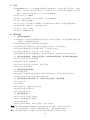
1. 只使用WREN液压工 具专用油 。
2. 使用过 的液压油 应根据防 污染条例 处理。
注 意 事 项
警 告 事 项
图(1)
图(2)
17

一 概述
为液压 扳手专用
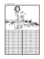
二 零部件概述及外观示意图
零部件 概述
( )
( )
1.1 KLW4000 泵,采 用集成方 式组装, 由动力单 元,电气单元,控 制装置等 组成的
一种独 立完整的 液压装置 ,具有流 量大、体 积小、重 量轻、结构简单、操作方便、工作压力
高等特 点,并且 高压出口 (A口)出油 压力可在70~700bar间任意调节。
#
1.2 液压 液压泵使 用的液压 油:32 耐磨液 压油。严 禁使用含 水和含对 钢或铝有 腐蚀性介 质的液压
油。
1.3 液压 液压泵使 用的环境 温度:-10~60℃(如更换低温液压油,可在-30℃ 低温下使 用)。
1.4 液压 液压泵通 过高压软 管和高压 接头与执 行元件连 接,为工 作安全, 请使用WREN高压软管
和高压 接头。WREN液压液压 泵配用的 高压软管 最大工作 压力为70MPa,使用 时请选用 与之
配套的 压力系统 。
1.5 此泵 如需使用 附属液压 产品,请 咨询WREN工程师。
1.6 请不 要在靠近 火焰处使 用液压液 压泵。
1.7 液压 液压泵的 最大工作 压力70MPa, 使用时请 不要任意 调节压力 调节阀, 以避免超 高压引起
的设备 损坏和人 身伤害。 (如有特 殊要求, 请咨询WREN工程师。)
1.8 请确 认WREN液压液压泵的使用电压与现场使用的电压相符。
1.9 请尽 可能在室 内使用此 泵,室外 使用必须 做好防雨 措施。
2.1
1 储油箱 :存放工 作用液压 油,保证 系统正常 工作(必 须有足够油量),提供系统所需的
压力载 体。
2 压力调 节阀(溢 流阀): 调节此阀 可以设定 液压泵的 工作压力,(出厂时已锁定最高工
作压力 ,禁止调 高锁定压 力)。
(3) 压力表 :显示液 压泵的工 作压力, 量程100 Mpa。
(4) 油泵保 护架:安 装在储油 箱上,用 于提携、 保护液压 泵站。
(5) 电机: 提供动力 源(根据 使用地的 电压、频 率选用合 适电机,具体参数见电机铭牌)。
(6) 冷却器 :实行强 制冷却, 降低油泵 工作时的 油温,从 而延长扳手工作时间和使用寿命。
(7) 液位计 :观察液 压油的多 少,以保 证提供最 佳使用油 量;液压油低于油标1/3位置时,
必须加WREN泵站专 用液压油 ,否则可 能会损坏 泵站。
(8) 卸油孔 :螺塞G1/4”,实现液压油排出储油箱 (更换液 压油时使 用)。
(9) 电控系 统:液压 泵的电气 控制部分 ,实现对 液压泵开 始打压、高低压转换和停止打压的
控制。
(10) 油箱盖:密封油箱及安装液压泵零部件。
(11) 换向阀:实现高、低压液压油输出、回油的换向功能。
(12) 快速接头:实现液压油输出\回油功能,快速 连接油管 ;含内置 式单向阀 ,凸凹接 头的螺
纹套拧 紧。齿部 卡住后在 升压、降 压、脉动 过程中不 会使螺纹套松开,具有防松功能。
(13) 阀组:连接液压系统中的各种液压控制阀 ,实现液 压油输出 、回油控 制,保证 系统在设
定压力 下正常工 作。
(14) 通气注油孔:储油箱换气和注入液压油的 通道。
18

装配示 意图2.2
序号 说明 序号 说明
1 储油箱 8 卸油孔
2 压力调节阀(溢流阀) 9 电控系统
3 压力表 10 油箱盖
4 油泵保护架 11 换向阀
5 电机 (参数见铭牌) 12 快速接头
6 冷却器 13 阀组
7 液位计 14 通气注油孔
19
ページが読み込まれています...
ページが読み込まれています...
ページが読み込まれています...
ページが読み込まれています...
ページが読み込まれています...
ページが読み込まれています...
ページが読み込まれています...
ページが読み込まれています...
ページが読み込まれています...
ページが読み込まれています...
ページが読み込まれています...
ページが読み込まれています...
-
 1
1
-
 2
2
-
 3
3
-
 4
4
-
 5
5
-
 6
6
-
 7
7
-
 8
8
-
 9
9
-
 10
10
-
 11
11
-
 12
12
-
 13
13
-
 14
14
-
 15
15
-
 16
16
-
 17
17
-
 18
18
-
 19
19
-
 20
20
-
 21
21
-
 22
22
-
 23
23
-
 24
24
-
 25
25
-
 26
26
-
 27
27
-
 28
28
-
 29
29
-
 30
30
-
 31
31
-
 32
32


Wren KLW4000D Operation and Maintenance Manual
- タイプ
- Operation and Maintenance Manual
他の言語で
- English: Wren KLW4000D
関連論文
その他のドキュメント
-
Sony XRM-55X90K Getting Started
-
-
-
Zebra SB1 取扱説明書
-
-
DURKOPP ADLER 251-140042 Manual Motor
-
Greenlee PVA0021, PVA0022 Hydraulic Control Valves-Chinese ユーザーマニュアル
-
-
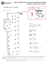 Bitspower BPTA-WDP570X-KIT インストールガイド
-
