Greenlee HB10 Dynapress Hydraulic Booster-Chinese ユーザーマニュアル
- タイプ
- ユーザーマニュアル

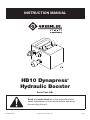
INSTRUCTION MANUAL
HB10 Dynapress
®
Hydraulic Booster
Read and understand all of the instructions and
safety information in this manual before operating
or servicing this unit.
52045407 REV 2 © 2012 Greenlee Textron Inc. 12/12
Serial Code GBL

HB10 Dynapress
®
Hydraulic Booster
Greenlee / A Textron Company 4455 Boeing Dr. • Rockford, IL 61109-2988 USA • 815-397-7070
2
Description
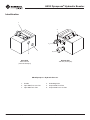
The Greenlee Utility HB10 Dynapress
®
Hydraulic
Booster is a piston-type accessory intended to allow the
use of a high pressure/low ow tool with a low pres-
sure/high ow hydraulic power source. Compatible with
either open-center or closed-center hydraulic systems,
the unit takes a hydraulic input of 69 to 152 bar (1000
to 2200 psi) and produces a stable output of 700 bar
(10,000 psi).
The HB10 can be installed in existing two-hose type
hydraulic systems, and does not require a third hydrau-
lic line or separate reservoir. The compact and light-
weight design allows the unit to be easily carried and
used on the ground or in an aerial lift basket. Actuating
the high-pressure circuit of the Dynapress
®
booster
requires a remote control valve, purchased separately.
The instructions and illustrations in this manual reect
using the HB10 with either of the following Greenlee
Utility remote control valves:
• PVA0021A Single-Acting Control Valve
• PVA0022A Double-Acting Control Valve
The terms “unit” and “booster,” when used in this
manual, refer to the HB10. The term “tool” refers to the
device (cable cutter, crimping tool, etc) that is powered
by the HB10.
Safety
Safety is essential in the use and maintenance of
Greenlee Utility tools and equipment. This instruction
manual and any markings on the unit provide informa-
tion for avoiding hazards and unsafe practices related to
the use of this unit. Observe all of the safety information
provided.
Purpose of this Manual
This instruction manual is intended to familiarize
all personnel with the safe operation and maintenance
procedures for the Greenlee Utility HB10 Dynapress
®
Hydraulic Booster.
Keep this manual available to all personnel.
Replacement manuals are available upon request at no
charge.
All specications are nominal and may change as design
improvements occur. Greenlee Textron Inc. shall not be liable for
damages resulting from misapplication or misuse of its products.
Dynapress is a registered trademark of Greenlee Textron Inc.
KEEP THIS MANUAL
Table of Contents
Description .................................................................... 2
Safety ............................................................................ 2
Purpose of this Manual ................................................. 2
Important Safety Information .....................................3–4
Identication .................................................................. 5
Specications ................................................................ 6
Hose Connections ......................................................... 7
Typical Setup ................................................................. 7
Operation ....................................................................... 8
Maintenance .................................................................. 9
Troubleshooting ........................................................... 10
Illustration and Parts List ........................................11–12
Accessories ................................................................. 13
Hose and Hose Assemblies (SAE J1273) ............... 14–15

HB10 Dynapress
®
Hydraulic Booster
Greenlee / A Textron Company 4455 Boeing Dr. • Rockford, IL 61109-2988 USA • 815-397-7070
3
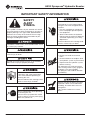
IMPORTANT SAFETY INFORMATION
SAFETY
ALERT
SYMBOL
This symbol is used to call your attention to hazards
or unsafe practices which could result in an injury or
property damage. The signal word, dened below,
indicates the severity of the hazard. The message
after the signal word provides information for pre-
venting or avoiding the hazard.
Immediate hazards which, if not avoided, WILL result
in severe injury or death.
Hazards which, if not avoided, COULD result in
severe injury or death.
Hazards or unsafe practices which, if not avoided,
MAY result in injury or property damage.
Read and understand all of the
instructions and safety information
in this manual before operating or
servicing this unit.
Failure to observe this warning could
result in severe injury or death.
Wear eye protection when operating
or servicing this unit.
Failure to wear eye protection could
result in serious eye injury from ying
debris or hydraulic oil.
Electric shock hazard:
This booster is not insulated. When
using this unit near energized electri-
cal lines:
• Use only certied non-conductive
hoses and proper personal protec-
tive equipment.
• Select and maintain the hydraulic
uid to meet the minimum dielectric
standards required by your safety
department.
Failure to observe this warning could
result in severe injury or death.
Skin injection hazard:
• Do not use hands to check for
leaks.
• Do not hold hose or couplers while
the hydraulic system is pressurized.
• Depressurize the hydraulic system
before servicing.
Oil under pressure easily punctures
skin causing serious injury, gangrene
or death. If you are injured by
escaping oil, seek medical attention
immediately.
Booster may be hot during and after
operation. Allow unit to cool before
handling, or handle with heat-resis-
tant gloves.
Hot surfaces could cause severe
burns.

HB10 Dynapress
®
Hydraulic Booster
Greenlee / A Textron Company 4455 Boeing Dr. • Rockford, IL 61109-2988 USA • 815-397-7070
4
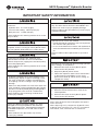
IMPORTANT SAFETY INFORMATION
Do not exceed the following hydraulic power source
maximums:
• Hydraulic ow: 30.3 l/min (8 gpm)
• Pressure relief setting: 148 bar (2150 psi)
• Back pressure: 13.8 bar (200 psi)
Failure to observe this warning could result in severe
injury or death.
Do not disconnect booster, hoses, or ttings while
the power source is running or if the hydraulic uid is
hot. Hot hydraulic uid could cause serious burns.
Do not reverse hydraulic ow. Operation with
hydraulic ow reversed can cause a malfunction.
Connect the pressure (supply) hose and tank (return)
hose to the proper ports.
Failure to observe this warning could result in severe
injury or death.
• Inspect the hydraulic hoses and couplings every
operating day. Repair or replace if leakage, crack-
ing, wear, or damage is evident. Damaged hoses
or couplings can fail, resulting in injury or property
damage.
• Make sure all bystanders are clear of the work area
when handling, starting and operating tool. Nearby
personnel can be injured by ying or falling debris
or by ying parts in the event of a malfunction.
Failure to observe these warnings could result in
severe injury or death.
Inspect unit before operating. Replace any worn,
damaged or missing components with Greenlee
Utility replacement parts. A damaged or improperly
assembled component can fail and strike nearby
personnel.
Failure to observe this precaution may result in
severe injury or death.
Use this unit for manufacturer’s intended purpose
only. Use other than that which is described in this
manual can result in injury or property damage.
Failure to observe this precaution may result in injury
or property damage.
Hydraulic oil can cause skin irritation.
• Handle the booster and hoses with care to prevent
skin contact with hydraulic oil.
• In case of accidental skin contact with hydraulic oil,
wash the affected area immediately to remove the
oil.
Failure to observe these precautions may result in
injury.
Procedure for connecting or disconnecting hydraulic
hoses, ttings, or components:
1. Move the ow lever on the hydraulic power
source to the OFF position.
2. Stop the hydraulic power source.
3. Follow the sequence under “Hose Connections”
to prevent pressure buildup. In case some
pressure has built up, loosen hoses, ttings, or
components slowly.
Emergency stop procedure:
1. Move the remote control valve’s lever to the
neutral position.
2. Move the ow lever on the hydraulic power
source to the OFF position.
Note: Keep all decals clean and legible, and replace
when necessary.
When disposing of any components (hydraulic hoses,
hydraulic fluid, worn parts, etc.), do so in accordance
with federal, state, and local laws or ordinances.

HB10 Dynapress
®
Hydraulic Booster
Greenlee / A Textron Company 4455 Boeing Dr. • Rockford, IL 61109-2988 USA • 815-397-7070
5
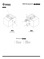
Identification
Input Side
69 to 152 bar
(1000 to 2200 psi)
Output Side
700 bar (10,000 psi)
HB10 Dynapress
®
Hydraulic Booster
1. Handle
2. Input Side Pressure Port
3. Input Side Tank Port
4. Unloading Valve
5. Output Side Tank Port
6. Output Side Pressure Port
1
2
3
4
5
6

HB10 Dynapress
®
Hydraulic Booster
Greenlee / A Textron Company 4455 Boeing Dr. • Rockford, IL 61109-2988 USA • 815-397-7070
6
Specifications
HB10
Type of Hydraulic System .............................Open-center
or closed-center
Hydraulic Ports and Couplers
Power Source (low pressure) Ports
Pressure ............................ 3/4–16 SAE O-ring Boss
Tank .................................. 3/4–16 SAE O-ring Boss
Tool (high pressure) Couplers
Pressure .................. 1/4–18 NPTF (Parker #3050-2)
Tank ........................ 1/4–18 NPTF (Parker #3010-2)
Input Pressure ...............69 to 152 bar (1000 to 2200 psi)
Output Pressure ............................... 700 bar (10,000 psi)
Noise Level (at operator’s position) ................ < 85 dB (A)
Mass/Weight ............................................. 4.7 kg (10.3 lb)
Width
Housing Only ............................................. 102 mm (4")
Housing and Couplers .........................159 mm (6.25")
Height (handle folded) ................................114 mm (4.5")
Hydraulic Power Source
Do not exceed the following hydraulic power source
maximums:
• Hydraulic ow: 30.3 l/min (8 gpm)
• Pressure relief setting: 148 bar (2150 psi)
• Back pressure: 13.8 bar (200 psi)
Failure to observe this warning could result in severe
injury or death.
Type of Hydraulic System .............................Open-center
or closed-center
Flow
Minimum ......................................... 15.1 l/min (4 gpm)
Recommended ................................ 22.7 l/min (6 gpm)
Maximum ........................................ 30.3 l/min (8 gpm)
Pressure Relief Setting ........................ 148 bar (2150 psi)
Back Pressure (maximum)* .................. 13.8 bar (200 psi)
Filtration .............................................10 Micron (nominal)
* 13.8 bar (200 psi) is the maximum agreed standard back pressure
for the HTMA (Hydraulic Tool Manufacturers Association).
Greenlee Utility tool will operate satisfactorily at this standard.
1. Maximum hydraulic uid temperature must not
exceed 60 °C (140 °F). A sufcient oil cooling
capacity is needed to limit the hydraulic uid
temperature.
2. Hydraulic ow must not exceed 30.3 l/min (8 gpm).
Install a ow meter in the return line to measure to
rate of hydraulic ow before using the unit.
3. Pressure relief valve setting must not exceed
148 bar (2150 psi) at your tool’s maximum ow.
Locate the pressure relief valve in the supply circuit
to limit excessive hydraulic pressure to the booster.
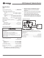
Hydraulic Schematic
FILTER
(10 MICRON)
COOLER
RELIEF
VALVE
138 bar
(2000 psi)
CONTROL
VALVE
FLOW METER
T
P
TOOL
RESERVOIR
PUMP
POWER SOURCE
Recommended Hydraulic Fluids
Use any non-detergent, petroleum-based hydraulic
uid which meets the following specications or HTMA
specications.
S.U.S. @
38 °C (100 °F) .............................................. 140 to 225
99 °C (210 °F) ........................................... 40 minimum
Flash Point ................................ 170 °C (340 °F) minimum
Pour Point .................................. -34 °C (-30 °F) minimum

HB10 Dynapress
®
Hydraulic Booster
Greenlee / A Textron Company 4455 Boeing Dr. • Rockford, IL 61109-2988 USA • 815-397-7070
7
Hose Connections
Connecting Hoses
Use this procedure to prevent pressure buildup in the
hydraulic circuit:
1. Move the ow lever on the hydraulic power source
to the OFF position.
2. Stop the hydraulic power source.
3. Connect high-pressure hoses to the high-pressure
ports as follows:
• return (tank) hose: remote control valve to
booster
• supply (pressure) hose: remote control valve to
booster
• return (tank): remote control valve to tool
(This step applies to double-acting tool and
control valve only.)
• supply (pressure) hose: remote control valve to
tool
4. Connect the low-pressure hoses to the low-pressure
ports as follows:
• return (tank) hose: booster to power source
• supply (pressure) hose: power source to booster
Disconnecting Hoses
Use this procedure to prevent pressure buildup in the
hydraulic circuit:
1. Move the ow lever on the hydraulic power source
to the OFF position.
2. Stop the hydraulic power source.
3. Disconnect the hoses in reverse order of the con-
nection sequence.
4. Install dust caps to prevent contamination.
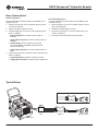
Typical Setup
HB10 PVA0021A
Optional: Tool connected to control valve
Single-acting Tool
Power Source

HB10 Dynapress
®
Hydraulic Booster
Greenlee / A Textron Company 4455 Boeing Dr. • Rockford, IL 61109-2988 USA • 815-397-7070
8
Operation
Electric shock hazard:
This booster is not insulated. When
using this unit near energized electri-
cal lines:
• Use only certied non-conductive
hoses and proper personal protec-
tive equipment.
• Select and maintain the hydraulic
uid to meet the minimum dielectric
standards required by your safety
department.
Failure to observe this warning could
result in severe injury or death.
Skin injection hazard:
• Do not use hands to check for
leaks.
• Do not hold hose or couplers while
the hydraulic system is pressurized.
• Depressurize the hydraulic system
before servicing.
Oil under pressure easily punctures
skin causing serious injury, gangrene
or death. If you are injured by
escaping oil, seek medical attention
immediately.
Wear eye protection when operating
or servicing this unit.
Failure to wear eye protection could
result in serious eye injury from ying
debris or hydraulic oil.
Read and understand all of the instructions and
safety information supplied with the tool.
Failure to observe this warning could result in severe
injury or death.
1. Start the hydraulic power source.
Note: Allow the power source to run for a few
minutes to warm the hydraulic fluid.
2. To actuate the tool, press down and hold the lever in
the ADVANCE position.
• When the pressure exceeds approximately
207bar (3000 psi), the operator may release the
control lever. The lever will remain in the
ADVANCE position.
• When the pressure reaches the relief setting of
the unloading valve – 700 bar (10,000 psi) – the
high pressure oil will dump back to tank and the
system pressure will drop to nearly zero. The
operator can then release the remote control lever
back to the neutral position.
3. To return or retract the ram, press down and hold
the lever in the RETRACT position.

HB10 Dynapress
®
Hydraulic Booster
Greenlee / A Textron Company 4455 Boeing Dr. • Rockford, IL 61109-2988 USA • 815-397-7070
9
Maintenance
Skin injection hazard:
• Do not use hands to check for
leaks.
• Do not hold hose or couplers while
the hydraulic system is pressurized.
• Depressurize the hydraulic system
before servicing.
Oil under pressure easily punctures
skin causing serious injury, gangrene
or death. If you are injured by
escaping oil, seek medical attention
immediately.
Wear eye protection when operating
or servicing this unit.
Failure to wear eye protection could
result in serious eye injury from ying
debris or hydraulic oil.
Note: Keep all decals clean and legible, and replace
when necessary.
When disposing of any components (hydraulic hoses,
hydraulic fluid, worn parts, etc.), do so in accordance
with federal, state, and local laws or ordinances.
Daily
1. Wipe all booster surfaces clean.
2. Inspect the hydraulic hoses and ttings for signs
of leaks, cracks, wear or damage. Replace if
necessary.
3. Install dust caps when the unit is disconnected.
Monthly
Perform a thorough inspection of the hydraulic
hoses and ttings as described in “Hose and Hose
Assemblies” at the end of this manual or in publication
99930323, SAE J1273.
Periodically
Use a non-lled pressure gauge, like the Greenlee
Utility 137779, to verify that the unloading valve relief
pressure
is 700 bar (10,000 psi). Send the booster to a
Greenlee Utility Authorized Service Center if adjustment
is necessary.
Annually
If required by your organization, have the booster
inspected by a Greenlee Utility Authorized Service
Center.

HB10 Dynapress
®
Hydraulic Booster
Greenlee / A Textron Company 4455 Boeing Dr. • Rockford, IL 61109-2988 USA • 815-397-7070
10
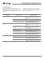
Problem Probable Cause Probable Remedy
Booster does not operate.
Improper power source. Verify that the power source meets the
specications. Refer to the “ Specications”
section.
Hydraulic uid level low. Check the uid level. Check system for leaks.
Incorrect hydraulic uid viscosity. Use hydraulic uid with the correct viscosity.
Refer to the “Specications” section.
Booster operates slowly or
erratically.
Hydraulic uid cold. Allow uid to warm to the operating
temperature.
Actuate the tool intermittently
to reduce the
warming time.
Power source not adjusted
correctly.
Refer to power source operator’s manual.
Set the ow and pressure to correspond
with the booster.
Hydraulic uid level low. Check the uid level. Check system for leaks.
Air in the hydraulic system.
Refer to power source manufacturer’s
instructions for removing air from the system.
Incorrect hydraulic uid viscosity. Use hydraulic uid with the correct viscosity.
Refer to the “Specications” section.
Tool feels hot.
Hydraulic uid level low. Check the uid level. Check system for leaks.
Incorrect hydraulic uid viscosity. Use hydraulic uid with the correct viscosity.
Refer to the “Specications” section.
Hydraulic uid dirty. Refer to the power source owner’s manual for
procedure to replace hydraulic oil and lter.
Troubleshooting
Before troubleshooting, determine whether the problem
is in the booster, the hoses, or the power source.
Substitute a booster, hoses, or power source known to
be in good working order to identify the item that is not
operating.
If the problem is in the booster, refer to the trouble-
shooting table below. If the problem is in the power
source, refer to the troubleshooting section of the power
source instruction manual.

HB10 Dynapress
®
Hydraulic Booster
Greenlee / A Textron Company 4455 Boeing Dr. • Rockford, IL 61109-2988 USA • 815-397-7070
11
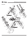
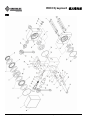
Illustration
1
34
52
11
8
49
24
4
40*
50
40*
21
23*
22
18
10
37
27
25*
30
33
29
31
28
54
53
32*
55*
39
9
14*
12*
16
47*
50
13
38
48*
48*
3
2
16
51*
50
26
35
36
42
41
44
5
45
46*
6
8
19
7
56

HB10 Dynapress
®
Hydraulic Booster
Greenlee / A Textron Company 4455 Boeing Dr. • Rockford, IL 61109-2988 USA • 815-397-7070
12
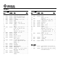
Parts List
1 76834 52001736 Housing, wobble plate ............................1
2 20967 52024955 Housing assembly, motor Gerotor ..........1
3 10376 52024956 Housing assembly,
scavenger Gerotor .................................1
4 49834 50498347 Housing, high pressure ...........................1
5 49835 52001738 Screw, cap, 5/16–18 x 4.5, skt hd ..........6
6 13144 52001038 Plate, wobble ..........................................1
7 13131 52001039 Washer, thrust 1.785 I.D. ........................2
8 41892 50418921 Bearing, thrust 1.750 x 2.500 x .078 ......2
†9 Bushing, piston ......................................2
†10 Piston ......................................................2
11 41895 50418951 Washer, thrust, 1.750 x 2.500 x .032 ......2
*†12 O-ring, .375 x .500 x .062–90D ..............2
†13 Ball, .125 diameter, steel ........................4
*†14 Back-up ring, single turn,
.390 x .4 92 x .048 ...................................2
16 43097 50430971 Bearing, needle, .750 x 1.500 .................3
18 49841 52001743 Shaft, drive .............................................1
19 13143 52001037 Retainer, bearing .....................................1
21 43120 50431200 Pin, dowel, .125 x .875 ...........................1
22 43149 50431498 Pin, dowel, .187 x 1 ................................1
*23 Ball, .187 diameter, steel ........................1
24 41888 50418881 Plug, pipe, 1/16 NPTF level seal.............1
*25 O-ring, .750 x .875 x .062–70D ..............1
26 Washer, lock, 5/16 ..................................6
27 40675 50406751 Cap, relief valve ......................................1
28 43961 50439618 Body, valve unloading ............................1
29 43930 50439308 Pintal, valve unloading ............................1
30 40682 50406821 Retainer, spring cup ................................1
31 41874 50418740 Screw, set, #8–32 x .109 hollow skt .......2
*32 Washer, at, .440 x .680 x .060,
copper ....................................................1
33 40692 50406921 Spring, unloading valve ..........................1
34 49960 52001744 Decal .......................................................1
35 Handle ....................................................1
36 Screw, cap #8 –32 x .375,
button head ............................................4
37 41834 50418341 Dust cap .................................................1
†38 Pin, dowel 1/16 x 7/16 ............................2
39 42096 50420961 Coupler, hydraulic ...................................1
*40 O-ring, .812 x 1.062 x .125–85D ............2
41 41344 50413442 Nipple, pipe 1/4 NPTF x 1.37 hex .........1
42 54169 51541690 Coupler, hydraulic ...................................1
43 41432 50414323 Plug, plastic 3/4 –16 ..............................2
44 41873 50418730 Ball, .500 diameter, steel ........................1
45 49234 50492349 Stop, ball ................................................1
*46 Ring, retaining, .687 Truarc .....................1
†47 Washer, at, .250 x .437 x .031,
copper ....................................................2
*48 O-ring, 2.500 x 2.625 x .062–70D ..........2
49 Screw, set, 1/4 –20 x .250 socket
head cup point .......................................1
50 40742 50407422 Pin, dowel, .188 x .500 ...........................6
*51 O-ring, .187 x .312 x .062–90D ..............1
*52 O-ring .....................................................1
53 40696 50406960 Retainer, check valve ..............................1
54 40697 50406970 Body, check valve ...................................1
*55 O-ring, .625 x .812 x .094–90D ..............1
56 41830 50418301 Dust cap .................................................1
Repair Kits
* 49979 50499793 Packing kit (includes items marked
with an asterisk) ......................................1
† 49980 50499807 Piston/bushing assembly (includes
items marked with †) ..............................1
UPC No.
Key 78-3310- Part No. Description Qty
UPC No.
Key 78-3310- Part No. Description Qty

HB10 Dynapress
®
Hydraulic Booster
Greenlee / A Textron Company 4455 Boeing Dr. • Rockford, IL 61109-2988 USA • 815-397-7070
13
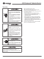
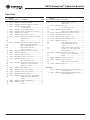
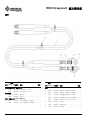
Accessories
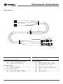
Complete Hose Assemblies Rated at 700 bar (10,000 psi)
41107 50411074 6 ft (includes items 1–7) ..........................1
41108 50411083 10 ft (includes items 1–7) ........................1
Remote Control Valves
42948 50429481 Single-acting ..........................................1
42949 50429491 Double-acting .........................................1
Hoses Rated at 700 bar (10,000 psi)
1 41795 50417951 6 ft, 1/4 MNPT x 1/4 MNPT ....................1
1 41796 50417961 10 ft, 1/4 MNPT x 1/4 MNPT ..................1
Couplers and Fittings
2 41401 50414014 Coupler, 1/4 FNPT x 1/4 FNPT ...............2
3 41344 50413442 Adapter, 1/4 MNPT x 1/4 MNPT .............1
4 54169 51541690 Male coupler, 1/4 FNPT ..........................1
5 42096 50420961 Female coupler, 1/4 MPNT .....................1
41842 50418421 O-ring, 5/8 x 13/16 x 3/32–90D ..........1
6 41834 50418341 Dust cap .................................................1
7 41587 50415870 Ty-Rap ....................................................3
8 41830 50418301 Dust cap .................................................1
UPC No.
Key 78-3310- Part No. Description Qty
UPC No.
Key 78-3310- Part No. Description Qty
5 6
2 3 4 8
7
1

HB10 Dynapress
®
Hydraulic Booster
Greenlee / A Textron Company 4455 Boeing Dr. • Rockford, IL 61109-2988 USA • 815-397-7070
14
SELECTION, INSTALLATION AND MAINTENANCE
OFHOSE AND HOSE ASSEMBLIES
—SAE J1273 1986
SAE Recommended Practice
1. Scope
Hose (also includes hose assemblies) has a nite
life and there are a number of factors which will reduce
its life.
This recommended practice is intended as a guide to
assist system designers and/or users in the selection,
installation, and maintenance of hose. The designers
and users must make a systematic review of each appli-
cation and then select, install, and maintain the hose to
fulll the requirements of the application. The following
are general guidelines and are not necessarily a com-
plete list.
Improper selection, installation, or maintenance may
result in premature failures, bodily injury, or property
damage.
2. Selection
The following is a list of factors which must be consid-
ered before nal hose selection can be made.
2.1 Pressure – After determining the system pressure,
hose selection must be made so that the recom-
mended maximum operating pressure is equal to
or greater than the system pressure. Surge pres-
sures higher than the maximum operating pres-
sure will shorten hose life and must be taken into
account by the hydraulic designer.
2.2 Suction – Hoses used for suction applications
must be selected to insure the hose will withstand
the negative pressure of the system.
2.3 Temperature – Care must be taken to insure that
uid and ambient temperatures, both static and
transient, do not exceed the limitations of the
hose. Special care must be taken when routing
near hot manifolds.
2.4 Fluid Compatibility – Hose selection must assure
compatibility of the hose tube, cover, and t-
tings with uid used. Additional caution must
be observed in hose selection for gaseous
applications.
2.5 Size – Transmission of power by means of pressur-
ized uid varies with pressure and rate of ow. The
size of the components must be adequate to keep
pressure losses to a minimum and avoid damage
to the hose due to heat generation or excessive
turbulence.
2.6 Routing – Attention must be given to optimum
routing to minimize inherent problems.
2.7 Environment – Care must be taken to insure that
the hose and ttings are either compatible with or
protected from the environment to which they are
exposed. Environmental conditions such as ultra-
violet light, ozone, salt water, chemicals, and air
pollutants can cause degradation and premature
failure and, therefore, must be considered.
2.8 Mechanical Loads – External forces can signi-
cantly reduce hose life. Mechanical loads which
must be considered include excessive exing,
twist, kinking, tensile or side loads, bend radius,
and vibration. Use of swivel type ttings or adapt-
ers may be required to insure no twist is put in the
hose. Unusual applications may require special
testing prior to hose selection.
2.9 Abrasion – While a hose is designed with a rea-
sonable level of abrasion resistance, care must be
taken to protect the hose from excessive abrasion
which can result in erosion, snagging and cutting
of the hose cover. Exposure of the reinforcement
will signicantly accelerate hose failure.
2.10
Proper End Fitting – Care must be taken to insure
proper compatibility exists between the hose and
coupling selected based on the manufacturer’s
recommendations substantiated by testing to
industry standards such as SAE J517d.
2.11
Length – When establishing proper hose length,
motion absorption, hose length changes due to
pressure, as well as hose and machine tolerances
must be con sidered.
2.12
Specications and Standards – When selecting
hose, government, industry, and manufacturer’s
specications and recommendations must be
reviewed and applicable.
2.13
Hose Cleanliness – Hose components vary in
cleanliness levels. Care must be taken to insure
that the assemblies selected have an adequate
level of cleanliness for the application.
2.14
Electrical Conductivity – Certain applications
require that the hose be non-conductive to prevent
electrical current ow. Other applications require
the hose to be sufciently conductive to drain off
static electricity. Hose and ttings must be chosen
with these needs in mind.
HOSE AND HOSE ASSEMBLIES

HB10 Dynapress
®
Hydraulic Booster
Greenlee / A Textron Company 4455 Boeing Dr. • Rockford, IL 61109-2988 USA • 815-397-7070
15
3. Installation
After selection of proper hose, the following factors
must be considered by the installer.
3.1 Pre-Installation Inspection – Prior to installa-
tion, a careful examination of the hose must be
performed. All components must be checked for
correct style, size, and length. In addition, the hose
must be examined for cleanliness, I.D. obstruc-
tions, blisters, loose cover, or any other visual
defects.
3.2 Follow Manufacturers’ Assembly Instructions.
3.3 Minimum Bend Radius – Installation at less than
minimum bend radius may signicantly reduce
hose life. Particular attention must be given to pre-
clude sharp bending at the hose/tting juncture.
3.4 Twist Angle and Orientation – Hose installations
must be such that relative motion of machine com-
ponents produces bending of the hose rather than
twisting.
3.5 Securement – In many applications, it may be
necessary to restrain, protect, or guide the hose
to protect it from damage by unnecessary exing,
pressure surges, and contact with other mechani-
cal components. Care must be taken to insure
such restraints do not produce additional stress or
wear points.
3.6 Proper Condition of Ports – Proper physical instal-
lation of the hose requires a correctly installed port
connection while insuring that no twist or torque is
put into the hose.
3.7 Avoid External Damage – Proper installation is
not complete without insuring tensile loads, side
loads, kinking, attening, potential abrasion, thread
damage, or damage to sealing surfaces are cor-
rected or eliminated.
3.8 System Check Out – After completing the installa-
tion, all air entrapment must be eliminated and the
system pressurized to the maximum system pres-
sure and checked for proper function and freedom
from leaks.
Note: Avoid potential hazardous area while testing.
4. Maintenance
Even with proper selection and installation, hose life
may be signicantly reduced without a continuing main-
tenance program. Frequency should be determined by
the severity of the application and risk potential.
A maintenance program should include the following as
a minimum.
4.1 Hose Storage – Hose products in storage can
be affected adversely by temperature, humidity,
ozone, sunlight, oils, solvents, corrosive liquids
and fumes, insects, rodents and radioactive mate-
rial. Storage areas should be relatively cool and
dark, and free of dust, dirt, dampness and mildew.
4.2 Visual Inspection – Any of the following conditions
requires replacement of the hose:
a. Leaks at tting or in hose.
(Leaking uid is a re hazard).
b. Damaged, cut or abraded cover.
(Any reinforcement exposed).
c. Kinked, crushed, attened or twisted hose.
d. Hard, stiff, heat cracked or charred hose.
e. Blistered, soft degraded or loose cover.
f. Cracked, damaged, or badly corroded ttings.
g. Fitting Slippage on hose.
4.3 Visual Inspection – The following items must be
tightened, repaired, or replaced as required:
a. Leaking port conditions.
b. Clamps, guards, shields.
c. Remove excessive dirt buildup.
d. System uid level, uid type, and any air
entrapment.
4.4 Functional Test – Operate the system at maximum
operating pressure and check for possible mal-
functions and freedom from leaks.
Note: Avoid potential hazardous areas
while testing.
4.5 Replacement Intervals – Specic replacement
intervals must be considered based on previous
service life, government or industry recommenda-
tions, or when failures could result in unacceptable
down time, damage, or injury risk.
Reprinted with permission from the 1990 SAE Handbook.
HOSE AND HOSE ASSEMBLIES (cont’d)

USA 800-435-0786 Fax: 800-451-2632
815-397-7070 Fax: 815-397-1865
Canada 800-435-0786 Fax: 800-524-2853
International +1-815-397-7070 Fax: +1-815-397-9247
4455 Boeing Drive • Rockford, IL 61109-2988 • USA • 815-397-7070
An ISO 9001 Company • Greenlee Textron Inc. is a subsidiary of Textron Inc.
www.greenlee.com

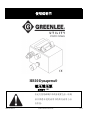
HB10 Dynapress®
液压增压泵
系列编号 GBL
52045407 REV 2 © 2012 Greenlee Textron Inc. 12/12
使用说明书
在运行使用或维护本设备装置之前,请阅
读并熟悉本使用说明书的所有说明与安
全信息。

Greenlee / A Textron Company 2 4455 Boeing Dr. • Rockford, IL 61109-2988 USA • 815-397-7070
HB10 Dynapress® 液压增压泵
目录
说明 .............................................................................. 2
安全 .............................................................................. 2
本使用说明书要旨 ...................................................... 2
主要安全信息 ........................................................ 3–4
部件标识 ...................................................................... 5
规格 .............................................................................. 6
油管连接 ...................................................................... 7
典型设置 ...................................................................... 7
操作 .............................................................................. 8
维护 .............................................................................. 9
故障排除 ...................................................................... 10
示意图与零件列表 ............................................. .11–12
配件 .............................................................................. 13
油管与油管总成 (SAE J1273) ............................ 14–15
本使用说明书中给出的规格均为标准标称的规格,可
随设计的改进予以更改。 Greenlee Textron 公司对误
用、错用本其产品而引起的任何损失、损害不负任何
责任。
Dynapress 为 Greenlee Textron 公司的一个注册商标。
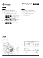
说明
Greenlee utility HB10 Dynapress®液压增压泵是活塞
型附件,其允许高压/低流量工具配置接到低压/高流
量液压源上使用。 该设备兼容开中位式或闭中位式液
压系统,该设备液压输入压力为 69-152bar
(1000-2200psi),稳定输出压力为 700bar(10000psi)。
HB 10 可安装在现有双油管型液压系统,无需第三方
液压管线或单独油箱(贮液器)。 小型、质轻设计使
该设备携带方便,可置于地面或空中升降斗中作业。
启动 Dynapress®增压泵高压回路需要一个远程控制
阀,该阀需另购置。 本手册中的说明和插图描述的情
况是 HB10 与下列 Greenlee utility 远程控制阀之一进
行配用:
• PVA0021A 单作用控制阀
• PVA0022A 双作用控制阀
本手册使用的术语“装置(unit)”和“增 压泵 ( booster)”,
均指 HB10。 术语“工具(tool)” 指 HB10 驱动的设
备(电缆剪、压接工具等)。
安全
在 Greenlee utility 工具和仪器设备的使用和维护过程
中,安全性是至关重要的一个因素。 该使用说明书以
及装置上的标记提供用以避免与本工具装置的使用有
关的危险和不安全做法的信息。 请遵守提供的所有安
全信息。
本使用说明书要旨
该使用说明书目的在于使所有人员熟悉 Greenlee
utility HB10 Dynapress® 液压增压泵的安全操作与维
护程序。
保证对所有人员提供本使用说明书,使之随时可资利
用。
如有要求,将免费提供本使用说明书手册的更换手册。
保留本使用说明书

Greenlee / A Textron Company 3 4455 Boeing Dr. • Rockford, IL 61109-2988 USA • 815-397-7070
HB10 Dynapress® 液压增压泵
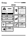
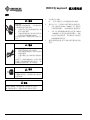
重要安全信息
安全警示符号
本符号用于提醒您注意,任何危险或不安全操作可能会
带来人身伤害或财产损失。 将通过定义如下的文字符
号描述危险的严重程度。 文字符号后面的信息则是用
以防止或避免危险的发生。
如果不加以防范,瞬时危险将导致严重的人员伤亡。
如果不加以防范,此危险可能导致严重的人员伤亡。
如果不加以防范,危险或不安全操作可能导致人身伤害
或财产损失。
警告
在运行使用或维护本装置之前,请
阅读并熟悉理解本使用说明书的所
有说明与安全信息。
如不遵守本警告,将可能会导致严
重的人员伤亡。
警告
在操作使用或维护该装置时配戴眼
罩。
不遵循本规定佩戴护眼罩的,飞屑
或液压油可能会严重伤害眼部。
警告
触电危险:
该增压泵为非绝缘装置设备。 当在
通电的电力管线附近使用该装置
时:
应仅使用已鉴定的绝缘油管和
正确的个人防护设备。
应选择和维护液压流体以符合
您的安全部门要求的最低电介
质标准。
如不遵守本警告,将可能会导致严
重的人员伤亡。
警告
皮肤受喷射危险:
请勿用手检查是否存在泄露。
液压系统加压的时候,请勿手
持油管或连接装置。
在进行维护之前,降低液压系
统的压力。
油受压后,很容易刺破皮肤,从而
严重伤害皮肤,导致皮肤组织坏死
甚至死亡。 如果你被流出的油所
伤,请立即就医。
警告
增压泵在操作中和操作后可能很
热。 装置冷却后进行操作处理,或
戴上隔热手套进行操作。
热表面会可能导致严重烫伤。
危险
警告
小心

Greenlee / A Textron Company 4 4455 Boeing Dr. • Rockford, IL 61109-2988 USA • 815-397-7070
HB10 Dynapress® 液压增压泵
重要安全信息
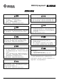
警告
勿超过下列液压动力源最大值:
液压流量: 30.3 l/min (8 gpm)
压力释放设置: 148 bar (2150 psi)
背压: 13.8 bar (200 psi)
如不遵守本警告,可能会导致严重的人员伤亡。
警告
当液压动力源在运转中或液压流体很热时,勿断开增压
泵、油管或接头。 热液压流体可能会导致严重烫伤。
警告
勿倒转液压流向。 液压流反向运行可能会导致故障。 将
压力(供压)管和油箱(回流)油管连接至正确接口。
如不遵守本警告,可能会导致严重的人员伤亡。
警告
每个工作日须检查液压油管和偶联器。 若出现泄
露、破裂、磨损或损坏,应进行修理或更换。 受损
油管或偶联器可能会失效,从而带来人身伤害或财
产损失。
处置、启动和使用工具时,确保所有旁观者处于工
作区域之外。 如果出现故障。附近人员可能受到飞
溅或掉落的碎片或飞溅的零件所伤害。
如不遵守本警告,可能会导致严重的人员伤亡。
小心
操作前检查装置。
采用
Greenlee utility
替换零件更换已
磨损、损坏或缺失的部件。 损坏的或组装不当的组件可
能会失效从而伤害到附近人员。
如不遵守本警告,可能会导致严重的人员伤亡。
小心
仅允许将本装置用于实现制造商规定的目的。 使用情况
与本说明书中所述不同可能导致人身伤害或财产损失。
如不遵守该预防措施,可能导致人身伤害或财产损失。
小心
液压油可能会导致皮肤刺激。
处置增压泵和油管需小心,避免皮肤接触液压油。
如果皮肤意外接触到液压油,立即冲洗受影响部位,
洗掉液压油。
未遵守本要求可能导致人身伤害。
重要
连接或断开液压油管、接头或组件的程序:
1. 将液压动力源上的流量杆移至 OFF 位置。
2. 关停液压动力源。
3. 遵守“油管连接”部分的程序,防止压力增加。 若
压力已经增加,应缓慢松开油管、接头或组件。
重要
应急关停程序:
1. 将远程控制阀杆移至空挡。
2. 将液压动力源上的流量杆移至 OFF 位置。
注:保持所有贴花纸清洁易读,必要时进行更换。
处置任何组件(液压油管、液压流体、磨损部件等)时,
应遵守联邦、州及当地法律或法令。
ページが読み込まれています...
ページが読み込まれています...
ページが読み込まれています...
ページが読み込まれています...
ページが読み込まれています...
ページが読み込まれています...
ページが読み込まれています...
ページが読み込まれています...
ページが読み込まれています...
ページが読み込まれています...
ページが読み込まれています...
ページが読み込まれています...
-
 1
1
-
 2
2
-
 3
3
-
 4
4
-
 5
5
-
 6
6
-
 7
7
-
 8
8
-
 9
9
-
 10
10
-
 11
11
-
 12
12
-
 13
13
-
 14
14
-
 15
15
-
 16
16
-
 17
17
-
 18
18
-
 19
19
-
 20
20
-
 21
21
-
 22
22
-
 23
23
-
 24
24
-
 25
25
-
 26
26
-
 27
27
-
 28
28
-
 29
29
-
 30
30
-
 31
31
-
 32
32


Greenlee HB10 Dynapress Hydraulic Booster-Chinese ユーザーマニュアル
- タイプ
- ユーザーマニュアル
関連論文
その他のドキュメント
-
LG AS60GDWV0 取扱説明書
-
-
Wren MP56 取扱説明書
-
-
Enerpac VE42QM-115 Repair Service Instructions
-
-
-
Graco 311796B GH130, 200, 230 & 300 Hydraulic Sprayers 取扱説明書
-
Wacker Neuson RT56-SC2 ユーザーマニュアル
-
Wacker Neuson CRT36-26A ユーザーマニュアル