Bosch PDO Multi 取扱説明書

タイプ
取扱説明書
Bedienungsanleitung
Operating instructions
Instructions d’emploi
Instrucciones de
servicio
Manual de instruções
Istruzioni d’uso
Gebruiksaanwijzing
Betjeningsvejledning
Bruksanvisning
Brukerveiledningen
Käyttöohje
δηγία ειρισµύ
Kullanım kılavuzu
取扱説明書
PDO Multi
P
DO Multi
Deutsch
English
Français
Español
Português
Italiano
Nederlands
Dansk
Svenska
Norsk
Suomi
Ελληνικά
Türkçe
日本語
OBJ_BUCH-1 609 929 J68-001.book Page 1 Monday, January 30, 2006 11:20 AM
1 609 929 J68 30.1.06
SENSOR
SENSOR
SENSORSENSOR
OPEN
OPEN
OPENOPEN
9V
9V
9V9V
8
9
10
8
11
12
OBJ_BUCH-1 609 929 J68-001.book Page 2 Monday, January 30, 2006 11:20 AM
1 609 929 J68 30.1.06
PD
O Multi
1
2
3
4
5
6
7
a
k
j
bc d
e
f
i
h
g
OBJ_BUCH-1 609 929 J68-001.book Page 3 Monday, January 30, 2006 11:20 AM
Deutsch1
1 609 929 J68 30.1.06
Funktionsbeschreibung
Optimales Arbeiten mit dem Messwerkzeug ist nur
möglich, wenn Sie die Bedienungsanleitung und die
Arbeitshinweise vollständig lesen und die darin ent-
haltenen Anweisungen strikt befolgen. BEWAHREN
SIE DIESE ANWEISUNGEN GUT AUF.
Bitte klappen Sie die Ausklappseite mit der Darstellung des
Messwerkzeugs auf, und lassen Sie diese Seite aufge-
klappt, während Sie die Bedienungsanleitung lesen.
Bestimmungsgemäßer Gebrauch
Das Messwerkzeug ist bestimmt zur Suche nach Metallen (Eisen- und
Nichteisenmetalle, z.B. Armierungseisen), Holzbalken sowie spannungs-
führenden Leitungen in Wänden, Decken und Fußböden.
Abgebildete Komponenten
Die Nummerierung der abgebildeten Komponenten bezieht sich auf die
Darstellung des Messwerkzeugs auf der Grafikseite.
1 Leuchtring
2 Markierungsöffnung
3 Display
4 Taste „ZOOM“
5 Taste für Holzsuche
6 Taste für Metallsuche
7 Ein-Aus-Taste „on/off“
8 Filzgleiter
9 Sensorbereich
10 Batteriefachdeckel
11 Bleistift zum Markieren (herausnehmbar)
12 Arretierung des Batteriefachdeckels
Anzeigenelemente
a Anzeige von spannungsführenden Leitungen
b Anzeige der Funktion Holzsuche
c Anzeige der Funktion Metallsuche
d Anzeige der Funktion „ZOOM“
e Messanzeige „ZOOM“
f Messanzeige
g Kalibrierungsanzeige „AutoCal“
h Anzeige magnetischer Metalle
i Anzeige nichtmagnetischer Metalle
j Anzeige für abgeschalteten Signalton
k Batterie-Anzeige
OBJ_BUCH-1 609 929 J68-001.book Page 1 Monday, January 30, 2006 11:20 AM
Deutsch2
1 609 929 J68 30.1.06
Technische Daten
Betrieb
Batterien einsetzen/wechseln
Verwenden Sie ausschließlich Alkali-Mangan-Batterien oder Akkus.
Zum Öffnen des Batteriefachdeckels 10 drücken Sie die Arretierung 12 in
Pfeilrichtung und klappen den Batteriefachdeckel hoch. Setzen Sie die mit-
gelieferte Batterie ein. Achten Sie dabei auf die richtige Polung entspre-
chend der Darstellung auf der Innenseite des Batteriefachs.
Leuchtet die Batterie-Anzeige k im Display auf, dann können Sie bei Ver-
wendung von Alkali-Mangan-Batterien noch ca. 1 Stunde messen (bei
Akkus kürzere Standzeit). Blinkt die Anzeige k, dann sind noch ca. 10 min
Messung möglich. Blinken die Batterie-Anzeige k und der Leuchtring 1
(rot), dann ist keine Messung mehr möglich und Sie müssen die Batterie
bzw. den Akku wechseln.
B Nehmen Sie die Batterie aus dem Messwerkzeug, wenn Sie es
längere Zeit nicht benutzen. Die Batterie kann bei längerer Lage-
rung korrodieren oder sich selbst entladen.
Inbetriebnahme
Schützen Sie das Messwerkzeug vor Nässe und direkter Sonnen-
einstrahlung.
Ein-/Ausschalten
B Stellen Sie vor dem Einschalten des Messwerkzeugs sicher,
dass der Sensorbereich 9 nicht feucht ist. Reiben Sie das Mess-
werkzeug gegebenenfalls mit einem Tuch trocken.
B War das Messwerkzeug einem starken Temperaturwechsel
ausgesetzt, dann lassen Sie es vor dem Einschalten austempe-
rieren.
Digitales Ortungsgerät PDO Multi
Sachnummer 3 603 K10 000
max. Erfassungstiefe*:
Eisenmetalle 80 mm
Nichteisenmetalle (Kupfer) 60 mm
Kupferleitungen (spannungsführend)** 40 mm
Holz 20 mm
Abschaltautomatik nach ca. 5 min
Betriebstemperatur 10 °C ... +50 °C
Lagertemperatur 20 °C ... +70 °C
Batterie 1 x 9 V 6LR61
Akku 1 x 9 V 6F22
Betriebsdauer (Alkali-Mangan-Batterie) ca. 6 h
Gewicht entsprechend EPTA-Procedure 01/2003 0,25 kg
* abhängig von Material und Größe der Objekte sowie Material und Zustand des
Untergrundes
** geringere Erfassungstiefe bei nicht spannungsführenden Leitungen
Bitte beachten Sie die Sachnummer auf dem Typenschild Ihres Messwerkzeugs, die
Handelsbezeichnungen einzelner Messwerkzeuge können variieren.
OBJ_BUCH-1 609 929 J68-001.book Page 2 Monday, January 30, 2006 11:20 AM
Deutsch3
1 609 929 J68 30.1.06
Zum Einschalten des Messwerkzeugs drücken Sie eine beliebige Taste.
Wenn Sie das Messwerkzeug mit der Taste für Holzsuche 5 oder mit der
Taste für Metallsuche 6 einschalten, dann befindet es sich sofort in der ent-
sprechenden Suchfunktion.
Wenn Sie das Messwerkzeug mit der Ein-Aus-Taste 7 oder der Taste
„ZOOM“ 4 einschalten, dann befindet es sich in der Suchfunktion, in der
es zuletzt verwendet wurde.
Nach einem kurzen Selbsttest ist das Messwerkzeug betriebsbereit. Befin-
det sich das Messwerkzeug in der Funktion Metallsuche, dann wird die
Betriebsbereitschaft durch einen Haken hinter der Kalibrierungsanzeige
„AutoCal“ g angezeigt.
Zum Ausschalten des Messwerkzeugs drücken Sie die Ein-Aus-Taste 7.
Wird ca. 5 min lang keine Taste am Messwerkzeug gedrückt, dann schaltet
sich das Messwerkzeug zur Schonung der Batterie automatisch ab.
Betriebsarten
Das Messwerkzeug detektiert Objekte unterhalb des Sensorbereiches 9.
Metallobjekte suchen
Drücken Sie für die Suche nach Metallobjekten die Taste für Metallsuche 6.
Im Display wird das Symbol c für Metallsuche angezeigt, der Ring 1 leuchtet
grün.
Setzen Sie das Messwerkzeug auf die zu untersuchende
Oberfläche und bewegen Sie es seitlich. Nähert sich das
Messwerkzeug einem Metallobjekt, dann nimmt der Aus-
schlag in der Messanzeige f zu, entfernt es sich von dem
Objekt, dann nimmt der Ausschlag ab. An der Position des
maximalen Ausschlages befindet sich das Metallobjekt
unterhalb der Sensormitte (unterhalb der Markierungsöff-
nung 2). Solange sich das Messwerkzeug über dem
Metallobjekt befindet, leuchtet der Ring 1 rot und es ertönt
ein Dauerton.
Drücken Sie für eine genaue Lokalisierung des Objektes
die Taste „ZOOM“ 4 und halten Sie sie gedrückt, wäh-
rend Sie das Messwerkzeug wiederholt (3x) über das
Objekt bewegen. Im Display erscheint die Anzeige der
Zoom-Funktion d. Über der Mitte des Metallobjektes hat
die Zoom-Messanzeige e den größten Ausschlag.
Werden sehr kleine oder tief liegende Metallobjekte
gesucht und die Messanzeige f schlägt nicht aus, dann
drücken Sie die Taste „ZOOM“ 4 und halten Sie sie gedrückt, während
Sie den Bereich weiter überfahren. Beachten Sie für die Suche nur die
Zoom-Messanzeige e.
Befinden sich im zu untersuchenden Material metallische Einschlüsse,
dann wird in der Messanzeige f ein Dauersignal angezeigt. Drücken Sie
dann die Taste „ZOOM“ 4 und halten Sie sie gedrückt, während Sie den
Bereich weiter überfahren. Beachten Sie für die Suche nur die Zoom-
Messanzeige e.
Handelt es sich bei dem gefundenen metallischen Objekt um ein magneti-
sches Metall (z.B. Eisen), so wird im Display das Symbol h angezeigt. Bei
nichtmagnetischen Metallen wird das Symbol i angezeigt. Für die Unter-
scheidung zwischen den Metallarten muss sich das Messwerkzeug über
dem gefundenen Metallobjekt befinden (Ring 1 leuchtet rot). Bei schwa-
chen Signalen ist die Anzeige der Metallart nicht möglich.
OBJ_BUCH-1 609 929 J68-001.book Page 3 Monday, January 30, 2006 11:20 AM
Deutsch4
1 609 929 J68 30.1.06
Bei Baustahlmatten und Armierungen im untersuchten Untergrund wird
über der gesamten Fläche ein Ausschlag in der Messanzeige f angezeigt.
Verwenden Sie in diesem Fall immer die Zoom-Funktion für die Suche.
Typischerweise wird bei Baustahlmatten direkt über den Eisenstäben im
Display das Symbol h für magnetische Metalle angezeigt, zwischen den
Eisenstäben erscheint das Symbol i für nichtmagnetische Metalle.
Holzobjekte suchen
Drücken Sie für die Suche nach Holzobjekten die Taste für Holzsuche 5.
Im Display werden das Symbol b für Holzsuche und die Anzeige der Zoom-
Funktion d angezeigt, der Pfeil unterhalb der Zoom-Anzeige d blinkt. Die
Kalibrierungsanzeige „AutoCal“ g und der Ring 1 erlöschen.
Setzen Sie das Messwerkzeug auf die zu untersuchende Fläche auf. Drü-
cken Sie erst dann die Taste „ZOOM“ 4 und halten Sie sie gedrückt. Der
Leuchtring 1 leuchtet nun grün, die Kalibrierungsanzeige „AutoCal“ g
wird wieder angezeigt, die Anzeige der Zoom-Funktion d sowie der Pfeil
darunter erlöschen.
Bewegen Sie das Messwerkzeug mit gedrückter Taste
„ZOOM“ 4 gleichmäßig über den Untergrund, ohne es
abzuheben oder den Anpressdruck zu verändern. Wäh-
rend der Messung müssen die Filzgleiter 8 immer Kontakt
zum Untergrund haben.
Wird ein Holzobjekt gefunden, schlägt die Messanzeige f
aus. Bewegen Sie das Messwerkzeug wiederholt über die
Fläche, um das Holzobjekt genauer zu lokalisieren. Nach
mehrmaligem Überfahren des gleichen Bereiches kann das Holzobjekt sehr
genau angezeigt werden: Solange sich das Messwerkzeug über dem Holz-
objekt befindet, leuchtet der Ring 1 rot und es ertönt ein Dauerton. Über der
Mitte des Holzobjektes hat die Messanzeige f den größten Ausschlag. Die
Zoom-Messanzeige e ist bei der Suche nach Holzobjekten nicht aktiv.
Achtung: Wenn Sie das Messwerkzeug zufällig über einem Holzobjekt auf
die zu untersuchende Fläche aufgesetzt und über die Fläche bewegt
haben, dann blinken die Messanzeige f sowie der Pfeil unter der Zoom-
Anzeige d, und der Leuchtring 1 blinkt rot. Beginnen Sie in diesem Fall die
Messung neu, indem Sie das Messwerkzeug etwas versetzt wieder auf den
Untergrund setzen und die Taste „ZOOM“ 4 erneut drücken.
Bei der Suche nach Holzobjekten werden teilweise auch Metallobjekte in
einer Tiefe von 2050 mm als gefundene Objekte angezeigt. Zur Unter-
scheidung zwischen Holz- und Metallobjekten wechseln Sie in die Funktion
Metallsuche (siehe „Metallobjekte suchen“). Wird in dieser Funktion an der
gleichen Stelle ein Objekt angezeigt, dann ist es eindeutig ein Metall-, kein
Holzobjekt. Wechseln Sie zur weiteren Suche nach Holzobjekten zurück in
die Funktion Holzsuche.
Spannungsführende Leitungen suchen
Das Messwerkzeug zeigt Leitungen an, die Spannung zwischen 110 V und
400 V führen und deren Frequenz dem weit verbreiteten Standard (Wech-
selstrom mit 50 bzw. 60 Hz) entspricht. Andere Leitungen (Gleichstrom,
höhere/niedrigere Frequenz oder Spannung) werden nur als Metallobjekte
angezeigt.
Spannungsführende Leitungen werden sowohl während einer Metallsuche
als auch während einer Holzsuche angezeigt. Wird eine spannungsfüh-
rende Leitung gefunden, dann erscheint im Display die Anzeige a. Bewe-
gen Sie das Messwerkzeug wiederholt über die Fläche, um die
spannungsführende Leitung genauer zu lokalisieren. Nach mehrmaligem
Überfahren kann die spannungsführende Leitung sehr genau angezeigt
werden. Ist das Messwerkzeug sehr nahe an der Leitung (vier bzw. fünf Bal-
ken in der Anzeige a), dann blinkt der Leuchtring 1 rot und der Signalton
ertönt mit schneller Tonfolge.
OBJ_BUCH-1 609 929 J68-001.book Page 4 Monday, January 30, 2006 11:20 AM
Deutsch5
1 609 929 J68 30.1.06
Spannungsführende Leitungen können leichter gefunden werden, wenn
Stromverbraucher (z.B. Leuchten, Geräte) an der gesuchten Leitung ange-
schlossen und eingeschaltet werden. Leitungen mit 110 V, 230 V und
400 V (Drehstrom) werden mit ungefähr derselben Suchleistung gefun-
den.
Unter bestimmten Bedingungen (wie z.B. hinter Metalloberflächen oder
hinter Oberflächen mit hohem Wassergehalt) können spannungsführende
Leitungen nicht sicher gefunden werden. Sie erkennen diese Bereiche in
der Funktion Metallsuche. Wird über einem größeren Bereich überall ein
Messwert f angezeigt, dann schirmt das Material elektrisch ab und die
Suche nach spannungsführenden Leitungen ist nicht zuverlässig.
Nicht spannungsführende Leitungen können Sie als Metallobjekte mit der
Funktion Metallsuche finden. Litzenkabel werden dabei nicht angezeigt (im
Gegensatz zu Vollmaterialkabeln).
Arbeitshinweise
B Die Messergebnisse können prinzipbedingt durch bestimmte
Umgebungsbedingungen beeinträchtigt werden. Dazu gehö-
ren z.B. die Nähe von Geräten, die starke magnetische oder
elektromagnetische Felder erzeugen, Nässe, metallhaltige
Baumaterialien, alukaschierte Dämmstoffe oder leitfähige
Tapeten. Beachten Sie deshalb vor dem Bohren, Sägen oder Fräsen
in Wände, Decken oder Böden auch andere Informationsquellen (z.B.
Baupläne).
Signalton abschalten
Sie können den Signalton ab- und anschalten. Drücken Sie dazu die Tas-
ten für Metallsuche 6 und für Holzsuche 5 gleichzeitig. Bei abgeschaltetem
Signalton erscheint im Display die Anzeige j.
Die Einstellung des Signaltons bleibt beim Aus- und Einschalten des Mess-
werkzeugs erhalten.
Objekte markieren
Sie können gefundene Objekte bei Bedarf markieren. Nehmen Sie dazu
den Bleistift 11 aus dem Messwerkzeug und messen Sie wie gewohnt.
Haben Sie die Grenzen oder die Mitte eines Objektes gefunden, dann mar-
kieren Sie die gesuchte Stelle durch die Markierungsöffnung 2.
Anzeige „AutoCal“
Blinkt der Haken hinter der Kalibrierungsanzeige „AutoCal“ g über län-
gere Zeit oder wird er nicht mehr angezeigt, kann nicht mehr zuverlässig
gemessen werden. Senden Sie das Messwerkzeug in diesem Fall an eine
autorisierte Bosch-Kundendienststelle. Ausnahme: In der Funktion Holzsu-
che erlischt die Kalibrierungsanzeige „AutoCal“ g, solange die Taste
„ZOOM“ 4 nicht gedrückt wird.
OBJ_BUCH-1 609 929 J68-001.book Page 5 Monday, January 30, 2006 11:20 AM
Deutsch6
1 609 929 J68 30.1.06
Wartung und Service
Wartung und Reinigung
Schlägt die Messanzeige f dauerhaft aus, obwohl sich kein Objekt aus
Metall in der Nähe des Messwerkzeugs befindet, kann das Messwerkzeug
manuell kalibriert werden. Entfernen Sie dazu alle Objekte aus der Nähe
des Messwerkzeugs (auch Armbanduhr oder Ring aus Metall) und halten
Sie das Messwerkzeug in die Luft. Drücken Sie bei ausgeschaltetem
Messwerkzeug die Ein-Aus-Taste 7 und die Taste für Holzsuche 5 so lange
gleichzeitig, bis der Leuchtring 1 gleichzeitig rot und grün leuchtet. Lassen
Sie dann beide Tasten los. Verlief die Kalibrierung erfolgreich, dann startet
das Messwerkzeug nach einigen Sekunden neu und ist wieder betriebsbe-
reit.
Wischen Sie Verschmutzungen mit einem trockenen, weichen Tuch ab.
Verwenden Sie keine Reinigungs- oder Lösemittel.
Um die Messfunktion nicht zu beeinflussen, dürfen im Sensorbereich 9 auf
der Vorder- und Rückseite des Messwerkzeugs keine Aufkleber oder Schil-
der, insbesondere keine Schilder aus Metall, angebracht werden.
Entfernen Sie die Filzgleiter 8 auf der Rückseite des Messwerkzeugs nicht.
Ersetzen Sie die Filzgleiter, wenn sie beschädigt oder abgenutzt sind. Ent-
fernen Sie dazu die beschädigten Filzgleiter vollständig und kleben Sie die
neuen Filzgleiter auf der gleichen Stelle auf.
Lagern und transportieren Sie das Messwerkzeug nur in der mitgelieferten
Schutztasche.
Sollte das Messwerkzeug trotz sorgfältiger Herstellungs- und Prüfverfah-
ren einmal ausfallen, ist die Reparatur von einer autorisierten Kunden-
dienststelle für Bosch-Elektrowerkzeuge ausführen zu lassen.
Geben Sie bei allen Rückfragen und Ersatzteilbestellungen bitte unbedingt
die 10-stellige Sachnummer laut Typenschild des Messwerkzeugs an.
Ersatzteile
Schutztasche. . . . . . . . . . . . . . . . . . . . . . . . . . . . . . . . . . . . . 1 609 203 P19
Batteriefachdeckel 10. . . . . . . . . . . . . . . . . . . . . . . . . . . . . . 1 609 203 R32
Filzgleiter 8. . . . . . . . . . . . . . . . . . . . . . . . . . . . . . . . . . . . . . . 1 609 203 P21
Service und Kundenberater
Explosionszeichnungen und Informationen zu Ersatzteilen finden Sie unter:
www.bosch-pt.com
www.powertool-portal.de, das Internetportal für Heimwerker und Gar-
tenfreunde.
www.dha.de, das komplette Service-Angebot der Deutschen Heimwer-
ker Akademie.
Deutschland
Robert Bosch GmbH
Servicezentrum Elektrowerkzeuge
Zur Luhne 2
37589 Kalefeld
. . . . . . . . . . . . . . . . . . . . . . . . . . . . . . . . . . . . . . . . . . . .0 18 05/70 74 10
Fax . . . . . . . . . . . . . . . . . . . . . . . . . . . . . . . . . . . . . . . . . . .0 18 05/70 74 11
OBJ_BUCH-1 609 929 J68-001.book Page 6 Monday, January 30, 2006 11:20 AM
Deutsch7
1 609 929 J68 30.1.06
Österreich
ABE Service GmbH
Jochen-Rindt-Straße 1
1232 Wien
Service. . . . . . . . . . . . . . . . . . . . . . . . . . . . . . . . . . . . . +43 (0)1/61 03 80
Fax . . . . . . . . . . . . . . . . . . . . . . . . . . . . . . . . . . . . . . . +43 (0)1/61 03 84 91
Kundenberater . . . . . . . . . . . . . . . . . . . . . . . . . +43 (0)1/7 97 22 30 66
Schweiz
. . . . . . . . . . . . . . . . . . . . . . . . . . . . . . . . . . . . . . . . . . . . . 0 44/8 47 15 11
Fax . . . . . . . . . . . . . . . . . . . . . . . . . . . . . . . . . . . . . . . . . . . . 0 44/8 47 15 51
Luxemburg
. . . . . . . . . . . . . . . . . . . . . . . . . . . . . . . . . . . . . . . . . .+32 (0)70/22 55 65
Fax . . . . . . . . . . . . . . . . . . . . . . . . . . . . . . . . . . . . . . . . .+32 (0)70/22 55 75
E-Mail: outillage.ger[email protected]
Entsorgung
Messwerkzeuge, Zubehör und Verpackungen sollen einer umweltgerech-
ten Wiederverwertung zugeführt werden.
Nur für EU-Länder:
Werfen Sie Messwerkzeuge nicht in den Hausmüll!
Gemäß der Europäischen Richtlinie 2002/96/EG über
Elektro- und Elektronik-Altgeräte und ihrer Umsetzung in
nationales Recht müssen nicht mehr gebrauchsfähige
Messwerkzeuge getrennt gesammelt und einer umweltge-
rechten Wiederverwertung zugeführt werden.
Akkus/Batterien:
Werfen Sie Akkus/Batterien nicht in den Hausmüll, ins Feuer oder ins Was-
ser. Akkus/Batterien sollen gesammelt, recycelt oder auf umweltfreundli-
che Weise entsorgt werden.
Nur für EU-Länder:
Gemäß der Richtlinie 91/157/EWG müssen defekte oder verbrauchte
Akkus/Batterien recycelt werden.
Nicht mehr gebrauchsfähige Akkus/Batterien können direkt abgegeben
werden bei:
Deutschland
Recyclingzentrum Elektrowerkzeuge
Osteroder Landstraße 3
37589 Kalefeld
Schweiz
Batrec AG
3752 Wimmis BE
Änderungen vorbehalten.
OBJ_BUCH-1 609 929 J68-001.book Page 7 Monday, January 30, 2006 11:20 AM
English1
1 609 929 J68 30.1.06
Functional Description
Optimal working with the measuring tool is possible
only when the operating instructions and informa-
tion are read completely, and the instructions con-
tained therein are strictly followed. SAVE THESE
INSTRUCTIONS.
Please unfold the fold-out page with the representation of
the measuring tool and leave it unfolded while reading the
operating instructions.
Intended Use
The measuring tool is intended for the detection of metals (ferrous and non-
ferrous metals, e.g., rebar), joists and “live” wires/conductors in walls, ceil-
ings and floors.
Product Features
The numbering of the product features shown refers to the illustration of
the measuring tool on the graphic page.
1 Illuminated ring
2 Marking hole
3 Display
4“ZOOM button
5 Wood-detection button
6 Metal-detection button
7 “on/off” button
8 Felt pads
9 Sensor area
10 Battery lid
11 Pencil for marking (removable)
12 Latch of battery lid
Display Elements
a “Live” wire indicator
b Wood detection indicator
c Metal detection indicator
d“ZOOM function indicator
e“ZOOM measuring indicator
f Measuring indicator
g“AutoCal calibration indicator
h Indicator for magnetic metals
i Indicator for non-magnetic metals
j Switched-off audio signal indicator
k Battery indication
OBJ_BUCH-1 609 929 J68-001.book Page 1 Monday, January 30, 2006 11:20 AM
English2
1 609 929 J68 30.1.06
Technical Data
Operation
Inserting/Replacing the Battery
Use only alkali-manganese or rechargeable batteries.
To open the battery lid 10, press the latch 12 in the direction of the arrow
and fold up the battery lid. Insert the supplied battery. Pay attention that the
polarity is correct, according to the representation on the inside of the bat-
tery lid.
When the battery indication k in the display lights up, measuring is possible
for approx. 1 h when using alkali-manganese batteries (service life is shorter
with rechargeable batteries). When the battery indication k flashes, measur-
ing is still possible for approx. 10 minutes. When the battery indication k and
the illuminated ring 1 (red) are flashing, measuring is no longer possible and
the battery or the rechargeable battery respectively, must be replaced.
B If the measuring tool is not used for a long period of time, the
battery must be removed. The battery can corrode or discharge
itself over long periods.
Initial Operation
Protect the measuring tool against moisture and direct sun irradi-
ation.
Switching On and Off
B Before switching the measuring tool on, make sure that the
sensor area 9 is not moist. If required, wipe the measuring tool dry
using a cloth.
B If the measuring tool was subject to an extreme temperature
change, allow it to adjust to the ambient temperature before
switching on.
Digital Detector PDO Multi
Article number 3 603 K10 000
Maximum scanning depth*:
Ferrous metals 80 mm
Non-ferrous metals (copper) 60 mm
Copper conductors (live)** 40 mm
Wood 20 mm
Automatic switch-off after approx. 5 min
Operating temperature 10 °C ... +50 °C
Storage temperature 20 °C ... +70 °C
Battery 1 x 9 V 6LR61
Rechargeable battery 1 x 9 V 6F22
Operating lifetime
(alkali-manganese batteries) approx. 6 h
Weight according to EPTA-Procedure 01/2003 0.25 kg
* depends on material and size of objects as well as material and condition of struc-
ture
** less scanning depth for wires/conductors that are not “live”
Please observe the article number on the type plate of your measuring tool. The trade
names of the individual measuring tools may vary.
OBJ_BUCH-1 609 929 J68-001.book Page 2 Monday, January 30, 2006 11:20 AM
English3
1 609 929 J68 30.1.06
To switch on switch on the measuring tool on, press any button.
When switching the measuring tool on with the wood-detection button 5
or with the metal-detection button 6, it will automatically be in the respec-
tive detection function.
When switching the measuring tool on with the “on/off” button 7 or with
the “ZOOM” button 4, it will be in the detection function last used.
After a brief self-check, the measuring tool is ready for operation. When the
measuring tool is in the metal-detection function, the service readiness is indi-
cated through a check mark behind the “AutoCal” calibration indicator g.
To switch the measuring tool off, press the “on/off” button 7.
If none of the measuring tool buttons are pressed for approx. 5 minutes, the
measuring tool switches off automatically in order to extend the service life
of the battery.
Operating Modes
The measuring tool detects objects below the sensor area 9.
Detecting Metal Objects
When scanning for metal objects, press the metal-detection button 6. The
metal detection indicator symbol c is indicated in the display and the illumi-
nated ring 1 lights up green.
Place the measuring tool on the surface to be scanned and
move it sidewards. When the measuring tool comes close
to a metal object, the amplitude in the measuring indicator
f increases and when it is moved away, the measuring indi-
cator decreases. At the position of the maximum ampli-
tude, the metal object is below the centre of the sensor
(below the marking hole 2). As long as the measuring tool
is above the metal object, the illuminated ring 1 lights up
red and a steady tone sounds.
To localise the object precisely, press the “ZOOM” button
4 and keep it pressed while repeatedly (3x) moving the
measuring tool over the object. The “Zoom” function indi-
cator d appears in the display. The “Zoom” measuring indi-
cator e has the greatest amplitude over the centre of the
metal object.
When very small or deeply embedded metal objects are
being detected and the measuring indicator f does not
react, press the “ZOOM” button 4 and keep it pressed while continuing to
move the measuring tool over the area. Observe only the zoom measuring
indicator e for the scan.
If there are any metal inclusions in the material being scanned, then a con-
tinuous signal is indicated in the measuring indicator f. In this case, press
the “ZOOM” button 4 and keep it pressed while continuing to move the
measuring tool over the area. Observe only the “Zoom” measuring indicator
e for the scan.
If the metal object found is a magnetic (e.g. iron), then the indicator for
magnetic metals h is displayed. For non-magnetic metals, the indicator for
non-magnetic metals i is displayed. In order for the measuring tool to dif-
ferentiate between the metal types, it must be positioned above the
detected metal object (the illuminated ring 1 lights up red). For weak sig-
nals, the indication of the metal type is not possible.
OBJ_BUCH-1 609 929 J68-001.book Page 3 Monday, January 30, 2006 11:20 AM
English4
1 609 929 J68 30.1.06
For steel wire mesh and reinforcements in the scanned structural material,
an amplitude of the measuring indicator f is displayed over the complete
surface. In this case, always use the “Zoom” function for the scan. For steel
wire mesh, it is typical that the indicator for magnetic metals h is displayed
directly above the rebar; the indicator for non-magnetic metals i is dis-
played between the rebars.
Detecting Wooden Objects
When scanning for wooden objects, press the wood-detection button 5.
The wood detection indicator symbol b and the “Zoom” function indicator
d are indicated in the display and the arrow below the “Zoom” function indi-
cator d flashes. The “AutoCal” calibration indicator g and the illuminated
ring 1 go out.
Position the measuring tool onto the surface being scanned. Then press
the “ZOOM” button 4 and keep it pressed. Now the illuminated ring 1
lights up green, the “AutoCal” calibration indicator g is displayed again,
the “Zoom” function indicator d as well as the arrow below it go out.
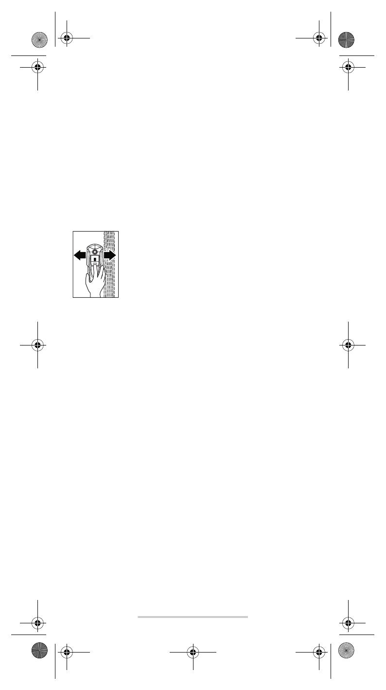
With the “ZOOM” button 4 pressed, evenly move the
measuring tool over the surface without lifting off or chang-
ing the applied pressure. While measuring, the felt pads 8
must always be in contact with the surface.
When a wooden object is detected, an amplitude is dis-
played in the measuring indicator f. Move the measuring
tool over the surface repeatedly to localise the wooden
object more precisely. After moving over the same area
several times, the wooden object can be indicated quite accurately: The
illuminated ring 1 lights up red and a steady tone sounds as long as the
measuring tool is over the wooden object. The measuring indicator f has
the greatest amplitude over the centre of the wooden object. The “Zoom”
measuring indicator e is inactive when scanning for wooden objects.
Caution: When having placed the measuring tool onto the surface to be
scanned under which a wooden object is coincidentally located, and hav-
ing moved it over the surface, the measuring indicator f, the arrow below
the “Zoom” function indicator d and the illuminated ring 1 flash red. In this
case, start the scan again by repositioning the measuring tool somewhat
offset onto the structure and pressing the “ZOOM” button 4 again.
When scanning for wooden objects, metal objects are sometimes also
indicated as objects found at depths between 2050 mm. To distinguish
between wooden and metal objects, switch to the detecting-metal function
(see “Detecting Metal Objects”). When an object is indicated at the same
location in this function, then it is clearly a metal object and not a wooden
object. To continue searching for wooden objects, switch back to the
detecting-wood function.
Scanning for “Live” Wires
The measuring tool indicates lines that carry a voltage between 110 V and
400 V with frequencies corresponding to the widespread standard (AC
with 50 or 60 Hz). Other lines (DC, higher/lower frequency or voltage) are
indicated only as metal objects.
“Live” wires/conductors are indicated both during a metal scan as well as
during a wood scan. When a “live” wire/conductor is detected, the indica-
tor a appears in the display. Move the measuring tool over the surface
repeatedly in order to localise the “live” wire/conductor more precisely.
After moving the measuring tool over the surface several times, the “live”
wire/conductor can be indicated quite precisely. If the measuring tool is
very close to the wire/conductor (four or five bars in indicator a), the illumi-
nated ring 1 flashes red and the signal tone sounds with a rapid tone
sequence.
OBJ_BUCH-1 609 929 J68-001.book Page 4 Monday, January 30, 2006 11:20 AM
English5
1 609 929 J68 30.1.06
“Live” wires/conductors can be detected easier when power consumers
(e.g., lamps, appliances) are connected to the wire/conductor being
sought and switched on. Wires/conductors with 110 V, 230 V and 400 V
(three-phase current) are detected with about the same scan capacity.
Under certain conditions (such as when behind metal surfaces or behind
surfaces with high water content), “live” wires/conductors cannot be
detected with certainty. These ranges can be recognised in the metal
detection function. When a measuring value is indicated all over a larger
range of the measuring indicator f, then the material is screening off elec-
trically and the scan for “live” wires/conductors is not reliable.
Wires that are not “live” can be found as metal objects with the detecting-
metal function. However, stranded cables are not indicated (contrary to
solid copper conductors).
Operating Instructions
B On condition of the principle, the measuring values can be
impaired through certain ambient conditions. These include,
e.g., the proximity of other equipment that produce strong
magnetic or electromagnetic fields, moisture, metallic building
materials, foil-laminated insulation materials or conductive
wallpaper. Therefore, please also observe other information sources
(e.g. construction plans) before drilling, sawing or routing into walls,
ceilings or floors.
Switching Off the Signal Tone
The signal tone can be switched on and off. For this, press the metal-detec-
tion button 6 and the wood-detection button 5 at the same time. When the
signal tone is switched off, the switched-off audio signal indicator j appears
on the display.
The signal tone setting is maintained after switching the measuring tool off
and on again.
Marking Objects
Detected objects can be marked as required. For this, remove the pencil
11 from the measuring tool and carry out the scan as usual. Once you have
found the limits or the centre of an object, simply mark the sought after
location through the marking opening 2.
“AutoCal” Calibration Indicator
When the check mark behind the “AutoCal” calibration indicator g
flashes over a longer period or if it is not displayed anymore, reliable scan-
ning is no longer possible. In this case, send in the measuring tool to an
authorised Bosch after-sales service agent. Exception: In the detecting
wooden objects’ function, the “AutoCal” calibration indicator g goes out
as long as the “ZOOM” button 4 is not pressed.
OBJ_BUCH-1 609 929 J68-001.book Page 5 Monday, January 30, 2006 11:20 AM
English6
1 609 929 J68 30.1.06
Maintenance and Service
Maintenance and Cleaning
When the measuring indicator f continuously shows an amplitude even
though there is no metal object in the vicinity of the measuring tool, the
measuring tool can be calibrated manually. For this, remove all objects in
the vicinity of the measuring tool (including wrist watches or rings of metal)
and hold the measuring tool up in the air. With the measuring tool switched
off, press both the “on/off” button 7 and the wood-detection button 5 until
the illuminated ring 1 lights up red and green at the same time. Then
release both buttons. When the calibration process was successful, the
measuring tool will start over after a few seconds and is then ready for
operation.
Wipe away debris or contamination with a dry, soft cloth. Do not use clean-
ing agents or solvents.
In order not to affect the measuring function, decals/stickers or name
plates, especially metal ones, may not be attached in the sensor area 9 on
the front or back side of the measuring tool.
Do not remove the felt pads 8 on the back side of the measuring tool.
Replace the felt pads when they are damaged or used. For this, completely
remove the felt pads and glue the new felt pads onto the same spots.
Store and transport the measuring tool only in the supplied protective case.
If the measuring tool should fail despite the care taken in manufacturing
and testing procedures, repair should be carried out by an authorized after-
sales service centre for Bosch power tools.
In all correspondence and spare parts orders, please always include the
10-digit article number given on the type plate of the measuring tool.
Spare Parts
Protective case . . . . . . . . . . . . . . . . . . . . . . . . . . . . . . . . . . . 1 609 203 P19
Battery lid 10 . . . . . . . . . . . . . . . . . . . . . . . . . . . . . . . . . . . . . 1 609 203 R32
Felt pads 8. . . . . . . . . . . . . . . . . . . . . . . . . . . . . . . . . . . . . . . 1 609 203 P21
Service and Customer Assistance
Exploded views and information on spare parts can be found under:
www.bosch-pt.com
Great Britain
Robert Bosch Ltd. (B.S.C.)
P.O. Box 98
Broadwater Park
North Orbital Road
Denham-Uxbridge
Middlesex UB 9 5HJ
Service: . . . . . . . . . . . . . . . . . . . . . . . . . . . . . . .+44 (0) 18 95 / 83 87 82
Advice line: . . . . . . . . . . . . . . . . . . . . . . . . . . . .+44 (0) 18 95 / 83 87 91
Fax: . . . . . . . . . . . . . . . . . . . . . . . . . . . . . . . . . . . . .+44 (0) 18 95 / 83 87 89
OBJ_BUCH-1 609 929 J68-001.book Page 6 Monday, January 30, 2006 11:20 AM
English7
1 609 929 J68 30.1.06
Ireland
Beaver Distribution Ltd.
Greenhills Road
Tallaght-Dublin 24
Service: . . . . . . . . . . . . . . . . . . . . . . . . . . . . . . . . +353 (0)1 / 4 14 94 00
Fax: . . . . . . . . . . . . . . . . . . . . . . . . . . . . . . . . . . . . . . +353 (0)1 / 4 59 80 30
Australia and New Zealand
Robert Bosch Australia Pty. Ltd.
RBAU/SPT
1555 Centre Road
P.O. Box 66
3168 Clayton/Victoria
. . . . . . . . . . . . . . . . . . . . . . . . . . . . . . . . . . . . . +61 (0)1 / 3 00 30 70 44
Fax: . . . . . . . . . . . . . . . . . . . . . . . . . . . . . . . . . . . . +61 (0)1 / 3 00 30 70 45
www.bosch.com.au
Disposal
Measuring tools, accessories and packaging should be sorted for environ-
mental-friendly recycling.
Only for EC countries:
Do not dispose of measuring tools into household waste!
According the European Guideline 2002/96/EC for Waste
Electrical and Electronic Equipment and its implementation
into national right, measuring tools that are no longer usable
must be collected separately and disposed of in an environ-
mentally correct manner.
Battery packs/batteries:
Do not dispose of battery packs/batteries into household waste, fire or
water. Battery packs/batteries should be collected, recycled or disposed
of in an environmental-friendly manner.
Only for EC countries:
Defective or dead out battery packs/batteries must be recycled according
the guideline 91/157/EEC.
Batteries no longer suitable for use can be directly returned at:
Great Britain
Robert Bosch Ltd. (B.S.C.)
P.O. Box 98
Broadwater Park
North Orbital Road
Denham-Uxbridge
Middlesex UB 9 5HJ
Service: . . . . . . . . . . . . . . . . . . . . . . . . . . . . . . .+44 (0) 18 95 / 83 87 82
Advice line: . . . . . . . . . . . . . . . . . . . . . . . . . . . .+44 (0) 18 95 / 83 87 91
Fax: . . . . . . . . . . . . . . . . . . . . . . . . . . . . . . . . . . . . .+44 (0) 18 95 / 83 87 89
Subject to change without notice.
OBJ_BUCH-1 609 929 J68-001.book Page 7 Monday, January 30, 2006 11:20 AM
Français1
1 609 929 J68 30.1.06
Description du fonctionnement
Un travail optimal avec cet appareil de mesure n’est
possible que si vous lisez complètement les instruc-
tions d’utilisation et les instructions de travail et que
vous respectiez strictement les indications qui y sont
mentionnées. GARDER PRECIEUSEMENT CES INS-
TRUCTIONS DE SECURITE.
Dépliez le volet sur lequel l’appareil de mesure est repré-
senté de manière graphique. Laissez le volet déplié pendant
la lecture de la présente notice d’utilisation.
Utilisation conforme
L’appareil de mesure est conçu pour détecter les métaux (métaux ferreux
et non-ferreux, tels que les fers d’armature), les poutres en bois ainsi que
les conduites sous tension dans les murs, plafonds et sols.
Eléments de l’appareil
La numérotation des éléments de l’appareil se réfère à la représentation de
l’appareil de mesure sur la page graphique.
1 Anneau luminescent
2 Ouverture de marquage
3 Afficheur
4 Touche « ZOOM »
5 Touche de détection des bois
6 Touche de détection des métaux
7 Interrupteur Marche/Arrêt « on/off »
8 Glisseur en feutre
9 Zone de détection
10 Couvercle du compartiment à piles
11 Crayon pour le marquage (amovible)
12 Blocage du couvercle du compartiment à piles
Eléments d’affichage
a Affichage de conduites électriques sous tension
b Affichage de la fonction Détection de bois
c Affichage de la fonction Détection de métaux
d Affichage de la fonction « ZOOM »
e Affichage de mesure « ZOOM »
f Affichage de mesure
g Affichage de calibrage « AutoCal »
h Affichage de métaux métalliques
i Affichage de métaux non métalliques
j Affichage signal acoustique éteint
k Indicateur de charge de la pile
OBJ_BUCH-1 609 929 J68-001.book Page 1 Monday, January 30, 2006 11:20 AM
Français2
1 609 929 J68 30.1.06
Caractéristiques techniques
Fonctionnement
Mise en place/changement des piles
N’utiliser que des piles ou accus alcalines au manganèse.
Pour ouvrir le couvercle du compartiment à piles 10, appuyer sur le blocage
12 dans le sens de la flèche et relever le couvercle du compartiment à piles.
Introduire la pile fournie. Veiller à la bonne position des pôles qui doit cor-
respondre à la figure se trouvant à l’intérieur du compartiment à piles.
Si l’affichage de piles k s’allume sur l’afficheur, vous disposez encore
d’environ 1 heure pour effectuer des mesurages, si vous utilisez des piles
alcalines au manganèse (les accus ont une durée d’utilisation plus courte).
Si l’affichage k clignote, vous disposez encore d’environ 10 min. pour
effectuer des mesurages. Si l’affichage des piles k et l’anneau luminescent
1 clignotent (rouge), aucun mesurage ne peut être effectué et la pile ou
l’accu doit être remplacé.
B Sortir les piles de l’appareil de mesure au cas où l’appareil ne
serait pas utilisé pendant un certain temps. En cas de stockage
long, la pile peut être corrodée ou se décharger.
Mise en service
Protéger l’appareil de mesure contre l’humidité, ne pas l’exposer
aux rayons directs du soleil.
Mise en Marche/Arrêt
B Avant de mettre en service l’appareil de mesure, s’assurer que
la zone de détection 9 n’est pas humide. Si nécessaire, sécher
l’appareil de mesure à l’aide d’un chiffon.
B Au cas où l’appareil de mesure aurait été exposé à une forte
différence de température, le laisser équilibrer sa température
avant de le mettre en service.
Détecteur numérique PDO Multi
N° d’article 3 603 K10 000
Profondeur max. de détection*:
Métaux ferreux 80 mm
Métaux non-ferreux (cuivre) 60 mm
Conduites en cuivre (sous tension)** 40 mm
Bois 20 mm
Coupure automatique après env. 5 min
Température de service 10 °C ... +50 °C
Température de stockage 20 °C ... +70 °C
Pile 1 x 9 V 6LR61
Accu 1 x 9 V 6F22
Durée de fonctionnement
(avec pile alcaline au manganèse) env. 6 h
Poids suivant EPTA-Procédure 01/2003 0,25 kg
* selon le matériau et la taille des objets ainsi que du matériau et de l’état du support
** profondeur plus faible de détection pour les conduites sans tension
Faire attention au numéro d’article se trouvant sur la plaque signalétique de l’appareil
de mesure. Les désignations commerciales des différents appareils peuvent varier.
OBJ_BUCH-1 609 929 J68-001.book Page 2 Monday, January 30, 2006 11:20 AM
Français3
1 609 929 J68 30.1.06
Pour mettre en service l’appareil de mesure, appuyer sur une touche
quelconque.
Si vous mettez en service l’appareil de mesure à l’aide de la touche de détec-
tion de bois 5 ou à l’aide de la touche de détection de métaux 6, l’appareil se
trouve immédiatement dans la fonction de détection correspondante.
Si vous mettez en service l’appareil de mesure à l’aide de la touche Mar-
che/Arrêt 7 ou la touche « ZOOM » 4, l’appareil se trouve dans la fonction
de détection dans laquelle il a été utilisé la dernière fois.
Après un bref test automatique, l’appareil de mesure est prêt à fonctionner.
Si l’appareil de mesure se trouve dans la fonction détection de métaux, un
crochet derrière l’affichage de calibrage « AutoCal » g indique que l’appa-
reil est prêt à fonctionner.
Pour arrêter l’appareil de mesure, appuyer sur la touche Marche/Arrêt 7.
Si l’on n’appuie sur aucune touche sur l’appareil de mesure pendant env.
5 min, l’appareil s’arrête automatiquement afin de ménager la pile.
Mode opératoire
L’appareil de mesure détecte des objets au-dessous de la zone de détec-
tion 9.
Détection d’objets en métal
Pour détecter des objets en métal, appuyer sur la touche de détection de
métal 6. Le symbole c pour détection de métal est affiché, l’anneau 1
s’allume vert.
Placer l’appareil de mesure sur la surface à examiner et le
déplacer transversalement. Si l’appareil de mesure
s’approche d’un objet métallique, l’oscillation sur l’affi-
cheur f augmente, si l’appareil s’éloigne d’un objet,
l’oscillation diminue. L’objet en métal se trouve au-dessous
du centre du capteur (en dessous de l’ouverture de mar-
quage 2) à l’endroit où l’oscillation est à son maximum.
Tant que l’appareil de mesure se trouve au-dessus de
l’objet en métal, l’anneau 1 est allumé rouge et un signal
acoustique permanent se fait entendre.
Pour une localisation précise de l’objet, appuyer sur la tou-
che « ZOOM » 4 et la maintenir appuyé tout en déplaçant
l’appareil de mesure plusieurs fois (3 fois) sur l’objet. La
fonction Zoom d est affichée. L’oscillation de l’affichage de
mesure Zoom e est à son maximum sur le centre de l’objet
en métal.
Si des objets métalliques très petits ou profondément
enfoncés sont cherchés et que l’affichage de mesure f
n’oscille pas, appuyer sur la touche « ZOOM » 4 et la main-
tenir appuyée tout en continuant à déplacer l’appareil sur cet endroit. Ne
prendre en compte que l’affichage de mesure Zoom e pour la détection.
Au cas où il y aurait des inclusions métalliques dans le matériau à examiner,
l’affichage de mesures f affiche un signal permanent. Appuyer ensuite sur
la touche « ZOOM » 4 et la maintenir appuyée tout en continuant à dépla-
cer l’appareil sur cet endroit. Ne prendre en compte que l’affichage de
mesure Zoom e pour la détection.
Si l’objet en métal détecté est un métal magnétique (par ex. fer), le symbole
h est affiché. Pour les métaux non magnétiques, le symbole i est affiché.
Pour différencier entre les deux types de métaux, l’appareil de mesure doit
se trouver au-dessus de l’objet métallique détecté (l’anneau 1 s’allume
rouge). Pour les faibles signaux l’affichage du type de métaux n’est pas
possible.
OBJ_BUCH-1 609 929 J68-001.book Page 3 Monday, January 30, 2006 11:20 AM
  • Page 1 1
  • Page 2 2
  • Page 3 3
  • Page 4 4
  • Page 5 5
  • Page 6 6
  • Page 7 7
  • Page 8 8
  • Page 9 9
  • Page 10 10
  • Page 11 11
  • Page 12 12
  • Page 13 13
  • Page 14 14
  • Page 15 15
  • Page 16 16
  • Page 17 17
  • Page 18 18
  • Page 19 19
  • Page 20 20
  • Page 21 21
  • Page 22 22
  • Page 23 23
  • Page 24 24
  • Page 25 25
  • Page 26 26
  • Page 27 27
  • Page 28 28
  • Page 29 29
  • Page 30 30
  • Page 31 31
  • Page 32 32
  • Page 33 33
  • Page 34 34
  • Page 35 35
  • Page 36 36
  • Page 37 37
  • Page 38 38
  • Page 39 39
  • Page 40 40
  • Page 41 41
  • Page 42 42
  • Page 43 43
  • Page 44 44
  • Page 45 45
  • Page 46 46
  • Page 47 47
  • Page 48 48
  • Page 49 49
  • Page 50 50
  • Page 51 51
  • Page 52 52
  • Page 53 53
  • Page 54 54
  • Page 55 55
  • Page 56 56
  • Page 57 57
  • Page 58 58
  • Page 59 59
  • Page 60 60
  • Page 61 61
  • Page 62 62
  • Page 63 63
  • Page 64 64
  • Page 65 65
  • Page 66 66
  • Page 67 67
  • Page 68 68
  • Page 69 69
  • Page 70 70
  • Page 71 71
  • Page 72 72
  • Page 73 73
  • Page 74 74
  • Page 75 75
  • Page 76 76
  • Page 77 77
  • Page 78 78
  • Page 79 79
  • Page 80 80
  • Page 81 81
  • Page 82 82
  • Page 83 83
  • Page 84 84
  • Page 85 85
  • Page 86 86
  • Page 87 87
  • Page 88 88
  • Page 89 89
  • Page 90 90
  • Page 91 91
  • Page 92 92
  • Page 93 93
  • Page 94 94
  • Page 95 95
  • Page 96 96
  • Page 97 97
  • Page 98 98
  • Page 99 99

Bosch PDO Multi 取扱説明書

タイプ
取扱説明書