
DW745

2
Copyright D
EWALT
hsilgnE (original instructions) 4
10
16
简体中文

11
A2
A1
1
5 6 7 8 9
43
10
2 12 11
13 14 15 16 17
18

22
6
27
28 29 30
5
726
25
24
22 23
21
21 20
19
E
B2
C
A3
B1
B3
D
F1
45
0
31
33
32

33
1548
36
37
41
43
42
19
40
36 37
3938
12
35
34
9
I
F2
G2
G1
H
J
45 44
K
L
46
47

4
E N GLI S H
TABLE SAW DW745
Voltage V 220
Motor power (input) W
1850
Motor power (output) W 1100
No-load speed min
-1
3800
Blade diameter mm 250
Blade bore mm 30
Blade body thickness mm
2.0
Riving knife thickness mm 2.3
Depth of cut at 90° mm 77
Depth of cut at 45° mm 57
Ripping capacity mm
610
Overall dimensions cm 570 x 700 x 466
Weight kg 21.5
Congratulations!
You have chosen a DEWALT tool. Years of experience, thorough product
development and innovation make D
EWALT one of the most reliable
partners for professional power tool users.
Technical Data
NOTE: Switching activity may produce short-term voltage changes or
fluctuations. Under unfavourable conditions in public low-voltage supply
systems impairment of other appliances might appear. Disturbances will
not occur if the impedance is less than 0.25 Ohms. Sockets used for
these power tools shall be fused with 16 Amperes cut-out with an inert
characteristic.
Defi nitions: Safety Guidelines
The definitions below describe the level of severity for each signal word.
Please read the manual and pay attention to these symbols.
DANGER: Indicates an imminently hazardous situation which, if
not avoided, will result in death or serious injury.
WARNING: Indicates a potentially hazardous situation which, if
not avoided, could result in death or serious injury.
CAUTION: Indicates a potentially hazardous situation which, if
not avoided, may result in minor or moderate injury.
NOTICE: Indicates a practice not related to personal injury
which, if not avoided, may result in property damage.
Denotes risk of electric shock.
Denotes risk of fire.
Sharp edges.
Safety Instructions
When using stationary power tools, always observe the safety
regulations applicable in your country to reduce the risk of fire,
electric shock and personal injury.
Read all of this manual carefully before operating the tool.
Save this manual for future reference.
General
1 Keep work area clean
Cluttered areas and benches can cause accidents.
2 Consider work area environment
Do not expose the tool to rain. Do not use the tool in damp or wet
conditions. Keep the work area well lit (250 - 300 Lux). Do not use
the tool where there is a risk of causing fire or explosion, e.g. in the
presence of fiammable liquids and gases.
3 Keep children away
Do not allow children, visitors or animals to come near the work area
or to touch the tool or the mains cable.
4 Dress properly
Do not wear loose clothing or jewellery, as these can be caught in
moving parts. Wear protective hair covering to keep long hair out of
the way. When working outdoors, preferably wear suitable gloves
and non-slip footwear.
5 Personal protection
Always use safety glasses. Use a face or dust mask whenever the
operations may produce dust or fiying particles. If these particles
might be considerably hot, also wear a heat-resistant apron. Wear
ear protection at all times. Wear a safety helmet at all times.
6 Guard against electric shock
Prevent body contact with earthed or grounded surfaces (e.g. pipes,
radiators, cookers and refrigerators). When using the tool under
extreme conditions (e.g. high humidity, when metal swarf is being
produced, etc.), electric safety can be improved by inserting an
isolating transformer or a (FI) earth-leakage circuit-breaker.
7 Do not overreach
Keep proper footing and balance at all times.
8 Stay alert
Watch what you are doing. Use common sense. Do not operate the
tool when you are tired.
9 Secure workpiece
Use clamps or a vice to hold the workpiece. It is safer and it frees
both hands to operate the tool.
10 Connect dust extraction equipment
If devices are provided for the connection of dust extraction and
collection facilities, ensure that these are connected and properly
used.
11 Remove adjusting keys and wrenches
Always check that adjusting keys and wrenches are removed from
the tool before operating the tool.
12 Extension cables
Before use, inspect the extension cable and replace if damaged.
When using the tool outdoors, only use extension cables intended for
outdoor use and marked accordingly.
13 Use appropriate tool
The intended use is described in this instruction manual. Do not force
small tools or attachments to do the job of a heavy-duty tool. The tool
will do the job better and safer at the rate for which it was intended.
Do not force the tool.
Warning! The use of any accessory or attachment or performance of
any operation with this tool other than those recommended in this
instruction manual may present a risk of personal injury.
14 Check for damaged parts
Before use, carefully check the tool and mains cable for damage.
Check for misalignment and seizure of moving parts, breakage of
parts, damage to guards and switches and any other conditions that
may affect its operation. Ensure that the tool will operate properly
and perform its intended function. Do not use the tool if any part is
damaged or defective. Do not use the tool if the switch does not turn
it on and off. Have any damaged or defective parts replaced by an
authorised D
EWALT repair agent. Never attempt any repairs yourself.
DW745

5
E N G L I S H
16 Avoid unintentional starting
Be sure that the tool is switched off before plugging in.
17 Do not abuse cord
Never pull the cord to disconnect from the socket. Keep the cord
away from heat, oil and sharp edges.
18 Store idle tools
When not in use, tools must be stored in a dry place and locked up
securely, out of reach of children.
19 Maintain tools with care
Keep the tools in good condition and clean for better and safer
performance. Follow the instructions for maintenance and changing
accessories. Keep all handles and switches dry, clean and free from
oil and grease.
20 Repairs
This tool is in accordance with the relevant safety regulations. Have
your tool repaired by an authorised D
EWALT repair agent. Repairs
should only be carried out by qualified persons using original spare
parts; otherwise this may result in considerable danger to the user.
Additional safety rules for saw benches
• Do not use saw blades with a body thickness greater or a width of
tooth smaller than the thickness of the riving knife.
• Make sure that the blade rotates in the correct direction and that the
teeth are pointing to the front of the saw bench.
• Be sure all clamp handles are tight before starting any operation.
• Be sure all blade and fianges are clean and the recessed sides of the
collar are against the blade. Tighten the arbor nut securely.
• Keep the saw blade sharp and properly set.
• Make sure that the riving knife is adjusted to the correct distance
from the blade - maximum 5 mm.
• Never operate the saw without the upper and lower guards in place.
• Keep your hands out of the path of the saw blade.
• Disconnect the saw from the mains supply before changing blades or
carrying out maintenance.
• Use a push stick at all times, and ensure that you do not place hands
closer than 150 mm from the saw blade while cutting.
• Do not attempt to operate on anything but the designated voltage.
• Do not apply lubricants to the blade when it is running.
• Do not reach around behind the saw blade.
• Always keep the push stick in its place when not in use.
• Do not stand on top of the unit.
• During transportation make sure that the upper part of the saw blade
is covered, e.g. by the guard.
• Do not use the guard for handling or transportation.
• Immediately replace the table insert when worn or damaged.
• Check that the workpiece is properly supported. Always provide
additional support for long workpieces.
• Do not exert side pressure on the saw blade.
• Never cut light alloy. The machine is not designed for this application.
• Do not use abrasive disc or diamond cutting wheels
• Rebating, slotting or grooving is not allowed.
• In case of an accident or machine failure, immediately switch the
machine off and pull the plug. Report the failure and mark the
machine in suitable form which prevents that other persons use the
defective machine.
• When the saw blade is blocked due to abnormal feed force during
cutting, ALWAYS switch the machine off and disconnect from power
supply. Remove the workpiece and ensure that the saw blade runs
free. Turn the machine on and start a new cutting operation with
reduced feed force.
• Pull the plug from the socket when blade change or any maintenance
is needed.
• Wear always hear protection.
• Wear always safety glasses
• Wear always dust mask when sawing wood.
• Faults in the machine, including guards and saw blades, shall be
reported as soon as they are discovered.
Saw blades
• The max. allowable speed of the saw blade must always be equal to or
greater than the no-load speed of the tool specified on the nameplate.
• Do not use saw blades that do not conform to the dimensions stated
in the technical data. Do not use any spacers to make a blade fit onto
the spindle. Use only the blades specified in this manual, complying
with EN 847-1.
• Consider applying specially designed noise-reduction blades.
• Do not use HS blades.
• Do not use cracked or damaged saw blades.
• Ensure that the chosen saw blade is suitable for the material to be
cut.
• Always wear gloves for handling saw blades and rough material.
Saw blades should be carried in a holder wherever practicable.
Residual risks
The following risks are inherent to the use of saws:
- injuries caused by touching the rotating parts
In spite of the application of the relevant safety regulations and the
implementation of safety devices, certain residual risks cannot be
avoided. These are:
- Impairment of hearing.
- Risk of accidents caused by the uncovered parts of the rotating saw
blade.
- Risk of injury when changing the saw blade with unprotected hands.
- Risk of squeezing fingers when opening the guards.
15 Unplug tool
Switch off and wait for the tool to come to a complete standstill
before leaving it unattended. Unplug the tool when not in use,
before changing any parts of the tools, accessories or attachments
and before servicing.
- Health hazards caused by breathing dust developed when sawing
wood, especially oak, beech and MDF.
The following factors are of infiuence to noise production:
- the material to be cut
- the type of saw blade
- the feed force
- machine maintenance
The following factors are of infiuence to dust exposure:
- worn saw blade
- dust extractor with air velocity less than 20 m/s
-
workpiece not exactly guided
Under consideration of the factors mentioned above, the dust collecting
ef ciency is about 95% of breathable dust.
Markings on Tool
The following pictograms are shown on the tool:
Read instruction manual before use.
Wear ear protection.
Wear eye protection.
Wear respiratory protection.

6
E N G L I S H
Pull the plug from the socket when blade change or any
maintenance is needed.
Keep hands away from cutting area and the blade.
Carrying point.
DATE CODE POSITION
The Date Code, which also includes the year of manufacture, is printed
into the housing.
Example:
2012 XX XX
Year of Manufacture
Package contents
The package contains:
1 Partly assembled machine
1 Rip fence assembly
1 Mitre fence
1 Upper blade guard assembly
1 Table insert
1 Blade wrench
1 Arbor wrench
1 Dust extraction adapter
1 Instruction manual
1 Exploded drawing
• Check for damage to the tool, parts or accessories which may have
occurred during transport.
• Take the time to thoroughly read and understand this manual prior to
operation.
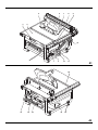
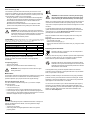
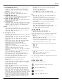
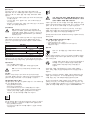
Description (fi g. A1 - A3)
A1
1 On/off switch
2 Circuit breaker reset button
3 Hand indentation
4 Table
5 Riving knife
6 Upper blade guard
7 Table insert
8 Parallel rip fence
9 Rip scale indicator
10 Fine adjustment knob
11 Combined elevating and bevel control wheel
12 Bevel lock lever
A2
13 Ripping position lock lever
14 Blade wrench storage
15 Push stick
16 Dust extraction adapter
17 Foot
18 Fence slot
A3
19 Mitre fence
INTENDED USE
Your DW745 jobsite table saw has been designed to perform the sawing
operation of ripping, cross-cutting,
bevelling and mitring in wood, wood
products and plastics. This unit is designed for use with a ø 250 mm
carbide tip blade.
WARNING: Do not use the machine for other purposes as
intended.
DO NOT use under wet conditions or in presence of flammable liquids or
gases.
These table saws are professional power tools.
DO NOT let children come into contact with the tool. Supervision is
required when inexperienced operators use this tool.
• This product is not intended for use by persons (including children)
suffering from diminished physical, sensory or mental abilities; lack of
experience, knowledge or skills unless they are supervised by a person
responsible for their safety. Children should never be left alone with this
product.
Electrical safety
The electric motor has been designed for one voltage only. Always check
that the power supply corresponds to the voltage on the rating plate.
Your DEWALT tool is double insulated in accordance with
EN 61029; therefore no earth wire is required.
If the supply cord is damaged, it must be replaced by a specially prepared
cord available through the D
EWALT service organisation.
Using an Extension Cable
If an extension cable is required, use an approved 3–core extension cable
suitable for the power input of this tool (see Technical Data).The minimum
conductor size is 1.5 mm
2
; the maximum length
is 30 m.
When using a cable reel, always unwind the cable completely.
Assembly and adjustment
WARNING: Prior to assembly and adjustment always unplug
the tool.
Unpacking (fig. A1 & A2)
• Remove the saw from the packaging material carefully.
• The machine is fully assembled except for the blade, rip fence, upper
blade guard and table insert.
• Finalise the assembly following the instructions as described below.
• Put the push stick (15) on its place at the right-hand side of the
machine (fig. A2).
• Adjust the feet (17) until the table (4) is level in all directions.
• Fully unwind the mains cable.
WARNING:
• Always keep the push stick in its place when not in use.
• Connect the plug to the mains outlet only just before starting
the application.
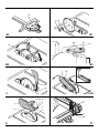
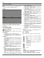
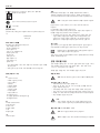
Mounting the saw blade (fig. A1, A2 & B1 - B3)
WARNING: Ensure the machine is disconnected from the
power source.
WARNING: The teeth of a new blade are very sharp and can
be dangerous.

7
E N G L I S H
• Raise the blade arbor to its maximum by rotating the control wheel (11)
clockwise (fig. A1).
• Place the saw blade onto the spindle in the order shown in figure B1.
The outer fiange (20) has a ø 30 mm raised boss which fits inside the
blade bore. Make sure the teeth point down at the front of the table.
• Hold the spindle using the open-ended wrench and tighten the arbor
nut (21) by rotating clockwise using the arbor wrench (fig. B2).
• To remove the blade, proceed in reverse order.
WARNING: Always check the rip fence pointer and the riving knife after
having changed the blade.
Adjusting the saw blade (fig. A2 & B3)
For optimum performance, the blade must be parallel to the mitre slots.
This adjustment has been made at the factory. To re-adjust:
• Turn the saw on its side.
• Using a 10 mm Allen key, slacken the bracket fasteners (22) slightly
(fig. B3).
• Adjust the bracket (23) until the blade is parallel to the fence slot (18)
(fi g. A2).
• Tighten the bracket fasteners (22) to 11 Nm (fig. B3).
Blade height adjustment (fi g. A1)
The blade can be raised and lowered by turning the combined elevating
and bevel control wheel (11).
• Make sure the top three teeth of the blade are just breaking through
the upper surface of the workpiece when sawing. This will ensure
that the maximum number of teeth are removing material at any
given time, thus giving optimum performance.
Mounting the riving knife (fi g. A1 & C)
• Raise the blade arbor to its maximum by rotating the blade height
adjustment wheel (11) clockwise (fi g. A1).
• Slacken the locking bolt (24) a few turns using the supplied wrench
(fi g. C).
• Push and hold the bolt (24) inwards to release the spring-loaded
clamping mechanism.
• Align the slot (25) with the bolt (24) and insert the riving knife until the
top of the slot rests on the knob.
• Release the bolt (24) and tighten securely using the supplied wrench.
WARNING:
• When properly aligned, the riving knife will be in line with the
blade at the table top and at the top of the blade. Check
using a straight edge in all bevel and blade height positions.
• Do not attempt to fix the riving knife in any other position
than recommended. The distance between the riving knife
and the tips of the blade teeth must be at least 2.0 mm.
• Correct mounting and alignment of the upper blade guard (6)
on the riving knife is essential to safe operation!
• It is not allowed to fit a different riving knife to the
specification delivered with a thickness of 2.3 mm.
Fixing to Workbench (fi g. A2)
• The machine frame between the feet on each side (17) is provided
with two holes which allow fixing on a workbench. Use the holes
diagonally.
• To improve the handling fix the machine on a piece of plywood of min
15 mm thick.
• When in use the plywood sheet can be clamped to the workbench.
This allows easier transportation of the machine, by releasing the
clamps.
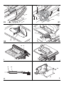
Mounting the table insert (fi g. D)
• Align the table insert (7) as shown and insert the tabs of the back of
the table insert into the holes on the back of the table.
• Press down the front of the table insert.
• The front of the table insert must be fiush or slightly below the table
top. The rear should be fiush with the table top. Adjust using the four
adjustment screws (26).
• Turn the locking screw (see insert in fi g. D) clockwise 90° to lock the
table insert in place.
WARNING: Never use the machine without the table insert. Immediately
replace the table insert when worn or damaged.
Mounting the upper blade guard (fi g. E)
• Fasten the guard (6) to the riving knife (5) with the bolt (27).
• Place the washer (28 & 29) and wingnut (30) onto the other end of
the bolt and tighten.
WARNING: The saw blade MUST be replaced as described
in this section. ONLY use saw blades as specified under
Technical Data. We suggest DT4226. NEVER fit other saw
blades.
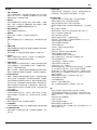
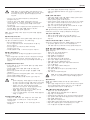
Mounting and adjusting the parallel fence (fi g. A1, F1 & F2)
The rip fence (8) can be installed on the left or right side of your table
saw.
• Locate the screw (31) with the slot (32) in the rip fence.
• Secure the rip fence by snapping both latches (33) in place.
Adjusting the fence parallel to the blade
The fence has been factory-set. If you need to re-adjust, proceed as
follows:
• Set the saw blade to its highest position.
• Remove the upper blade guard (6).
• Set the bevel angle to 0°.
• Unlock the rail lock lever (13).
• Move the fence (8) until it touches the blade.
• Check that the fence is parallel to the blade.
• If adjustment is required, proceed as follows:
• Using an Allen key, loosen the adjustment screw (31) locating the
fence to the fence rail.
• Adjust the fence parallel to the blade.
• Tighten the adjustment screw.
• Lock the rail lock lever and check that the fence is parallel to the
blade.
• Be sure to replace the blade guard after the adjustment.
WARNING: If there is not enough travel in the pinion bearing
assembly, take the unit to an authorized D
EWALT repair
agent.
Adjusting the rip scale
The rip scale reads correctly only when the fence is mounted to the right
of the blade.
• Check that the pointer (9) indicates zero on the scale when the fence
is just touching the blade. If the pointer does not indicate exactly
zero, loosen the screws (34), move the pointer to read 0 and tighten
the screws.
Bevel stop and pointer adjustment (fig. G1 & G2)
• Set the saw blade to its highest position.
• Unlock the bevel lock lever (12) by pushing it up and to the right.
• Loosen the bevel stop screw (35).
• Place a set square (36) on the table and up against the blade (37).
• Adjust the bevel angle using the bevel lock lever (12) until the blade
is fiat against the square.
• Tighten the bevel lock lever (12).
• Turn the bevel stop cam (38) until it firmly contacts the bearing block.
• Check the bevel angle scale. If adjustment is required, loosen the
pointer screw (39) and set the pointer to 0°.

8
E N G L I S H
• Tighten the pointer screw (39).
• Repeat the procedure at 45° for the 45° bevel stop, but do not adjust
the pointer.
Adjusting the mitre fence (fi g. H)
• Install the mitre fence (19) in the slot to the left of the blade.
• Loosen the lock knob (40).
• Place a square (36) against the fence face (41) and the blade (37).
• Check that the pointer (42) indicates 90° on the scale. If the pointer
does not indicate exactly 90°, loosen the screw (43), move the
pointer to read 90° and tighten the screw.
OPERATION
Instructions for use
WARNING:
• Always observe the safety instructions and applicable
regulations.
• Ensure the machine is placed to satisfy ergonomic conditions
in terms of table height and stability. The machine site shall
be chosen so that the operator has a good overview and
enough free surrounding space around the machine that
allow handling of the workpiece without any restrictions.
• Install the appropriate saw blade. Do not use excessively
worn blades. The maximum rotation speed of the tool must
not exceed that of the saw blade.
• Do not attempt to cut excessively small pieces.
• Allow the blade to cut freely. Do not force.
• Allow the motor to reach full speed before cutting.
• Make sure all locking knobs and clamp handles are tight.
The attention of UK users is drawn to the "woodworking machines
regulations 1974" and any subsequent amendments.
• Never place either hand in the blade area when the saw is connected
to the electrical power source.
• Never use your saw for freehand cuts!
• Do not saw warped, bowed or cupped workpieces. There must be at
least one straight, smooth side to go against the rip fence or mitre
fence.
• Always support long workpieces to prevent kickback.
• Do not remove any cut-offs from the blade area while the blade is
running.
Switching on and off (fi g. A1)
• To switch the machine on, press the green start button.
• To switch the machine off, press the red stop button.
NOTE: Switching activity may produce short-term voltage changes or
fiuctuations. Under unfavourable conditions in public low-voltage supply
systems impairment of other appliances might appear. Disturbances will
not occur if the impedance is less than 0.262 Ohms.
Sockets used for these power tools shall be fused by a 16 Amperes
cut-out with an inert characteristic.
Basic saw cuts
• Always use the riving knife.
• Always ensure that the riving knife and blade guard are correctly
aligned.
Ripping (fi g. A1 & I)
WARNING: Sharp edges.
• Set the bevel angle to 0°.
• Adjust the saw blade height. The correct blade position is to have the
tips of three teeth just protruding through the top surface of the wood.
Adjust the height of the upper blade guard as necessary.
• Set the parallel fence to the required distance.
• Adjust the position of the L-shaped fence profile (48) level with the
back of the riving knife. When ripping wide pieces of material, slide
the L-shaped fence profile (48) off the main part of the fence, rotate
vertically through 180° and replace to provide additional support.
• Hold the workpiece fiat on the table and against the fence. Keep the
workpiece away from the blade.
• Keep both hands away from the path of the blade.
• Switch the machine on and allow the blade to reach full speed.
• Slowly feed the workpiece underneath the guard, keeping it firmly
pressed against the rip fence. Allow the teeth to cut, and do not force
the workpiece through the blade. The blade speed should be kept
constant.
• Remember to use the push stick (15) when close to the blade.
• After completing the cut, switch the machine off, allow the blade to
stop and remove the workpiece.
WARNING:
• Never push or hold the "free" or cut-off-side of the workpiece.
• Do not cut excessively small workpieces.
• Always use a push stick when ripping small workpieces.
Bevel cuts
• Set the required bevel angle.
• Proceed as for ripping.
Cross-cutting (fi g. J)
• Remove the rip fence and install the mitre fence in the desired slot.
• Lock the mitre fence at 0°.
• Set the bevel angle to 0°.
• Adjust the saw blade height.
• Hold the workpiece fiat on the table and against the fence. Keep the
workpiece away from the blade.
• Keep both hands away from the path of the saw blade.
• Switch the machine on and allow the saw blade to reach full speed.
• Hold the workpiece tightly against the fence and slowly move the
workpiece together with the fence assembly until the workpiece
comes underneath the upper blade guard. Allow the teeth to cut, and
do not force the workpiece through the saw blade. The saw blade
speed should be kept constant.
• After completing the cut, switch the machine off, allow the saw blade
to stop and remove the workpiece.
Bevel cross-cutting
• Set the required bevel angle.
• Proceed as for cross-cutting.
Mitre cuts
• Set the mitre fence to the required angle.
• Proceed as for cross-cutting.
Compound mitre
This cut is a combination of a mitre and a bevel cut.
• Set the bevel to the angle required and proceed as for a cross-cut mitre.
Support for long pieces
• Always support long pieces.
• Support long workpieces using any convenient means such as
saw-horses or similar devices to keep the ends from dropping.

9
E N G L I S H
Dust extraction (fig. A2)
The machine is provided with a dust exhaust port at the rear of the
machine (16) suitable for use with dust extraction equipment featuring
57/65 mm nozzles. Supplied with the machine is a reducer port for use
of dust extraction nozzles of 34-40 mm diameter.
• During all operations, connect a dust extraction device designed in
accordance with the relevant regulations regarding dust emission.
• Ensure that the dust extraction hose in use is suitable for the
application and material being cut.
• Be aware that man-made materials such as chipboard or MDF
produce more dust particles during cutting than natural timber.
Optional accessories
WARNING: Since accessories, other than those offered by
D
EWALT, have not been tested with this product, use of such
accessories with this tool could be hazardous. To reduce the
risk of injury, only D
EWALT, recommended accessories
should be used with this product.
SAW BLADES: ALWAYS USE 250 mm noise reduced saw blades 30 mm
arbour holes. Blade speed rating must be al least 4000 RPM. Never use a
smaller diameter blade. It will not be guarded properly.
BLADE DESCRIPTIONS
HTEETRETEMAIDNOITACILPPA
Construction Saw Blades (fast rip)
42mm 052esopruP lareneG
04mm 052stucssorC eniF
Woodworking Saw Blades (provide smooth, clean cuts)
06mm 052stucssorc eniF
Replace top guard (part no.: 247678-02) when worn.
Consult your dealer for further information on the appropriate
accessories.
Transporting (fig. A1)
• Tidy the mains cable
• Always carry the machine at the hand indentations (3).
WARNING: Always transport the machine with the upper
blade guard fitted.
Maintenance
Your DEWALT machine has been designed to operate over a long period
of time with a minimum of maintenance. Continuous satisfactory
operation depends upon proper tool care and regular cleaning.
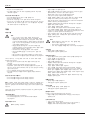
Rail lock adjustment (fi g. A2 & K)
The rail lock tension has been factory-set. If you need to re-adjust,
proceed as follows:
• Turn the saw on its side.
• Lock the lock lever (13).
• Locate the hex rod (44) on the underside of the machine (fig. K).
• Loosen the jam nut (45). Tighten the hex rod until the spring on the
locking system is compressed creating the desired tension on the rail
lock lever. Retighten the jam nut against the hex rod.
Lubrication
The motor and bearings require no additional lubrication. If raising and
lowering the blade becomes difficult, clean and grease the height
adjustment screws:
• Turn the saw on its side.
• Clean and grease the height adjustment threads. Use general
purpose grease.
Cleaning
WARNING: To reduce the risk of serious personal injury,
turn unit off and disconnect machine from power source
before cleaning. An accidental start-up can cause injury.
Before use, carefully inspect upper and lower guard as well as the dust
extraction tube to determine that it will operate properly. Ensure that
chips, dust or workpiece particles cannot lead to blockage of one of the
functions.
In case workpiece fragments are jammed between saw blade and
guards, disconnect the machine from the power supply and follow the
instructions given in section Mounting the saw blade. Remove the
jammed parts and reassemble the saw blade.
Keep the ventilation slots clear and regularly clean the housing with
a soft cloth.
Regularly clean the dust collection system (fi g. L):
• Turn the saw on its side.
• Remove the screws (46) (fi g. L).
• Remove all dust and resecure the access door (47) using the screws
(fig. L).
Protecting the environment
Separate collection. This product must not be disposed of
with normal household waste.
Should you find one day that your D
EWALT product needs replacement,
or if it is of no further use to you, do not dispose of it with household
waste. Make this product available for separate collection.
Separate collection of used products and packaging allows
materials to be recycled and used again. Re-use of recycled
materials helps prevent environmental pollution and reduces
the demand for raw materials.
Local regulations may provide for separate collection of electrical
products from the household, at municipal waste sites or by the retailer
when you purchase a new product.
D
EWALT provides a facility for the collection and recycling of DEWALT
products once they have reached the end of their working life. To take
advantage of this service please return your product to any authorised
repair agent who will collect them on our behalf.
You can check the location of your nearest authorised repair agent by
contacting your local D
EWALT offi ce at the address indicated in this
manual. Alternatively, a list of authorised D
EWALT repair agents and full
details of our after-sales service and contacts are available on the
Internet at: www.2helpU.com

中文
DW745 型台锯
恭喜!
您选购的是
DEWALT
设备!多年的经验积淀,全面细致的产品开发和创
新,让
DEWALT
成为电动工具专业用户最可靠的伙伴之一。
技术参数
注:
接通和断开开关时可能会产生短时间的电压变化或波动。在公共低压
电网出现不利情况时,其他电器设备可能会发生损坏。如果阻抗小于
0.25
欧姆,则不会干扰到本设备。这些电动工具使用的插座应带有
16
安
本安型熔断器。
电动工具通用安全警告
警告!阅读所有警告和所有说明。不遵照以下警告和说明会导致电
击、着火和/或严重伤害。
保存所有警告和说明书以备查阅。
在所有下列的警告中术语“电动工具”指市电驱动(有线)电动工具或电
池驱动(无线)电动工具。
a)
工作场地的安全
1)
保持工作场地清洁和明亮。混乱和黑暗的场地会引发事故。
2)
不要在易爆环境动工具。电动工具产生的火花会点燃粉尘或气体。
3)
让儿童和旁观者离开后操作电动工具。注意力不集中会使你失去对
工具的控制。
b)
电气安全
1)
电动工具插头必须与插座相配。绝不能以任何方式改装插头。需接
地的电动工具不能使用任何转换插头。未经改装的插头和相配的插
座将减少电击危险。
2)
避免人体接触接地表面,如管道、散热片和冰箱。如果你身体接地
会增加电击危险。
3)
不得将电动工具暴露在雨中或潮湿环境中。水进入电动工具将增加
电击危险。
4)
不得滥用电线。绝不能用电线搬运、拉动电动工具或拔出其插头。
使电线远离热源、油、锐边或运动部件。受损或缠绕的软线会增加
电击危险。
5)
当在户外使用电动工具时,使用适合户外使用的外接软线。适合户
外使用的软线将减少电击危险。
6)
如果在潮湿环境下操作电动工具是不可避免的,应使用剩余电流动
作保护器(
RCD
)。使用
RCD
可减小电击危险。
c)
人身安全
1)
保持警觉,当操作电动工具时关注所从事的操作并保持清醒。当你
感到疲倦,或在有药物、酒精或治疗反应时,不要操作电动工具。
在操作电动工具时瞬间的疏忽会导致严重人身伤害。
2)
使用个人防护装置。始终佩戴护目镜。安全装置,诸如适当条件下
使用防尘面具、防滑安全鞋、安全帽、听力防护等装置能减少人身
伤害。
3)
防止意外起动。确保开关在连接电源和 / 或电池盒、拿起或搬运工
具时处于关断位置。手指放在已接通电源的开关上或开关处于接通
10
时插入插头可能会导致危险。
4)
在电动工具接通之前,拿掉所有调节钥匙或扳手。遗留在电动工具
旋转零件上的扳手或钥匙会导致人身伤害。
5)
手不要伸展得太长。时刻注意立足点和身体平衡。这样在意外情况
下能很好地控制电动工具。
6)
着装适当。不要穿宽松衣服或佩戴饰品。让你的衣服、手套和头发
远离运动部件。宽松衣服、佩饰或长发可能会卷入运动部件中。
7)
保持手干燥,清洁且没有油脂。油腻的手柄对于意外情况下的工具
安全握持和控制是不允许的。
8)
如果提供了与排屑、集尘设备连接用的装置,要确保他们连接完好
且使用得当。使用这些装置可减少尘屑引起的危险。
d)
电动工具使用和注意事项
1)
不要滥用电动工具,根据用途使用适当的电动工具。选用适当设计
的电动工具会使你工作更有效、更安全。
2)
如果开关不能接通或关断工具电源,则不能使用该电动工具。不能
用开关来控制的电动工具是危险的且必须进行修理。
3)
在进行任何调节、更换附件或贮存电动工具之前,必须从电源上拔
掉插头和/或使电池盒与工具脱开。这种防护性措施将减少工具意
外起动的危险。
4)
将闲置不用的电动工具贮存在儿童所及范围之外不熟悉电动工具或
对这些说明不了解的人操作电工具在未经培训的用户手中是危险
的。
5)
保养电动工具。检查运动件是否调整到位或卡住,检查零件破损情
况和影响电动工具运行的其他状况。如有损应在使用前修理好。许
多事故由维护不良的电动工具引发。
6)
保持切削刀具锋利和清洁。保养良好的有锋利切削刃的刀具不易卡
住而且容易控制。
7)
按照使用说明书,考虑作业条件和进行的作业来使用电动工具、附
件和工具的刀头等。将电动工具用于那些与其用途不符的操作可能
会导致危险。
e)
维修
将你的电动工具送交专业维修人员,使用同样的备件进行修理。这样
将确保所维修的电动工具的安全性。
定义:安全准则
以下定义说明每个信息词表示的严重程度。请阅读本手册,并留意以下
符号。
危险:
表示紧急危险状况,如果不加避免,
将
导致
死亡或
重伤。
警告:
表示潜在危险状况,如果不加避免,
可能
导致
死亡
或重伤
。
小心:
表示潜在危险状况,如果不加避免,
可
导致
轻微或
中等程度的伤害
。
注意:
表示不会
造成个人伤害
的做法,如果不加避免,
可
能
会造成
财产损失
。
表示存在电击风险。
表示存在火灾风险。
锐利边缘。
安全须知
使用固定式电动工具时,应始终遵守所在国家或地区的适用安全规范,
以减少火灾、电击以及个人伤害发生的风险。
操作设备前,请仔细通读本手册。保存好本手册,以便日后参考。
DW745
电压
V 220
电机功率(输入)
W 1850
电机功率(输出)
W 1100
空转转速
min
-1
3800
锯片直径
mm 250
锯片孔径
mm 30
锯片厚度
mm 2.0
跟刀板厚度
mm 2.3
切割深度/90° mm 77
切割深度/45° mm 57
最大纵切宽度
mm 610
外形尺寸
cm 570 x 700 x 466
机重
kg 21.5

要点说明
1
注意工作区域环境
不得让本设备受到雨淋。不得在潮湿环境中使用本设备。工作区域照
明充分
(250 - 300 Lux)
。不得在存在火灾或爆炸风险(例如,如存在
易燃液体和气体)的场所使用本设备。
2
防范电击
防止身体接触接地表面(例如管道、暖器、炊具和冰箱等)。在极端
条件下(例如,大湿度且产生金属屑等情况)使用本设备时,加装隔
离变压器或
(FI)
接地漏电断路器能够增强电气安全。
3 保持正确操作姿势
始终立足稳固并且保持身体平衡。
4 保持警惕
集中精力操作。运用常识。不得在疲劳时操作本设备。
5 固定工件
使用卡钳或台钳固定住工件。这种做法更安全,可解放双手以利于操
作
设备。
6 连接吸尘设备
如果设备能够连接吸尘和集尘装置,确保这类装置连接正确,使用得当。
7 取出调节钥匙和扳手
操作本设备前,务必检查调节钥匙和扳手是否已从本设备上取下。
8 加长电线
使用前,检查加长电线,如有损坏,应予更换。在户外使用设备时,
只能使用户外专用且带有相应标识的加长电线。
9 正确使用本设备
本操作说明手册介绍了设备的规定用途。不得强行使用小型设备或配
件完成大型设备作业。在设计额定参数下工作时,本设备性能更佳,
也更安全。不得超荷使用本设备。
警告!对于本设备,如使用本操作说明手册推荐范围以外的任何附件
或配件,或者进行推荐范围以外的任何操作,可能造成人员伤害风险。
10 检查有无损坏零件
使用前,仔细检查本设备和电源线是否存在损坏。检查运动部件是否
没有对正或卡住、零件是否断裂、防护罩和开关是否损坏,检查是否
存在可能影响本设备运转的其他任何状况。确保本设备正常运转并且
执行其设计功能。如果任何零件损坏或者存在缺陷,不得使用本设备。
如果开关失效不能打开或关停设备,不得使用本设备。任何损坏或存
在缺陷的零件均须由
DEWALT
授权维修人员更换。切勿尝试自己动手
进行任何维修。
11 拔掉设备电源插头
关闭设备并且待其完全停止后,方可离开。设备不使用时,或在更换
设备的任何零部件、附件或配件之前,或在进行检修之前,应拔掉电
源插头。
12 防止设备意外启动
确保本设备处于关闭状态,然后再插入电源插头。
13 正确使用电线
不得拉着电线将插头从插座上拉出。电线要远离热源、机油及锐利边缘。
14 不使用时设备的存放
设备不使用时,必须将其存放在干燥、儿童场触及不到的场所,并且
安全上锁。
中文
15 认真保养设备
保持设备完好整洁,使其性能更佳,也更安全。按照操作说明进行保
养及更换附件。所有手柄和开关保持干燥整洁,不存在油污。
更多台锯安全规则
•
不得使用刀体厚度大于或者锯齿宽度小于跟刀板厚度的锯片。
•
确保锯片旋转方向正确,而且锯齿朝向台锯前部。
•
确保全部卡钳手柄均已锁紧,然后才开始任何操作。
•
确保锯片和压盘保持洁净,同时隔环的凹陷侧靠着锯片。上紧主轴螺
母。
•
锯片保持锋利,设置得当。
•
确保调节跟刀板,使其与刀片之间的间隙正确
-
最大间隙
5 mm
。
•
未安装上下防护罩时不得操作台锯。
•
双手不得放入锯片运动路线内。
•
更换锯片或进行保养之前,从电源处断开台锯。
•
切割过程中,始终使用推杆,并且确保双手距离锯片150mm以上。
•
不得尝试在规定电压外操作本设备。
•
不得在锯片旋转时涂抹润滑剂。
•
不得绕行至锯片后方。
•
不使用时,须将推杆存放在其原有位置。
•
不得在台锯上站立。
•
运输过程中,确保锯片上部被防护罩等罩住。
•
不得握住防护罩搬运或运输本设备。
•
工作台盖板磨损或损坏后,立即予以更换。
•
检查工件是否支撑妥当。应始终为长工件提供额外支撑。
•
不得对锯片施加侧向压力。
•
不得切割轻合金。本设备不用于此用途。
•
不得使用砂轮片或金刚石切割片
•
不得进行刨削、打孔、开槽操作。
•
发生事故或设备故障时,立即关掉设备并拔出电源插头。上报故障情
况,并在设备上做出适当标记,防止别人使用这台故障设备。
•
在切割过程中,由于推进力异常致使锯片卡住时,切记要关掉设备并
断开电源。拿出工件,确保锯片可以自由转动。开动设备,减小推进力,
重新开始切割操作。
•
需要更换锯片或任何保养时,将电源插头从插座上拔出。
•
应始终佩戴听力保护装置。
•
应始终佩戴防护眼镜。
•
锯木料时,应始终佩戴防尘面具。
•
设备(包括防护罩和锯片等)发生故障后,应立即上报。
锯片
•
锯片的空转转速不得超过设备铭牌上规定的最大允许转速。
•
不得使用和技术参数中规定的尺寸不符的锯片。将锯片安装到主轴上
时不得使用任何垫圈。只能使用本手册规定的、符合
EN 847-1
标准
的锯片。
•
考虑使用专门设计的降噪锯片。
•
不得使用
HS
锯片。
•
不得使用开裂或损坏的锯片。
•
确保所选锯片适合切割要切割的材料。
•
拿放锯片和磨手的材料时,应始终戴上手套。在实际情况允许时,锯
片应尽可能放入支座。
11

中文
固有风险
下列风险是使用台锯过程存在的固有风险:
-
接触旋转部件导致的伤害
即使实施了相关安全规范,采用了安全装置,但一些固有风险仍然无法避
免。这类风险如下:
- 听力受损。
- 锯片旋转时,其外露部分造成的事故风险。
- 赤手更换锯片时存在的受伤风险。
- 打开防护罩时手指被挤压的风险。
- 锯木料(尤其是橡木、山毛榉木及中纤板 (MDF))过程中吸入产生的
粉尘造成的健康风险。
下列因素对噪音的产生有影响:
- 将要切割的材料
- 锯片类型
- 推进力
- 设备保养状况
下列因素对粉尘接触量有影响:
- 锯片磨损
- 风速小于 20 m/s 的集尘设备
- 工件未精确导向
考虑到上述因素,对于可吸入粉尘,集尘效率约为
95%
。
设备上的标识
本设备上带有以下标识:使用前
请阅读操作说明手册。
佩戴听力保护装置。
佩戴护目装置。
日期编码的位置
日期编码打印在设备外壳上,其中包括生产年份。
示例:
2012 XX XX
生产年份
包装箱内物品
包装箱内有:
1 台部分装配的设备
1 个纵切靠山组件
1 个斜切靠山
1 个锯片上防护罩组件
1 个锯片护盖
1 个锯片板手
1 个主轴扳手
1 个集尘接口
1 本操作说明手册
1 张零件分解图
12
•
检查设备、零件或附件是否在运输过程中损坏。
•
操作本设备前,花时间通读并透彻理解本手册。
说明(图
A1 - A3
)
A1
1
电源开关
2
断路器复位按钮
3
抓握处
4
工作台
5
跟刀板
6
锯片上防护罩
7
锯片护盖
8
平行纵切靠山
9
纵切靠山标尺指示块
10
微调旋钮
11
升降与斜切组合控制手轮
12
角度锁紧把手
A2
13
纵切位置锁杆
14
锯片扳手存放处
15
推杆
16
集尘接口
17
支撑脚
18
靠山滑槽
A3
19
斜切靠山
设计用途
DW745
工场台锯专门用来在木料、木制品及塑料上完成纵切、横截、斜
切等锯切操作。该设备设计为使用直径
250 mm
的硬质合金锯片。
警告:除设计用途外,本设备不得它用。
不得
在潮湿或存在易燃液体或气体的环境中使用。
这些台锯为专业电动工具。
禁止
儿童碰触本设备。无经验操作者使用本设备时,必须进行监督。
•
本产品不得由体力不足、感知能力下降或心智不全的人(包括儿童)
使用,也不得由缺乏经验、相关知识或技能的人使用,除非有负责他
们安全的人在旁边监督。不应将儿童单独留在本产品旁边。
电气安全
电机设计为只能使用一种电压。应始终检查电压是否与铭牌上的电压值相
符。
依据
IEC 61029
标准,
DEWALT
设备经过双重绝缘;因此
无需使用接地线。
如果电源线损坏,则必须用专门制备的电线更换,可通过
DEWALT
服
务机构获得这种电线。
使用加长电线
如需使用加长电线,请使用适合本设备功率输入、经过核准的
3
芯加长电
线(参见
技术参数
)
。最小芯线规格为
1.5 mm
2
;最大长度为
30 m
。
使用电线卷盘时,应始终将整条电线全部解开。

装配与调节
警告:装配与调节之前,应始终拔下设备电源插头。
开箱(图
A1
与
A2
)
•
从包装箱中小心取出台锯。
•
除锯片、纵切靠山、锯片上护罩和工作台盖板外,本设备已装配完整。
•
按照下面的操作说明,完成装配。
•
将推杆
(15)
放在设备右侧的推杆存放位置(图
A2
)。
•
调节支撑脚
(17)
,令工作台
(4)
在各个方向水平。
•
把电线全部解开。
警告:
•
不使用时,须将推杆存放在其原有位置。
•
仅在开始使用前,把电源插头插入电源插孔。
安装锯片(图
A1
、
A2
及图
B1 - B3
)
警告:
确保设备从电源处断开。
警告:
新锯片的锯齿非常锋利,可造成危险。
警告:必须
按照本节的说明更换锯片。
只能
使用技术参数中
规定的锯
DT4226
锯片。
不得
安装其他锯片。
•
通过顺时针转动控制手轮
(11)
,把锯片主轴升高到其最高位置(图
A1
)。
•
按照图
B1
所示顺序,将锯片安装到主轴上。外压盘
(20)
上有一个直
径
30 mm
的凸台,将其插入锯片中心孔。确保锯齿朝下指向工作台
前部。
•
使用开口扳手固定住主轴,然后使用主轴扳手顺时针拧紧主轴螺母
(21)
(图
B2
)。
•
要拆下锯片,按相反顺序操作。
警告:
更换锯片后,应始终检查纵切靠山标尺指示块和跟刀板。
调节锯片(图
A2
与
B3
)
要获得最佳性能,锯片必须与斜切槽平行。
此调节已经在出厂时完成。重新调节:
•
把台锯翻转过来。
•
使用
10 mm
内六角扳手,略微松开支架紧固件
(22)
(图
B3
)。
•
调节支架
(23)
令锯片平行于靠山滑槽
(18)
(图
A2
)。
•
将支架紧固件
(22)
拧紧到
11 Nm
(图
B3
)。
锯片高度调节(图
A1
)
可通过转动升降与斜切组合控制手轮
(11)
对锯片进行升降。
•
确保在锯切过程中,锯片顶部的三个锯齿刚刚从工件上表面破出。这
样便可确保在给定时间有最多数量的锯齿在切除材料,因而实现最佳
性能。
安装跟刀板(图
A1
与
C
)
•
通过顺时针转动锯片高度调节手轮
(11)
,把锯片主轴升高到其最高位
置(图
A1
)。
•
使用提供的扳手,把锁紧螺栓
(24)
松开数圈(图
C
)。
•
向内推动螺栓
(24)
并将其固定住,以便松开簧压式夹紧机构。
•
将滑槽
(25)
与螺栓
(24)
对准,插入跟刀板,令滑槽顶部碰到锁
紧帽。
•
松开螺栓
(24)
,然后用提供的扳手拧紧。
警告:
•
正确对准后,在工作台上表面和锯片顶部两个位置,跟刀板都
会与锯片对准。在所有斜切位置和锯片高度位置,使用直尺规
检查。
•
不得尝试将跟刀板固定到除建议位置外的其他任何位置。跟刀
板和锯齿齿尖之间的距离必须至少为
2.0 mm
。
•
锯片上防护罩
(6)
安装得当,并且和跟刀板正确对准,是安全
操作的基础!
•
不允许安装厚度为
2.3 mm
但不符合技术参数的不同跟刀板。
中文
固定至工作台(图
A2
)
•
机身的每一侧在支撑脚之间
(17)
有两个孔,可通过这些孔将设备固定
到工作台上。请使用对角的孔固定。
•
为了方便运输,将设备固定到一块最小
15 mm
厚的胶合板上。
•
使用时,可将胶合板夹持到工作台上。这样,松开夹具后,可以更加
方便地运输设备。
安装工作台盖板(图
D
)
•
如图所示对正工作台盖板
(7)
,然后将工作台盖板后部的锁片插入工
作台后部的孔内。
•
向下按压工作台盖板前部。
•
工作台盖板前部必须和工作台上表面平齐或比其略低一些。工作台盖
板后部应与工作台上表面平齐。使用四个调节螺钉
(26)
调节。
•
将锁紧螺钉(参见图
D
中的盖板)顺时针转动
90°
,使工作台盖板锁
定到位。
警告:
不得使用未安装工作台盖板的设备。工作台盖板磨损或损坏后,立
即予以更换。
安装锯片上防护罩(图
E
)
•
使用螺栓
(27)
将防护罩
(6)
固定到跟刀板
(5)
上。
•
将垫圈(
28
和
29
)及蝶型螺母
(30)
从螺栓另一头穿入,然后拧紧。
安装和调节平行靠山(图
A1
、
F1
和
F2
)
纵切靠山
(8)
可以安装到台锯的左侧或右侧。
•
将纵切靠山上的槽
(32)
套入螺钉
(31)
上。
•
将两个锁闩
(33)
卡入到位从而固定住纵切靠山。
调节纵切靠山使其与锯片平行
靠山经过出厂设置。如需重新调节,按照以下步骤操作:
•
将锯片设置到最高位置。
•
拆下锯片上防护罩
(6)
。
•
把斜切角度设置为
0°
。
•
松开滑轨锁杆
(13)
。
•
移动靠山
(8)
令其与锯片接触。
•
检查靠山是否与锯片平行。
•
如需调节,请按下列步骤操作:
•
使用内六角扳手,松开把靠山定位到靠山滑轨上的调节螺钉
(31)
。
•
调节靠山,使其与锯片平行。
•
拧紧调节螺钉。
•
锁紧滑轨锁杆,检查靠山是否与锯片平行。
•
调节完成后务必更换锯片防护罩。
警告:如果小齿轮轴承的行程不足,将本设备送至 DEWALT 授
权维修人员处修理。
13

中文
调节纵切靠山标尺
只有在靠山安装到锯片右侧时,纵切靠山标尺的读数才是正确的。
•
在靠山刚接触到锯片时,检查指示块
(9)
是否指向标尺上的零值。如
果指示块并未精确指向零值,松开螺钉
(34)
,移动指示块令读数为
0
,
然后拧紧螺钉。
斜切限位块与指示块调节(图
G1
与
G2
)
•
将锯片设置到最高位置。
•
向上及向右推动斜切锁杆
(12)
将其松开。
•
松开斜切限位块螺钉
(35)
。
•
将直角规
(36)
放到工作台上并且靠住锯片
(37)
。
•
使用斜切锁杆
(12)
调节斜切角度,令锯片与直角规贴平。
•
上紧斜切锁杆
(12)
。
•
转动斜切限位块凸轮
(38)
,令其和轴承座贴实。
•
检查斜切角度标尺。如需调节,松开指示块螺钉
(39)
,将指示块设置
到
0°
。
•
拧紧指示块螺钉
(39)
。
•
在
45°
位置重复以上步骤调节
45°
斜切限位块,但不要调节指示块。
调节斜切靠山(图
H
)
•
将斜切靠山
(19)
安装到锯片左侧的滑槽内。
•
松开锁紧帽
(40)
。
•
令直角规
(36)
与靠山端面
(41)
和锯片
(37)
贴合。
•
检查指示块
(42)
是否指向标尺上的
90°
。如果指示块并未精确指向
90°
,松开螺钉
(43)
,移动指示块使其指向
90°
,然后拧紧螺钉。
操作
使用说明
警告:
•
应遵守安全须知和适用法规。
•
确保设备安放后,其工作台高度和稳定性满足人机工程学条件。
选择设备安装场地时,应使操作者具有良好的全局视野,同时
设备周围有足够的空间,以便操作者在处理工件时不受任何妨
碍。
•
安装适合的锯片。不得使用严重磨损的锯片。设备最大转速不
得超过锯片最大转速。
•
不得尝试锯切尺寸极小的工件。
•
让锯片不受阻碍地锯切。不得强行推压木料。
•
锯切前让电机达到最大转速。
•
确保所有锁紧帽和夹紧手柄锁紧。
启动和关闭(图
A1
)
•
要启动设备,按绿色启动按钮。
•
要关闭设备,按红色停机按钮。
注:接通和断开开关时可能会产生短时间的电压变化或波动。在公共低
压电网出现不利情况时,其他电器设备可能会发生损坏。如果阻抗小于
0.262 欧姆,则不会干扰产生干扰。
这些电动工具使用的插座应带有 16 安本安型熔断器。
基本锯切操作
•
始终都要使用跟刀板。
•
始终确保跟刀板和锯片防护罩正确对准。
14
纵切(图
A1
与
I
)
警告:锐利边缘。
•
把斜切角度设置为
0°
。
•
节锯片高度。正确的锯片位置如下:最上面三个锯齿的齿尖刚好从木
料上表面破出。根据需要,调节锯片上防护罩高度。
•
设置平行靠山,达到要求的间隙。
•
调节
L
形靠山外板
(48)
,使其与跟刀板后部平齐。对宽料进行纵切时,
滑动
L
形靠山外板
(48)
脱离靠山主体部分,将其在垂直方向转动
180°
,重新安装到位以提供额外支撑。
•
将工件在工作台上贴平并且靠住靠山。不要让工件靠近锯片。
•
双手不得放入锯片运动路线内。
•
启动设备,让锯片达到最大转速。
•
慢慢将工件推进至防护罩下方,同时让工件靠紧纵切靠山。在锯齿锯
切时,不得强行用力推动工件通过锯片。锯片转速应保持恒定。
•
切记在工件接近锯片时使用推杆
(15)
。
•
完成锯切后,关闭设备,等到锯片停止转动后拿出工件。
警告:
•
不得推动或握持工件的
“
自由
”
侧或
“
截断
”
侧。
•
不得锯切尺寸极小的工件。
•
纵切小工件时,始终使用推杆。
纵斜切
•
设置需要的斜切角度。
•
按照纵切步骤操作。
横截(图
J
)
•
拆下纵切靠山,将斜切靠山安装到需要的滑槽中。
•
将斜切靠山锁定在
0°
位置。
•
把斜切角度设置为
0°
。
•
调节锯片高度。
•
将工件在工作台上贴平并且靠住靠山。不要让工件靠近锯片。
•
双手不得放入锯片运动路线内。
•
启动设备,让锯片达到最大转速。
•
令工件紧靠着靠山,慢慢推动工件和靠山组件,直到工件进入锯片上
防护罩下方。在锯齿锯切时,不得强行用力推动工件通过锯片。锯片
转速应保持恒定。
•
完成锯切后,关闭设备,等到锯片停止转动后拿出工件。
斜角横截
•
设置需要的斜切角度。
•
按照横截步骤操作。
横斜切
•
将斜切靠山设置成要求的角度。
•
按照横截步骤操作。
复合斜切
这种斜切是横斜切与纵斜切的组合。
•
设置需要的斜切角度,按归横斜切步骤操作。
支撑长工件
•
始终支撑住长工件。
•
使用任何方便快捷的方式支撑长工件,避免工件两端低垂,例如使用
锯台或类似装置。

集尘(图
A2
)
本设备在后部配备有粉尘排出口
(16)
,适合连接吸入口为
57/65 mm
的
集尘设备。本设备还配备小型排出口,可连接直径为
34-40 mm
的粉尘
吸入口。
•
进行所有操作时,都要连接按照粉尘排放相关法规设计的集尘设备。
•
确保采用的集尘软管适合该用途以及要锯切的材料。
•
请注意,锯切过程中人造材料(如硬纸板或
MDF
)产生的粉尘比天然
木材更多。
选装附件
警告:
由于非
DEWALT
提供的附件没有在本产品上测试过,
因此在本设备上使用这类附件可能带来危险。为了降低受伤
风险,在本产品上仅应使用
DEWALT
推荐的附件。
锯片:始终使用主轴孔为 30 mm、直径 250 mm 的降噪锯片。锯片额
定转速必须至少为 4000 RPM。不得使用直径更小的锯片,否则无法提
供适当防护。
如果上防护罩(零件号:
247678-02
)磨损,应予更换。有关适合附件的
详细信息,请咨询经销商。
运输(图
A1
)
•
归整电源线。
•
搬运设备时,始终抓住抓握处
(3)
。
警告:运输设备时始终要装好锯片上防护罩。
保养
DEWALT
设备工作寿命长,而且保养需求最少。设备的正确维护和定期
清洁是设备持续合格运行的保障。
滑轨锁紧装置调节(图
A2
与
K
)
滑轨锁紧装置的张紧力经过出厂设置。如需重新调节,按照以下步骤
操作:
•
把台锯翻转过来。
•
让锁杆
(13)
锁紧。
•
在设备下面找到六角形套管
(44)
(图
K
)。
•
松开防松螺母
(45)
。上紧六角形套管,使锁紧系统上的弹簧受到压缩,
在滑轨锁杆产生需要的张紧力。重新拧紧防松螺母,使其靠住六角形
套管。
润滑
电机和轴承无需另外润滑。如果不能轻松升降锯片,按照以下步骤清洁并
润滑高度调节螺钉:
•
把台锯翻转过来。
•
清洁并润滑高度调节螺纹。请使用通用润滑脂进行润滑。
清洁
警告:为了降低人员重伤风险,请关闭设备,将其从电源处断
开,然后再进行清洁。设备意外起动可导致人员受伤。
中文
使用之前,仔细检查上下防护罩以及集尘管道,确定它们工作正常。确保
碎屑、粉尘或工件锯沫不会妨碍某一种功能。
如工件碎块卡到锯片和防护罩中间,应从电源处断开设备,按照
“
安装锯片
”
一节中给出的说明操作。取出卡住的碎块,重新安装锯片。
保持通风槽畅通无阻,定期使用软布清洁设备外壳。
定期清洁集尘系统(图
L
):
•
把台锯翻转过来。
•
拆下螺钉
(46)
(图
L
)。
•
清除所有粉尘,使用螺钉重新紧固检修口盖
(47)
(图
L
)。
保护环境
分类收集。本产品不得和普通生活垃圾一起处理。
如果有一天,您发现自己的 DEWALT 产品需要更换,或者您不需要继续
使用它,不要将它和生活垃圾一起处理。让本产品可以分类收集。
对旧产品和包装进行分类收集可以实现材料的回收和再利用。
回收材料再利用有助于防止环境污染,同时减少对原材料的
需求。
当地法规可能规定,在市政垃圾点或者在您购买新产品时由零售商对电
子产品和生活垃圾实施分类收集。
DEWALT 提供了一个 DEWALT 产品收集与回收机构,在产品使用寿命
结束时对其进行回收。要享受该服务,请把您的产他们将代表我们回收
产品。
可以按照本手册中提供的地址联系当地
DEWALT
办事处,从而查看距您
最近的授权维修人员的所在位置。或者,因特网上有
DEWALT
授权维修
人员的名单以及我们的售后服务部门及联系人的详细信息,网址如下:
www.2helpU.com
制造商:
巨庭机械股份有限公司
地址:
台湾台中市太平区永丰路
78
号
产地:
台湾台中市
15
锯片说明
应用 直径 锯齿
建筑用锯片(快速纵切)
通用型
250 mm 24
精细横截锯片
250 mm 40
木工锯片(可形成光滑、整洁的切口)
精细横截锯片
250 mm 60

16
DW745
V 220
() W
1850
() W 1100
-1
3800
mm 250
mm 30
mm
2.0
mm 2.3
(90°) mm 77
(45°) mm 57
mm
610
cm 570 x 700 x 466
kg 21.5
.
.
D
E
WALT
D
E
WALT
.
. 0.25 Ohm
. 16
.
,
.
,
.
,
.
,
.
.
.
.
DW745

17
D
E
WALT

18
.
:
2012 XX XX
.
• ,
.
•
( A1 - A3)
A1
A2
A3
19
• .
• .
.
.
.
1 /
2
3
4
5
6
7
8
9
10
11
12
13
14
15
16
17
18
DW745
, ,
, .
ø 250 mm .
.
.
.
.
.
• ,
( )
.
.
.
.
.
D
EWALT EN 61029 .
.
D EWALT
.
.
1
1
1
1
1
1
1
1
1
1
ページが読み込まれています...
ページが読み込まれています...
ページが読み込まれています...
ページが読み込まれています...
-
 1
1
-
 2
2
-
 3
3
-
 4
4
-
 5
5
-
 6
6
-
 7
7
-
 8
8
-
 9
9
-
 10
10
-
 11
11
-
 12
12
-
 13
13
-
 14
14
-
 15
15
-
 16
16
-
 17
17
-
 18
18
-
 19
19
-
 20
20
-
 21
21
-
 22
22
-
 23
23
-
 24
24


