
SST1800
English 3
简体中文 16
한국어 27

A
19
17
16
6
20
21b
4
3 2
12
18
11
10
22
9
1
21a
7
8
5
15
14
2

A
19
17
16
6
20
21b
4
3 2
12
18
11
10
22
9
1
21a
7
8
5
15
14
b. Use personal protective equipment. Always wear eye
protection. Protective equipment such as a dust mask,
non-skid safety shoes, hard hat, or hearing protection
used for appropriate conditions will reduce personal
injuries.
c. Prevent unintentional starting. Ensure the switch is in
the off-position before connecting to power source
and/or battery pack, picking up or carrying the tool.
Carrying power tools with your nger on the switch or
energising power tools that have the switch on invites
accidents.
d. Remove any adjusting key or wrench before turning
the power tool on. A wrench or a key left attached to a
rotating part of the power tool may result in personal
injury.
e. Do not overreach. Keep proper footing and balance at
all times. This enables better control of the power tool in
unexpected situations.
f. Dress properly. Do not wear loose clothing or
jewellery. Keep your hair and clothing away from
moving parts. Loose clothes, jewellery or long hair can
be caught in moving parts.
g. If devices are provided for the connection of dust
extraction and collection facilities, ensure these are
connected and properly used. Use of dust collection
can reduce dust-related hazards.
h. Do not let familiarity gained from frequent use of tools
allow you to become complacent and ignore tool
safety principles. A careless action can cause severe
injury within a fraction of a second.
4. Power tool use and care
a. Do not force the power tool. Use the correct power
tool for your application. The correct power tool will do
the job better and safer at the rate for which it was
designed.
b. Do not use the power tool if the switch does not turn
it on and off. Any power tool that cannot be controlled
with the switch is dangerous and must be repaired.
c. Disconnect the plug from the power source and/or
remove the battery pack, if detachable from the power
tool before making any adjustments, changing
accessories, or storing power tools. Such preventive
safety measures reduce the risk of starting the power tool
accidentally.
d. Store idle power tools out of the reach of children and
do not allow persons unfamiliar with the power tool or
these instructions to operate the power tool. Power
tools are dangerous in the hands of untrained users.
e. Maintain power tools and accessories. Check for
misalignment or binding of moving parts, breakage of
parts and any other condition that may affect the
power tools operation. If damaged, have the power
tool repaired before use. Many accidents are caused by
poorly maintained power tools.
f.
Keep cutting tools sharp and clean. Properly maintained
cutting tools with sharp cutting edges are less likely to bind
and are easier to control.
g. Use the power tool, accessories and tool bits etc. in
accordance with these instructions, taking into
account the working conditions and the work to be
performed. Use of the power tool for operations different
from those intended could result in a hazardous situation.
INTENDED USE
Your STANLEY SST1800 Table Saw is designed for the slitting
and cross-cutting of all types of timber commensurate with the
machine’s size. This tool is intended for professional use.
WARNING! When using electric tools basic
safety precautions should be followed to
reduce the risk of re, electric shock and
personal injury including the following.
Read all these instructions before attempting to operate this
product and save these instructions
SAFETY INSTRUCTIONS
General power tool safety warnings
WARNING! Read all safety warnings, instructions,
illustrations and specications provided with
this power tool. Failure to follow all instructions
listed below may result in electric shock, re and/or
serious injury.
Save all warnings and instructions for future reference.
The term “power tool” in the warnings refers to your
mains-operated (corded) power tool or battery-operated
(cordless) power tool.
1. Work area safety
a. Keep work area clean and well lit. Cluttered or dark
areas invite accidents.
b. Do not operate power tools in explosive atmospheres,
such as in the presence of ammable liquids, gases
or dust. Power tools create sparks which may ignite the
dust or fumes.
c. Keep children and bystanders away while operating a
power tool. Distractions can cause you to lose control.
2. Electrical safety
a. Power tool plugs must match the outlet. Never modify
the plug in any way. Do not use any adapter plugs
with earthed (grounded) power tools. Unmodied plugs
and matching outlets will reduce risk of electric shock.
b. Avoid body contact with earthed or grounded
surfaces such as pipes, radiators, ranges and
refrigerators. There is an increased risk of electric shock
if your body is earthed or grounded.
c. Do not expose power tools to rain or wet conditions.
Water entering a power tool will increase the risk of
electric shock.
d. Do not abuse the cord. Never use the cord for
carrying, pulling or unplugging the power tool. Keep
cord away from heat, oil, sharp edges or moving
parts. Damaged or entangled cords increase the risk of
electric shock.
e. When operating a power tool outdoors, use an
extension cord suitable for outdoor use. Use of a cord
suitable for outdoor use reduces the risk of electric shock.
f. If operating a power tool in a damp location is
unavoidable, use a residual current device (RCD)
protected supply. Use of an RCD reduces the risk of
electric shock.
3. Personal safety
a.
Stay alert, watch what you are doing and use common
sense when operating a power tool. Do not use a power
tool while you are tired or under the inuence of drugs,
alcohol or medication. A moment of inattention while
operating power tools may result in serious personal injury.
3
ENGLISH

h. Keep handles and grasping surfaces dry, clean and
free from oil and grease. Slippery handles and grasping
surfaces do not allow for safe handling and control of the
tool in unexpected situations.
5. Service
a. Have your power tool serviced by a qualied repair
person using only identical replacement parts. This
will ensure that the safety of the power tool is maintained.
SAFETY INSTRUCTIONS FOR TABLE SAWS
1) Guarding Related Warnings
a.
Keep guards in place. Guards must be in working order
and be properly mounted. A guard that is loose, damaged,
or is not functioning correctly must be repaired or replaced.
b. Always use saw blade guard, riving knife for every
through–cutting operation. For through-cutting
operations where the saw blade cuts completely through
the thickness of the workpiece, the guard and other safety
devices help reduce the risk of injury.
c. Immediately reattach the guarding system after
completing an operation (such as rabbeting or
resawing cuts) which requires removal of the guard or
riving knife. The guard and riving knife help to reduce the
risk of injury.
d. Make sure the saw blade is not contacting the guard,
riving knife or the workpiece before the switch is
turned on. Inadvertent contact of these items with the
saw blade could cause a hazardous condition.
e. Adjust the riving knife as described in this instruction
manual. Incorrect spacing, positioning and alignment can
make the riving knife ineffective in reducing the likelihood
of kickback.
f. For the riving knife to work, they must be engaged in
the workpiece. The riving knife is ineffective when cutting
workpieces that are too short to be engaged with the
riving knife. Under these conditions a kickback cannot be
prevented by the riving knife.
g. Use the appropriate saw blade for the riving knife.
For the riving knife to function properly, the saw blade
diameter must match the appropriate riving knife and the
body of the saw blade must be thinner than the thickness
of the riving knife and the cutting width of the saw blade
must be wider than the thickness of the riving knife.
2) Cutting Procedures Warnings
a. DANGER: Never place your ngers or hands
in the vicinity or in line with the saw blade. A
moment of inattention or a slip could direct your
hand towards the saw blade and result in
serious personal injury.
b. Feed the workpiece into the saw blade only against
the direction of rotation. Feeding the workpiece in the
same direction that the saw blade is rotating above the
table may result in the workpiece, and your hand, being
pulled into the saw blade.
c. Never use the mitre gauge to feed the workpiece when
ripping and do not use the rip fence as a length stop
when cross cutting with the mitre gauge. Guiding the
workpiece with the rip fence and the mitre gauge at the
same time increases the likelihood of saw blade binding
and kickback.
d. When ripping, always apply the workpiece feeding
force between the fence and the saw blade. Use a
push stick when the distance between the fence and
the saw blade is less than 150 mm, and use a push
block when this distance is less than 50 mm. “Work
helping” devices will keep your hand at a safe distance
from the saw blade.
e. Use only the push stick provided by the manufacturer
or constructed in accordance with the instructions.
This push stick provides sufcient distance of the hand
from the saw blade.
f. Never use a damaged or cut push stick. A damaged
push stick may break causing your hand to slip into the
saw blade.
g. Do not perform any operation “freehand”. Always use
either the rip fence or the mitre gauge to position and
guide the workpiece. “Freehand” means using your
hands to support or guide the workpiece, in lieu of a rip
fence or mitre gauge. Freehand sawing leads to
misalignment, binding and kickback.
h. Never reach around or over a rotating saw blade.
Reaching for a workpiece may lead to accidental contact
with the moving saw blade.
i. Provide auxiliary workpiece support to the rear and/or
sides of the saw table for long and/or wide workpieces
to keep them level. A long and/or wide workpiece has a
tendency to pivot on the table’s edge, causing loss of
control, saw blade binding and kickback.
j. a Feed workpiece at an even pace. Do not bend or
twist the workpiece. If jamming occurs, turn the tool
off immediately, unplug the tool then clear the jam.
Jamming the saw blade by the workpiece can cause
kickback or stall the motor.
k. Do not remove pieces of cut-off material while the
saw is running. The material may become trapped
between the fence or inside the saw blade guard and the
saw blade pulling your ngers into the saw blade. Turn the
saw off and wait until the saw blade stops before
removing material.
l.
Use an auxiliary fence in contact with the table top when
ripping workpieces less than 2 mm thick. A thin workpiece
may wedge under the rip fence and create kickback.
3) Kickback Causes and Related Warnings
Kickback is a sudden reaction of the workpiece due to a
pinched, jammed saw blade or misaligned line of cut in the
workpiece with respect to the saw blade or when a part of the
workpiece binds between the saw blade and the rip fence or
other xed object.
Most frequently during kickback, the workpiece is lifted from
the table by the rear portion of the saw blade and is propelled
towards the operator. Kickback is the result of saw misuse
and/or incorrect operating procedures or conditions and can
be avoided by taking proper precautions as given below.
a. Never stand directly in line with the saw blade. Always
position your body on the same side of the saw blade
as the fence. Kickback may propel the workpiece at high
velocity towards anyone standing in front and in line with
the saw blade.
b. Never reach over or in back of the saw blade to pull or
to support the workpiece. Accidental contact with the
saw blade may occur or kickback may drag your ngers
into the saw blade.
ENGLISH
4

c. Never hold and press the workpiece that is being cut
off against the rotating saw blade. Pressing the
workpiece being cut off against the saw blade will create a
binding condition and kickback.
d. Align the fence to be parallel with the saw blade. A
misaligned fence will pinch the workpiece against the saw
blade and create kickback.
e. Use a featherboard to guide the workpiece against the
table and fence when making nonthrough cuts such
as rabbeting or resawing cuts. A featherboard helps to
control the workpiece in the event of a kickback.
f. Use extra caution when making a cut into blind areas
of assembled workpieces. The protruding saw blade
may cut objects that can cause kickback.
g. Support large panels to minimise the risk of saw
blade pinching and kickback. Large panels tend to sag
under their own weight. Support(s) must be placed under
all portions of the panel overhanging the table top.
h. Use extra caution when cutting a workpiece that is
twisted, knotted, warped or does not have a straight
edge to guide it with a mitre gauge or along the fence.
A warped, knotted, or twisted workpiece is unstable and
causes misalignment of the kerf with the saw blade,
binding and kickback.
i. Never cut more than one workpiece, stacked vertically
or horizontally. The saw blade could pick up one or more
pieces and cause kickback.
j. When restarting the saw with the saw blade in the
workpiece, centre the saw blade in the kerf so that the
saw teeth are not engaged in the material. If the saw
blade binds, it may lift up the workpiece and cause
kickback when the saw is restarted.
k. Keep saw blades clean, sharp, and with sufcient set.
Never use warped saw blades or saw blades with
cracked or broken teeth. Sharp and properly set saw
blades minimise binding, stalling and kickback.
4) Table Saw Operating Procedure Warnings
a.
Turn off the table saw and disconnect the power cord
when removing the table insert, changing the saw
blade or making adjustments to the riving knife, or
saw blade guard, and when the machine is left
unattended. Precautionary measures will avoid accidents.
b.
Never leave the table saw running unattended.Turn it
off and don’t leave the tool until it comes to a complete
stop. An unattended running saw is an uncontrolled hazard.
c. Locate the table saw in a well-lit and level area where
you can maintain good footing and balance. It should
be installed in an area that provides enough room to
easily handle the size of your workpiece. Cramped,
dark areas, and uneven slippery oors invite accidents.
d. Frequently clean and remove sawdust from under the
saw table and/or the dust collection device.
Accumulated sawdust is combustible and may self-ignite.
e. The table saw must be secured. A table saw that is not
properly secured may move or tip over.
f. Remove tools, wood scraps, etc. from the table before
the table saw is turned on. Distraction or a potential jam
can be dangerous.
g. Always use saw blades with correct size and shape
(diamond versus round) of arbour holes. Saw blades
that do not match the mounting hardware of the saw will
run off-centre, causing loss of control.
h. Never use damaged or incorrect saw blade mounting
means such as anges, saw blade washers, bolts or
nuts. These mounting means were specially designed for
your saw, for safe operation and optimum performance.
i. Never stand on the table saw, do not use it as a
stepping stool. Serious injury could occur if the tool is
tipped or if the cutting tool is accidentally contacted.
j. Make sure that the saw blade is installed to rotate in
the proper direction. Do not use grinding wheels, wire
brushes, or abrasive wheels on a table saw. Improper
saw blade installation or use of accessories not
recommended may cause serious injury.
Additional Safety Rules for Saw Benches
WARNING:
Cutting plastics, sap coated wood, and
other materials may cause melted material to
accumulate on the blade tips and the body of the
saw blade, increasing the risk of blade overheating
and binding while cutting.
• Make sure that the blade rotates in the correct direction
and that the teeth are pointing to the front of the saw
bench.
• Be sure all clamp handles are tight before starting any
operation.
• Be sure all blade and anges are clean and the larger
face of the clamp washer is against the blade. Tighten the
arbor nut securely.
• Make sure that the riving knife is adjusted to the correct
distance from the blade.
• Never operate the saw without the upper and lower
guards in place.
• Do not apply lubricants to the blade when it is running.
• Always keep the push stick in its store place when not in
use.
• Do not use the guard for handling or transportation.
• Do not exert side pressure on the saw blade.
• Never cut light alloy. The machine is not designed for this
application.
• Do not use abrasive disc or diamond cutting wheels.
• Rabbeting, slotting or grooving is not allowed.
• In case of machine failure, immediately switch the
machine off and remove from the power source. Report
the failure and mark the machine in suitable form which
prevents that other persons use the defective machine.
• When the saw blade is blocked due to abnormal feed
force during cutting, ALWAYS switch the machine off and
remove from the power source. Remove the workpiece
and ensure that the saw blade runs free. Turn the
machine on and start a new cutting operation with
reduced feed force.
• NEVER attempt to cut a stack of loose pieces of material
which could cause loss of control or kickback. Support all
materials securely.
• Take care that the blade guard is properly positioned.
When sawing, it must always face against the workpiece.
Saw Blades
• Do not use saw blades that do not conform to the
dimensions stated in the Technical Data. Do not use any
spacers to make a blade t onto the spindle. Use only the
blades specied in this manual, complying with EN847-1,
if intended for wood and similar materials.
5
ENGLISH

• The maximunm speed of the saw blade shall always be
greater than or at least equal to the speed marked on the
rating plate of the tool.
• The saw blade diameter must be in accordance with the
markings on rating plate of the tool.
• Consider applying specially designed noisereduction
blades.
• Do not use high steel (HS) saw blades.
• Do not use cracked or damaged saw blades.
• Ensure that the chosen saw blade is suitable for the
material to be cut.
• Always wear gloves for handling saw blades and rough
material. Saw blades should be carried in a holder
wherever practicable.
Power connections
Before connecting the machine to the power line, make sure
the switch (8) is in the “OFF” position and be sure that the
electric current is of the same characteristics as indicated on
the machine. All line connections should make good contact.
Running on low voltage will damage the machine.
DANGER! Do not expose the machine to rain or
operate the machine in damp locations.
Before connecting the machine to the power source, make
sure the switch is in the “OFF” position.
SAFETY OF OTHERS
• This appliance is not intended for use by persons
(including children) with reduced physical, sensory or
mental capabilities, or lack of experience and knowledge,
unless they have been given supervision or instruction
concerning use of the appliance by a person responsible
for their safety.
• Children should be supervised to ensure that they do not
play with the appliance.
RESIDUAL RISKS
Additional residual risks may arise when using the tool which
may not be included in the enclosed safety warnings. These
risks can arise from misuse, prolonged use etc. In spite of the
application of the relevant safety regulations and the
implementation of safety devices, certain risks cannot be
avoided. These are:
• Injuries caused when changing any parts, blades or
accessories.
• Injuries caused by prolonged use of a tool. When using
any tool for prolonged periods ensure you take regular
breaks.
• Impairment of hearing.
• Health hazards caused by breathing dust developed when
using your tool (example: working with wood, especially
oak, beech and MDF.)
ELECTRICAL SAFETY
Your tool needs to be earthed. Always check that the main
voltage corresponds to the voltage on the rating plate.
WARNING! If the power cord is damaged, it must
be replaced by the manufacturer, authorized
STANLEY Service Center or an equally qualied
person in order to avoid damage or injury. If the
power cord is replaced by an equally qualied
person, but not authorized by STANLEY, the
warranty will not be valid.
USING AN EXTENSION CABLE
If it is necessary to use an extension cable, please use an
approved extension cable that ts the tool’s power input
specications. The minimum cross-sectional area of the
conducting wire is 1.5 sq. mm. Cables should be untangled
before reeling up.
Cable cross-sectional
area (mm
2
)
Cable rated current
(Ampere)
0.75 6
1.00 10
1.50 15
2.50 20
4.00 25
Cable length (m)
7.5 15 25 30 45 60
Voltage Amperes Cable rated current (Ampere)
110 -127 0 - 2.0 6 6 6 6 6 10
2.1 - 3.4 6 6 6 6 15 15
3.5 - 5.0 6 6 10 15 20 20
5.1 - 7.0 10 10 15 20 20 25
7.1 - 12.0 15 15 20 25 25 -
12.1 - 20.0 20 20 25 - - -
220-240 0 - 2.0 6 6 6 6 6 6
2.1 - 3.4 6 6 6 6 6 6
3.5 - 5.0 6 6 6 6 10 15
5.1 - 7.0 10 10 10 10 15 15
7.1 - 12.0 15 15 15 15 20 20
12.1 - 20.0 20 20 20 20 25 -
ENGLISH
6

DEUTSCH
LABELS ON TOOL
The label on your tool may include the following symbols:
WARNING! To reduce the risk of injury, the user
must read the instruction manual before use.
Wear safety glasses or goggles.
Wear ear protection.
V Volts Direcet Current
A Amperes n
o
No-Load Speed
Hz Hertz Class II Construction
W Watts Earthing Terminal
min minutes Safety Alert Symbol
Alternating
Current
/min.
Revolutions or
Reciprocation per minute
Position of Date Code
The Date Code, which also includes the year of manufacture,
is printed into the housing.
Example:
2017 XX JN
Year of manufacturing
PACKAGE CONTENTS
The package contains:
1 table saw
1 60T saw blade
1 Blade guard
1 Miter gauge
1 Rip fence
1 Extraction hose
1 Hose adapter
2 Spanner wrench
1 Push stick
1 Narrow Material Fence
1 Instruction manual
• Check for damage to the tool, parts or accessories which
may have occurred during transport.
• Take the time to thoroughly read and understand this
manual prior to operation.
ENGLISH (Original Instructions)
4
g. Use the power tool, accessories and tool bits etc.
in accordance with these instructions, taking into
account the working conditions and the work to
be performed. Use of the power tool for operations
different from those intended could result in a hazardous
situation.
5. Service
a. Have your power tool serviced by a qualified
repair person using only identical replacement
parts. This will ensure that the safety of the power tool
is maintained.
ROTARY HAMMER SAFETY WARNINGS
Warning! Additional safety warnings for Hammer
♦ Wear ear protectors. Exposure to noise can cause
hearing loss.
♦ Use auxiliary handle(s), if supplied with the tool.
Loss of control can cause personal injury.
♦ Hold power tool by insulated gripping surfaces,
when performing an operation where the cutting
accessory may contact hidden wiring or its own
cord. Cutting accessory contacting a “live” wire may
make exposed metal parts of the power tool “live” and
could give the operator an electric shock.
♦ Never use a chisel accessory in rotary mode. The
accessory will bind in the material and rotate the drill.
♦ Use clamps or another practical way to secure and
support the work piece to a stable platform. Holding the
work by hand or against your body leaves it unstable
and may lead to loss of control.
♦ Before drilling into walls, floors or ceilings, check for the
location of wiring and pipes.
♦ Avoid touching the tip of the drill bit after drilling so as
to avoid scalding.
♦ The intended use is described in this instruction
manual. The use of any accessory or attachment or
performance of any operation with this tool other than
those recommended in this instruction manual may
present a risk of personal injury and/or damage to
property.
Note: Mains voltage: When connecting to the mains, it is
imperative to verify if the voltage of the mains matches that
of the power tool. If the mains voltage exceeds the voltage
indicated on the power tool, the user may become severely
injured in an accident, and the tool may be damaged. On
the contrary, if the mains voltage is lower than the voltage
required by the tool, the motor may be damaged as a result.
Thus, if it is not possible to verify the voltage, it is imperative
not to plug in to the power source.
RESIDUAL RISKS
Additional residual risks may arise when using the tool
which may not be included in the enclosed safety warnings.
These risks can arise from misuse, prolonged use etc. In
spite of the application of the relevant safety regulations and
the implementation of safety devices, certain risks cannot
be avoided. These are:
♦ Injuries caused by touching any rotating/moving parts.
♦ Injuries caused when changing any parts, blades or
accessories.
♦ Injuries caused by prolonged use of a tool. When using
any tool for prolonged periods ensure you take regular
breaks.
♦ Impairment of hearing.
♦ Health hazards caused by breathing dust developed
when using your tool (example:- working with wood,
especially oak, beech and MDF.)
SAFETY OF OTHERS
♦ This appliance is not intended for use by persons
(including children) with reduced physical, sensory
or mental capabilities, or lack of experience and
knowledge, unless they have been given supervision or
instruction concerning use of the appliance by a person
responsible for their safety.
♦ Children should be supervised to ensure that they do
not play with the appliance.
LABELS ON TOOL
The following symbols are shown on the tool along with date
code:
WARNING! To reduce the risk of injury, the user
must read the instruction manual before use.
Wear ear protection.
Wear safety glasses or goggles.
Position of Date Code (Fig. A)
The Date Code (10), which also includes the year of
manufacture, is printed into the housing.
Example:
2016 XX JN
Year of manufacturing
PACKAGE CONTENTS
The package contains:
1 Heavy-duty rotary hammerdrill
1 Side handle
1 Depth stop
1 Kitbox
1 Keyless chuck (QCC)
1 Instruction manual
♦ Check for damage to the tool, parts or accessories
which may have occurred during transport.
♦ Take the time to thoroughly read and understand this
manual prior to operation.
ENGLISH (Original Instructions)
4
g. Use the power tool, accessories and tool bits etc.
in accordance with these instructions, taking into
account the working conditions and the work to
be performed. Use of the power tool for operations
different from those intended could result in a hazardous
situation.
5. Service
a. Have your power tool serviced by a qualified
repair person using only identical replacement
parts. This will ensure that the safety of the power tool
is maintained.
ROTARY HAMMER SAFETY WARNINGS
♦ Wear ear protectors. Exposure to noise can cause
hearing loss.
♦ Use auxiliary handle(s), if supplied with the tool.
Loss of control can cause personal injury.
♦ Hold power tool by insulated gripping surfaces,
when performing an operation where the cutting
accessory may contact hidden wiring or its own
cord. Cutting accessory contacting a “live” wire may
make exposed metal parts of the power tool “live” and
could give the operator an electric shock.
♦ Never use a chisel accessory in rotary mode. The
accessory will bind in the material and rotate the drill.
♦ Use clamps or another practical way to secure and
support the work piece to a stable platform. Holding the
work by hand or against your body leaves it unstable
and may lead to loss of control.
♦ Before drilling into walls, floors or ceilings, check for the
location of wiring and pipes.
♦ Avoid touching the tip of the drill bit after drilling so as
to avoid scalding.
♦ The intended use is described in this instruction
manual. The use of any accessory or attachment or
performance of any operation with this tool other than
those recommended in this instruction manual may
present a risk of personal injury and/or damage to
property.
Note: Mains voltage: When connecting to the mains, it is
imperative to verify if the voltage of the mains matches that
of the power tool. If the mains voltage exceeds the voltage
indicated on the power tool, the user may become severely
injured in an accident, and the tool may be damaged. On
the contrary, if the mains voltage is lower than the voltage
required by the tool, the motor may be damaged as a result.
Thus, if it is not possible to verify the voltage, it is imperative
not to plug in to the power source.
RESIDUAL RISKS
Additional residual risks may arise when using the tool
which may not be included in the enclosed safety warnings.
These risks can arise from misuse, prolonged use etc. In
spite of the application of the relevant safety regulations and
the implementation of safety devices, certain risks cannot
be avoided. These are:
♦ Injuries caused by touching any rotating/moving parts.
♦ Injuries caused when changing any parts, blades or
accessories.
♦ Injuries caused by prolonged use of a tool. When using
any tool for prolonged periods ensure you take regular
breaks.
♦ Impairment of hearing.
♦ Health hazards caused by breathing dust developed
when using your tool (example:- working with wood,
especially oak, beech and MDF.)
SAFETY OF OTHERS
♦ This appliance is not intended for use by persons
(including children) with reduced physical, sensory
or mental capabilities, or lack of experience and
knowledge, unless they have been given supervision or
instruction concerning use of the appliance by a person
responsible for their safety.
♦ Children should be supervised to ensure that they do
not play with the appliance.
LABELS ON TOOL
The following symbols are shown on the tool along with date
code:
WARNING! To reduce the risk of injury, the user
must read the instruction manual before use.
Wear ear protection.
Wear safety glasses or goggles.
V Volts
Direct Current
A Amperes n
0
No-Load Speed
Hz Hertz Class II Construction
W Watts
Earthing Terminal
min minutes
Safety Alert Symbol
Alternating
Current
/min.
Revolutions or
Reciprocation per
minute
Position of Date Code (FIG. A)
The Date Code (10), which also includes the year of
manufacture, is printed into the housing.
Example:
2016 XX JN
Year of manufacturing
PACKAGE CONTENTS
The package contains:
1 Heavy-duty rotary hammerdrill
1 Side handle
1 Depth stop
1 Kitbox
1 Keyless chuck (QCC) (Optional)
1 Instruction manual
ENGLISH (Original Instructions)
4
g. Use the power tool, accessories and tool bits etc.
in accordance with these instructions, taking into
account the working conditions and the work to
be performed. Use of the power tool for operations
different from those intended could result in a hazardous
situation.
5. Service
a. Have your power tool serviced by a qualified
repair person using only identical replacement
parts. This will ensure that the safety of the power tool
is maintained.
ROTARY HAMMER SAFETY WARNINGS
♦ Wear ear protectors. Exposure to noise can cause
hearing loss.
♦ Use auxiliary handle(s), if supplied with the tool.
Loss of control can cause personal injury.
♦ Hold power tool by insulated gripping surfaces,
when performing an operation where the cutting
accessory may contact hidden wiring or its own
cord. Cutting accessory contacting a “live” wire may
make exposed metal parts of the power tool “live” and
could give the operator an electric shock.
♦ Never use a chisel accessory in rotary mode. The
accessory will bind in the material and rotate the drill.
♦ Use clamps or another practical way to secure and
support the work piece to a stable platform. Holding the
work by hand or against your body leaves it unstable
and may lead to loss of control.
♦ Before drilling into walls, floors or ceilings, check for the
location of wiring and pipes.
♦ Avoid touching the tip of the drill bit after drilling so as
to avoid scalding.
♦ The intended use is described in this instruction
manual. The use of any accessory or attachment or
performance of any operation with this tool other than
those recommended in this instruction manual may
present a risk of personal injury and/or damage to
property.
Note: Mains voltage: When connecting to the mains, it is
imperative to verify if the voltage of the mains matches that
of the power tool. If the mains voltage exceeds the voltage
indicated on the power tool, the user may become severely
injured in an accident, and the tool may be damaged. On
the contrary, if the mains voltage is lower than the voltage
required by the tool, the motor may be damaged as a result.
Thus, if it is not possible to verify the voltage, it is imperative
not to plug in to the power source.
RESIDUAL RISKS
Additional residual risks may arise when using the tool
which may not be included in the enclosed safety warnings.
These risks can arise from misuse, prolonged use etc. In
spite of the application of the relevant safety regulations and
the implementation of safety devices, certain risks cannot
be avoided. These are:
♦ Injuries caused by touching any rotating/moving parts.
♦ Injuries caused when changing any parts, blades or
accessories.
♦ Injuries caused by prolonged use of a tool. When using
any tool for prolonged periods ensure you take regular
breaks.
♦ Impairment of hearing.
♦ Health hazards caused by breathing dust developed
when using your tool (example:- working with wood,
especially oak, beech and MDF.)
SAFETY OF OTHERS
♦ This appliance is not intended for use by persons
(including children) with reduced physical, sensory
or mental capabilities, or lack of experience and
knowledge, unless they have been given supervision or
instruction concerning use of the appliance by a person
responsible for their safety.
♦ Children should be supervised to ensure that they do
not play with the appliance.
LABELS ON TOOL
The following symbols are shown on the tool along with date
code:
WARNING! To reduce the risk of injury, the user
must read the instruction manual before use.
Wear ear protection.
Wear safety glasses or goggles.
V Volts Direct Current
A Amperes n
0
No-Load Speed
Hz Hertz
Class II Construction
W Watts
Earthing Terminal
min minutes
Safety Alert Symbol
Alternating
Current
/min.
Revolutions or
Reciprocation per
minute
Position of Date Code (FIG. A)
The Date Code (10), which also includes the year of
manufacture, is printed into the housing.
Example:
2016 XX JN
Year of manufacturing
PACKAGE CONTENTS
The package contains:
1 Heavy-duty rotary hammerdrill
1 Side handle
1 Depth stop
1 Kitbox
1 Keyless chuck (QCC) (Optional)
1 Instruction manual
ENGLISH (Original Instructions)
4
g. Use the power tool, accessories and tool bits etc.
in accordance with these instructions, taking into
account the working conditions and the work to
be performed. Use of the power tool for operations
different from those intended could result in a hazardous
situation.
5. Service
a. Have your power tool serviced by a qualified
repair person using only identical replacement
parts. This will ensure that the safety of the power tool
is maintained.
ROTARY HAMMER SAFETY WARNINGS
♦ Wear ear protectors. Exposure to noise can cause
hearing loss.
♦ Use auxiliary handle(s), if supplied with the tool.
Loss of control can cause personal injury.
♦ Hold power tool by insulated gripping surfaces,
when performing an operation where the cutting
accessory may contact hidden wiring or its own
cord. Cutting accessory contacting a “live” wire may
make exposed metal parts of the power tool “live” and
could give the operator an electric shock.
♦ Never use a chisel accessory in rotary mode. The
accessory will bind in the material and rotate the drill.
♦ Use clamps or another practical way to secure and
support the work piece to a stable platform. Holding the
work by hand or against your body leaves it unstable
and may lead to loss of control.
♦ Before drilling into walls, floors or ceilings, check for the
location of wiring and pipes.
♦ Avoid touching the tip of the drill bit after drilling so as
to avoid scalding.
♦ The intended use is described in this instruction
manual. The use of any accessory or attachment or
performance of any operation with this tool other than
those recommended in this instruction manual may
present a risk of personal injury and/or damage to
property.
Note: Mains voltage: When connecting to the mains, it is
imperative to verify if the voltage of the mains matches that
of the power tool. If the mains voltage exceeds the voltage
indicated on the power tool, the user may become severely
injured in an accident, and the tool may be damaged. On
the contrary, if the mains voltage is lower than the voltage
required by the tool, the motor may be damaged as a result.
Thus, if it is not possible to verify the voltage, it is imperative
not to plug in to the power source.
RESIDUAL RISKS
Additional residual risks may arise when using the tool
which may not be included in the enclosed safety warnings.
These risks can arise from misuse, prolonged use etc. In
spite of the application of the relevant safety regulations and
the implementation of safety devices, certain risks cannot
be avoided. These are:
♦ Injuries caused by touching any rotating/moving parts.
♦ Injuries caused when changing any parts, blades or
accessories.
♦ Injuries caused by prolonged use of a tool. When using
any tool for prolonged periods ensure you take regular
breaks.
♦ Impairment of hearing.
♦ Health hazards caused by breathing dust developed
when using your tool (example:- working with wood,
especially oak, beech and MDF.)
SAFETY OF OTHERS
♦ This appliance is not intended for use by persons
(including children) with reduced physical, sensory
or mental capabilities, or lack of experience and
knowledge, unless they have been given supervision or
instruction concerning use of the appliance by a person
responsible for their safety.
♦ Children should be supervised to ensure that they do
not play with the appliance.
LABELS ON TOOL
The following symbols are shown on the tool along with date
code:
WARNING! To reduce the risk of injury, the user
must read the instruction manual before use.
Wear ear protection.
Wear safety glasses or goggles.
V Volts Direct Current
A Amperes n
0
No-Load Speed
Hz Hertz Class II Construction
W Watts
Earthing Terminal
min minutes
Safety Alert Symbol
Alternating
Current
/min.
Revolutions or
Reciprocation per
minute
Position of Date Code (FIG. A)
The Date Code (10), which also includes the year of
manufacture, is printed into the housing.
Example:
2016 XX JN
Year of manufacturing
PACKAGE CONTENTS
The package contains:
1 Heavy-duty rotary hammerdrill
1 Side handle
1 Depth stop
1 Kitbox
1 Keyless chuck (QCC) (Optional)
1 Instruction manual
ENGLISH (Original Instructions)
4
g. Use the power tool, accessories and tool bits etc.
in accordance with these instructions, taking into
account the working conditions and the work to
be performed. Use of the power tool for operations
different from those intended could result in a hazardous
situation.
5. Service
a. Have your power tool serviced by a qualified
repair person using only identical replacement
parts. This will ensure that the safety of the power tool
is maintained.
ROTARY HAMMER SAFETY WARNINGS
♦ Wear ear protectors. Exposure to noise can cause
hearing loss.
♦ Use auxiliary handle(s), if supplied with the tool.
Loss of control can cause personal injury.
♦ Hold power tool by insulated gripping surfaces,
when performing an operation where the cutting
accessory may contact hidden wiring or its own
cord. Cutting accessory contacting a “live” wire may
make exposed metal parts of the power tool “live” and
could give the operator an electric shock.
♦ Never use a chisel accessory in rotary mode. The
accessory will bind in the material and rotate the drill.
♦ Use clamps or another practical way to secure and
support the work piece to a stable platform. Holding the
work by hand or against your body leaves it unstable
and may lead to loss of control.
♦ Before drilling into walls, floors or ceilings, check for the
location of wiring and pipes.
♦ Avoid touching the tip of the drill bit after drilling so as
to avoid scalding.
♦ The intended use is described in this instruction
manual. The use of any accessory or attachment or
performance of any operation with this tool other than
those recommended in this instruction manual may
present a risk of personal injury and/or damage to
property.
Note: Mains voltage: When connecting to the mains, it is
imperative to verify if the voltage of the mains matches that
of the power tool. If the mains voltage exceeds the voltage
indicated on the power tool, the user may become severely
injured in an accident, and the tool may be damaged. On
the contrary, if the mains voltage is lower than the voltage
required by the tool, the motor may be damaged as a result.
Thus, if it is not possible to verify the voltage, it is imperative
not to plug in to the power source.
RESIDUAL RISKS
Additional residual risks may arise when using the tool
which may not be included in the enclosed safety warnings.
These risks can arise from misuse, prolonged use etc. In
spite of the application of the relevant safety regulations and
the implementation of safety devices, certain risks cannot
be avoided. These are:
♦ Injuries caused by touching any rotating/moving parts.
♦ Injuries caused when changing any parts, blades or
accessories.
♦ Injuries caused by prolonged use of a tool. When using
any tool for prolonged periods ensure you take regular
breaks.
♦ Impairment of hearing.
♦ Health hazards caused by breathing dust developed
when using your tool (example:- working with wood,
especially oak, beech and MDF.)
SAFETY OF OTHERS
♦ This appliance is not intended for use by persons
(including children) with reduced physical, sensory
or mental capabilities, or lack of experience and
knowledge, unless they have been given supervision or
instruction concerning use of the appliance by a person
responsible for their safety.
♦ Children should be supervised to ensure that they do
not play with the appliance.
LABELS ON TOOL
The following symbols are shown on the tool along with date
code:
WARNING! To reduce the risk of injury, the user
must read the instruction manual before use.
Wear ear protection.
Wear safety glasses or goggles.
V Volts Direct Current
A Amperes n
0
No-Load Speed
Hz Hertz Class II Construction
W Watts
Earthing Terminal
min minutes
Safety Alert Symbol
Alternating
Current
/min.
Revolutions or
Reciprocation per
minute
Position of Date Code (FIG. A)
The Date Code (10), which also includes the year of
manufacture, is printed into the housing.
Example:
2016 XX JN
Year of manufacturing
PACKAGE CONTENTS
The package contains:
1 Heavy-duty rotary hammerdrill
1 Side handle
1 Depth stop
1 Kitbox
1 Keyless chuck (QCC) (Optional)
1 Instruction manual
FEATURES (Fig. A)
This tool includes some or all of the following features.
1. Saw table
2. Blade guard
3. Riving knife
4. Saw blade
5. Rip fence
6. Mitre guage
7. Transportation wheels
8. On/Off switch
9. Leg stand
10. Bevel adjustment locking knob
11. Blade elevation handle
12. Leg stand locking knob
13. Blade tilting wheel
14. Locking handle for extension table
15. Locking handle for rip fence
16. Extension table
17. Spanner wrench
18. Guide rail
19. Push stick
20. Table insert
21. Groove (a)
21. Groove (b)
22. Overloaded protector
ASSEMBLY (Fig A1, A2, A3, A4)
There are three positions on the machine for different use,
standing, folding and transporting. The legs are locked using
twist knobs which lock/unlock in either direction and have a
central unlocked position.
1. Start with the saw standing on its wheels (A1), unlock the
upper legs. Swing up the legs and lock (A2) then unlock
the lower legs.
2.
Lift the table from the end (A3), allowing the lower leg to
swing into place. Swing the leg fully into place and lock (A4).
3. There is a adjustable spring leg as shown in Fig.A5. You
can rotate it clockwise or anti-clockwise for your desired
length. (A5)
A1
7
ENGLISH

A5
A4
A2
A3
Folding instructions (Fig B1, B2, B3, B4)
Hold and support the table edge, unlock the legs at the wheel
end (B1).Lower the wheels to the ground, allowing the legs to
swing under (B2).Stand the table on end, fold up and lock the
lower legs, unlock the upper legs (B3). Swing down the legs
and lock (B4).
B1
2
1
3
B2
1
B3
2
1
3
ENGLISH
8

Riving knife set-up (Fig E, F, G)
WARNING! Disconnect the mains cable! The
setup of the riving knife (3) must be checked
before each use.
1. Set the saw blade (4) to the max. cutting depth, put it at 00
position and lock it
2. Remove the table insert (20) (Fig. E)
WARNING! For transport reasons, the riving
knife (3) was fixed in the lower position before
initial commissioning. Only work with the
machine if the riving knife (3) is in the upper
position. Fitting the riving knife (3) in the upper
position is as follows:
3. Loosen the locking handle (f) and push the riving knife (3)
in the upper position (Fig.F)
To Transport The Table Saw (Fig C1, C2)
The upper legs could be locked in the vertical position for
use as a trolley handle.
WARNING! Cover the upper part of the saw blade during
transportation, for example by the guard.
Handle assembly (Fig D)
Place washer (e), housing (b), washer (c) and hex nut (d) on
the bolt (a) to assemble the handle (11)
204
E
C1
B4
2
1
C2
d
c
b
e
a
11
D
Riving knife set-up (Fig E, F, G)
WARNING! Disconnect the mains cable! The
setup of the riving knife (3) must be checked
before each use.
1. Set the saw blade (4) to the max. cutting depth, put it at
00 position and lock it
2. Remove the table insert (20) (Fig. E)
Riving knife set-up (Fig E, F, G)
WARNING! Disconnect the mains cable! The
setup of the riving knife (3) must be checked
before each use.
1. Set the saw blade (4) to the max. cutting depth, put it at 00
position and lock it
2. Remove the table insert (20) (Fig. E)
WARNING! For transport reasons, the riving
knife (3) was fixed in the lower position before
initial commissioning. Only work with the
machine if the riving knife (3) is in the upper
position. Fitting the riving knife (3) in the upper
position is as follows:
3. Loosen the locking handle (f) and push the riving knife (3)
in the upper position (Fig.F)
To Transport The Table Saw (Fig C1, C2)
The upper legs could be locked in the vertical position for
use as a trolley handle.
WARNING! Cover the upper part of the saw blade during
transportation, for example by the guard.
Handle assembly (Fig D)
Place washer (e), housing (b), washer (c) and hex nut (d) on
the bolt (a) to assemble the handle (11)
204
E
C1
B4
2
1
C2
d
c
b
e
a
11
D
WARNING! For transport reasons, the riving
knife (3) was xed in the lower position before
initial commissioning. Only work with the
machine if the riving knife (3) is in the upper
position. Fitting the riving knife (3) in the upper
position is as follows:
3. Loosen the locking handle (f) and push the riving knife (3)
in the upper position (Fig.F)
Riving knife set-up (Fig E, F, G)
WARNING! Disconnect the mains cable! The
setup of the riving knife (3) must be checked
before each use.
1. Set the saw blade (4) to the max. cutting depth, put it at 00
position and lock it
2. Remove the table insert (20) (Fig. E)
WARNING! For transport reasons, the riving
knife (3) was fixed in the lower position before
initial commissioning. Only work with the
machine if the riving knife (3) is in the upper
position. Fitting the riving knife (3) in the upper
position is as follows:
3. Loosen the locking handle (f) and push the riving knife (3)
in the upper position (Fig.F)
To Transport The Table Saw (Fig C1, C2)
The upper legs could be locked in the vertical position for
use as a trolley handle.
WARNING! Cover the upper part of the saw blade during
transportation, for example by the guard.
Handle assembly (Fig D)
Place washer (e), housing (b), washer (c) and hex nut (d) on
the bolt (a) to assemble the handle (11)
204
E
C1
B4
2
1
C2
d
c
b
e
a
11
D
To Transport The Table Saw (Fig C1, C2)
The upper legs could be locked in the vertical position for use
as a trolley handle.
WARNING! Cover the upper part of the saw blade during
transportation, for example by the guard.
Riving knife set-up (Fig E, F, G)
WARNING! Disconnect the mains cable! The
setup of the riving knife (3) must be checked
before each use.
1. Set the saw blade (4) to the max. cutting depth, put it at 00
position and lock it
2. Remove the table insert (20) (Fig. E)
WARNING! For transport reasons, the riving
knife (3) was fixed in the lower position before
initial commissioning. Only work with the
machine if the riving knife (3) is in the upper
position. Fitting the riving knife (3) in the upper
position is as follows:
3. Loosen the locking handle (f) and push the riving knife (3)
in the upper position (Fig.F)
To Transport The Table Saw (Fig C1, C2)
The upper legs could be locked in the vertical position for
use as a trolley handle.
WARNING! Cover the upper part of the saw blade during
transportation, for example by the guard.
Handle assembly (Fig D)
Place washer (e), housing (b), washer (c) and hex nut (d) on
the bolt (a) to assemble the handle (11)
204
E
C1
B4
2
1
C2
d
c
b
e
a
11
D
Handle assembly (Fig D)
Place washer (e), housing (b), washer (c) and hex nut (d) on
the bolt (a) to assemble the handle (11)
9
ENGLISH

Saw blade assembly/replacement (Fig E, H, I)
1. WARNING: Ensure the machine is disconnected from the
power source. Wear the safety gloves.
2. Disassemble the saw blade guard (2) (Fig. H.)
3. Remove the table insert (20) (Fig. E).
4. Loosen the nut by placing the spanner wrench (17) on the
nut and countering with another spanner wrench (17) on
the flange (Fig. I).
5. WARNING! Turn the nut in the rotational direction of the
saw blade.
6. Remove the outer flange and take out the saw blade from
the inner flange, with diagonally downwards movement.
7. Carefully clean the flange with a cloth before fixing the
new saw blade.
8. Insert the new saw blade and fasten the outer flange. The
outer flange has a Φ25.4mm raised boss which fits in side
the blade bore.
WARNING! The teeth of a new blade are very sharp and can
be dangerous. Make sure the teeth point down at the front of
the table, aligned with the arrow marked on the saw blade
guard (2).
9. Attach the table insert (20) and the saw blade guard (2)
again and set them.
10. Before working, check the functionality of the guards.
On/Off switch (Fig. J)
- To switch the machine on, press the green start “I” button.
- To switch the machine off, press the red stop “O” button.
Cutting depth (Fig J)
Turn the blade elevation handle (11) to set the blade to the
required cutting depth.
4. The gap between the saw blade (4) teeth and the riving
knife should be around 3mm to 5mm (Fig.G)
5. R-tighten the mounting screw (f) and fix the table insert
(20)
WARNING! Ensure the machine is disconnected
from the power source. Never use the machine
without the table insert; Immediately replace the
table insert when worn or damaged
Saw blade guard assembly (Fig H)
1. Fasten the saw blade guard (2) to the riving knife (3) with
the bolt (g).
2. Place the rear extraction hose (h) on the extraction
adapter on the saw blade guard (2).
3. Disassembly in reverse order.
f
34
F
G
2 3
g
h
H
17
17
I
8
11
10
J
4. The gap between the saw blade (4) teeth and the riving
knife should be around 3mm to 5mm (Fig.G)
Saw blade assembly/replacement (Fig E, H, I)
1. WARNING: Ensure the machine is disconnected from the
power source. Wear the safety gloves.
2. Disassemble the saw blade guard (2) (Fig. H.)
3. Remove the table insert (20) (Fig. E).
4. Loosen the nut by placing the spanner wrench (17) on the
nut and countering with another spanner wrench (17) on
the flange (Fig. I).
5. WARNING! Turn the nut in the rotational direction of the
saw blade.
6. Remove the outer flange and take out the saw blade from
the inner flange, with diagonally downwards movement.
7. Carefully clean the flange with a cloth before fixing the
new saw blade.
8. Insert the new saw blade and fasten the outer flange. The
outer flange has a Φ25.4mm raised boss which fits in side
the blade bore.
WARNING! The teeth of a new blade are very sharp and can
be dangerous. Make sure the teeth point down at the front of
the table, aligned with the arrow marked on the saw blade
guard (2).
9. Attach the table insert (20) and the saw blade guard (2)
again and set them.
10. Before working, check the functionality of the guards.
On/Off switch (Fig. J)
- To switch the machine on, press the green start “I” button.
- To switch the machine off, press the red stop “O” button.
Cutting depth (Fig J)
Turn the blade elevation handle (11) to set the blade to the
required cutting depth.
4. The gap between the saw blade (4) teeth and the riving
knife should be around 3mm to 5mm (Fig.G)
5. R-tighten the mounting screw (f) and fix the table insert
(20)
WARNING! Ensure the machine is disconnected
from the power source. Never use the machine
without the table insert; Immediately replace the
table insert when worn or damaged
Saw blade guard assembly (Fig H)
1. Fasten the saw blade guard (2) to the riving knife (3) with
the bolt (g).
2. Place the rear extraction hose (h) on the extraction
adapter on the saw blade guard (2).
3. Disassembly in reverse order.
f
34
F
G
2 3
g
h
H
17
17
I
8
11
10
J
5. R-tighten the mounting screw (f) and x the table insert
(20)
WARNING! Ensure the machine is disconnected
from the power source. Never use the machine
without the table insert; Immediately replace the
table insert when worn or damaged
Saw blade guard assembly (Fig H)
1. Fasten the saw blade guard (2) to the riving knife (3) with
the bolt (g).
2. Place the rear extraction hose (h) on the extraction
adapter on the saw blade guard (2).
3. Disassembly in reverse order.
Saw blade assembly/replacement (Fig E, H, I)
1. WARNING: Ensure the machine is disconnected from the
power source. Wear the safety gloves.
2. Disassemble the saw blade guard (2) (Fig. H.)
3. Remove the table insert (20) (Fig. E).
4. Loosen the nut by placing the spanner wrench (17) on the
nut and countering with another spanner wrench (17) on
the flange (Fig. I).
5. WARNING! Turn the nut in the rotational direction of the
saw blade.
6. Remove the outer flange and take out the saw blade from
the inner flange, with diagonally downwards movement.
7. Carefully clean the flange with a cloth before fixing the
new saw blade.
8. Insert the new saw blade and fasten the outer flange. The
outer flange has a Φ25.4mm raised boss which fits in side
the blade bore.
WARNING! The teeth of a new blade are very sharp and can
be dangerous. Make sure the teeth point down at the front of
the table, aligned with the arrow marked on the saw blade
guard (2).
9. Attach the table insert (20) and the saw blade guard (2)
again and set them.
10. Before working, check the functionality of the guards.
On/Off switch (Fig. J)
- To switch the machine on, press the green start “I” button.
- To switch the machine off, press the red stop “O” button.
Cutting depth (Fig J)
Turn the blade elevation handle (11) to set the blade to the
required cutting depth.
4. The gap between the saw blade (4) teeth and the riving
knife should be around 3mm to 5mm (Fig.G)
5. R-tighten the mounting screw (f) and fix the table insert
(20)
WARNING! Ensure the machine is disconnected
from the power source. Never use the machine
without the table insert; Immediately replace the
table insert when worn or damaged
Saw blade guard assembly (Fig H)
1. Fasten the saw blade guard (2) to the riving knife (3) with
the bolt (g).
2. Place the rear extraction hose (h) on the extraction
adapter on the saw blade guard (2).
3. Disassembly in reverse order.
f
34
F
G
2 3
g
h
H
17
17
I
8
11
10
J
Saw blade assembly/replacement (Fig E, H, I)
1. WARNING: Ensure the machine is disconnected from the
power source. Wear the safety gloves.
2. Disassemble the saw blade guard (2) (Fig. H.)
3. Remove the table insert (20) (Fig. E).
4. Loosen the nut by placing the spanner wrench (17) on the
nut and countering with another spanner wrench (17) on
the ange (Fig. I).
Saw blade assembly/replacement (Fig E, H, I)
1. WARNING: Ensure the machine is disconnected from the
power source. Wear the safety gloves.
2. Disassemble the saw blade guard (2) (Fig. H.)
3. Remove the table insert (20) (Fig. E).
4. Loosen the nut by placing the spanner wrench (17) on the
nut and countering with another spanner wrench (17) on
the flange (Fig. I).
5. WARNING! Turn the nut in the rotational direction of the
saw blade.
6. Remove the outer flange and take out the saw blade from
the inner flange, with diagonally downwards movement.
7. Carefully clean the flange with a cloth before fixing the
new saw blade.
8. Insert the new saw blade and fasten the outer flange. The
outer flange has a Φ25.4mm raised boss which fits in side
the blade bore.
WARNING! The teeth of a new blade are very sharp and can
be dangerous. Make sure the teeth point down at the front of
the table, aligned with the arrow marked on the saw blade
guard (2).
9. Attach the table insert (20) and the saw blade guard (2)
again and set them.
10. Before working, check the functionality of the guards.
On/Off switch (Fig. J)
- To switch the machine on, press the green start “I” button.
- To switch the machine off, press the red stop “O” button.
Cutting depth (Fig J)
Turn the blade elevation handle (11) to set the blade to the
required cutting depth.
4. The gap between the saw blade (4) teeth and the riving
knife should be around 3mm to 5mm (Fig.G)
5. R-tighten the mounting screw (f) and fix the table insert
(20)
WARNING! Ensure the machine is disconnected
from the power source. Never use the machine
without the table insert; Immediately replace the
table insert when worn or damaged
Saw blade guard assembly (Fig H)
1. Fasten the saw blade guard (2) to the riving knife (3) with
the bolt (g).
2. Place the rear extraction hose (h) on the extraction
adapter on the saw blade guard (2).
3. Disassembly in reverse order.
f
34
F
G
2 3
g
h
H
17
17
I
8
11
10
J
5. WARNING! Turn the nut in the rotational direction of the
saw blade.
6. Remove the outer ange and take out the saw blade from
the inner ange, with diagonally downwards movement.
7. Carefully clean the ange with a cloth before xing the
new saw blade.
8. Insert the new saw blade and fasten the outer ange. The
outer ange has a Φ25.4mm raised boss which ts in
side the blade bore.
WARNING! The teeth of a new blade are very sharp and can be
dangerous. Make sure the teeth point down at the front of the
table, aligned with the arrow marked on the saw blade guard (2).
9. Attach the table insert (20) and the saw blade guard (2)
again and set them.
10. Before working, check the functionality of the guards.
On/Off switch (Fig. J)
- To switch the machine on, press the green start “I” button.
- To switch the machine off, press the red stop “O” button.
Saw blade assembly/replacement (Fig E, H, I)
1. WARNING: Ensure the machine is disconnected from the
power source. Wear the safety gloves.
2. Disassemble the saw blade guard (2) (Fig. H.)
3. Remove the table insert (20) (Fig. E).
4. Loosen the nut by placing the spanner wrench (17) on the
nut and countering with another spanner wrench (17) on
the flange (Fig. I).
5. WARNING! Turn the nut in the rotational direction of the
saw blade.
6. Remove the outer flange and take out the saw blade from
the inner flange, with diagonally downwards movement.
7. Carefully clean the flange with a cloth before fixing the
new saw blade.
8. Insert the new saw blade and fasten the outer flange. The
outer flange has a Φ25.4mm raised boss which fits in side
the blade bore.
WARNING! The teeth of a new blade are very sharp and can
be dangerous. Make sure the teeth point down at the front of
the table, aligned with the arrow marked on the saw blade
guard (2).
9. Attach the table insert (20) and the saw blade guard (2)
again and set them.
10. Before working, check the functionality of the guards.
On/Off switch (Fig. J)
- To switch the machine on, press the green start “I” button.
- To switch the machine off, press the red stop “O” button.
Cutting depth (Fig J)
Turn the blade elevation handle (11) to set the blade to the
required cutting depth.
4. The gap between the saw blade (4) teeth and the riving
knife should be around 3mm to 5mm (Fig.G)
5. R-tighten the mounting screw (f) and fix the table insert
(20)
WARNING! Ensure the machine is disconnected
from the power source. Never use the machine
without the table insert; Immediately replace the
table insert when worn or damaged
Saw blade guard assembly (Fig H)
1. Fasten the saw blade guard (2) to the riving knife (3) with
the bolt (g).
2. Place the rear extraction hose (h) on the extraction
adapter on the saw blade guard (2).
3. Disassembly in reverse order.
f
34
F
G
2 3
g
h
H
17
17
I
8
11
10
J
Cutting depth (Fig J)
Turn the blade elevation handle (11) to set the blade to the
required cutting depth.
ENGLISH
10

- Turn anti-clockwise; to increase the cutting depth
- Turn Clockwise; to reduce the cutting depth
After each new adjustment it is advisable to carry out a trial
cut in order to check the set dimensions.
Setting the angle (Fig J)
Set the required bevel angle from 0 to 45 degree Before
cutting, ensure the saw blade (4) and mitre gauge (6) no
collision
- Loose the Bevel adjustment locking knob (10).
- Set up the desired angle then lock the knob again.
Narrow material fence mounting (Fig K)
- The Narrow Material Fence (i) of the rip fence (5) has two
guiding surface with different heights.
- Depending on the thickness of the material to be cut, the
higher side of the Narrow Material Fence (i) has to be
used for thick material (work piece thickness above
25mm) and the lower side of the fence rail for thin
material (work piece thickness below 25mm).
- For the adjustment, loosen the bolts on the side of the rip
fence (5) and push the Narrow Material Fence (i) on the
guide, depending on the required position.
- Tighten the bolts again.
Setting the cutting width (Fig. M)
- The rip fence (5) is used for lengthwise cutting of wood.
- Place the rip fence (5) on the guide rail (18) to the right or
left of the saw blade.
- 2 scales (k/l) on the guide rail (18) to show the gap
between fence rail and saw blade (4)
When the cutting width less than 300mm, means table no
extended, refer to scale (k). The red mark of sight-glass (m)
shows the required cutting width setup;
When cutting width more than 300mm need table extended,
refer to scale (l). Ensure the red mark of sight-glass (m) at
300mm and lock the rip fence, then the pointer (aa) aim at
scale (l) value shows the required cutting width setup.
Extension table (Fig N)
- The extension table (16) could be used for particularly
wide workpieces.
- Loosen the locking handle (14) and pull out the table width
extension.
- Turn anti-clockwise; to increase the cutting depth
- Turn Clockwise; to reduce the cutting depth
After each new adjustment it is advisable to carry out a trial
cut in order to check the set dimensions.
Setting the angle (Fig J)
Set the required bevel angle from 0 to 45 degree Before cutting,
ensure the saw blade (4) and mitre gauge (6) no collision
- Loose the Bevel adjustment locking knob (10).
- Set up the desired angle then lock the knob again.
Narrow material fence mounting (Fig K)
- The Narrow Material Fence (i) of the rip fence (5) has two
guiding surface with different heights.
- Depending on the thickness of the material to be cut, the
higher side of the Narrow Material Fence (i) has to be
used for thick material (work piece thickness above 25mm)
and the lower side of the fence rail for thin material (work
piece thickness below 25mm).
- For the adjustment, loosen the bolts on the side of the rip
fence (5) and push the Narrow Material Fence (i) on the
guide, depending on the required position.
- Tighten the bolts again.
Rip fence mounting (Fig L)
- Fix the rip fence (5) at the back side and press the locking
handle (15) downwards.
- When disassembling, pull the locking handle up and
remove the rip fence (5).
- The rip fence could be locked setting with the rear knurled
nut.
i5
K
515
L
N
14 16
M
5
18 k l
aa
m
Rip fence mounting (Fig L)
- Fix the rip fence (5) at the back side and press the locking
handle (15) downwards.
- When disassembling, pull the locking handle up and
remove the rip fence (5).
-
The rip fence could be locked setting with the rear knurled nut.
Setting the cutting width (Fig. M)
- The rip fence (5) is used for lengthwise cutting of wood.
- Place the rip fence (5) on the guide rail (18) to the right or
left of the saw blade.
- 2 scales (k/l) on the guide rail (18) to show the gap
between fence rail and saw blade (4)
When the cutting width less than 300mm, means table no
extended, refer to scale (k). The red mark of sight-glass (m)
shows the required cutting width setup;
When cutting width more than 300mm need table extended,
refer to scale (l). Ensure the red mark of sight-glass (m) at
300mm and lock the rip fence, then the pointer (aa) aim at
scale (l) value shows the required cutting width setup.
Extension table (Fig N)
- The extension table (16) could be used for particularly
wide workpieces.
- Loosen the locking handle (14) and pull out the table width
extension.
- Turn anti-clockwise; to increase the cutting depth
- Turn Clockwise; to reduce the cutting depth
After each new adjustment it is advisable to carry out a trial
cut in order to check the set dimensions.
Setting the angle (Fig J)
Set the required bevel angle from 0 to 45 degree Before cutting,
ensure the saw blade (4) and mitre gauge (6) no collision
- Loose the Bevel adjustment locking knob (10).
- Set up the desired angle then lock the knob again.
Narrow material fence mounting (Fig K)
- The Narrow Material Fence (i) of the rip fence (5) has two
guiding surface with different heights.
- Depending on the thickness of the material to be cut, the
higher side of the Narrow Material Fence (i) has to be
used for thick material (work piece thickness above 25mm)
and the lower side of the fence rail for thin material (work
piece thickness below 25mm).
- For the adjustment, loosen the bolts on the side of the rip
fence (5) and push the Narrow Material Fence (i) on the
guide, depending on the required position.
- Tighten the bolts again.
Rip fence mounting (Fig L)
- Fix the rip fence (5) at the back side and press the locking
handle (15) downwards.
- When disassembling, pull the locking handle up and
remove the rip fence (5).
- The rip fence could be locked setting with the rear knurled
nut.
i5
K
515
L
N
14 16
M
5
18 k l
aa
m
Setting the cutting width (Fig. M)
- The rip fence (5) is used for lengthwise cutting of wood.
- Place the rip fence (5) on the guide rail (18) to the right or
left of the saw blade.
- 2 scales (k/l) on the guide rail (18) to show the gap
between fence rail and saw blade (4)
When the cutting width less than 300mm, means table no
extended, refer to scale (k). The red mark of sight-glass (m)
shows the required cutting width setup;
When cutting width more than 300mm need table extended,
refer to scale (l). Ensure the red mark of sight-glass (m) at
300mm and lock the rip fence, then the pointer (aa) aim at
scale (l) value shows the required cutting width setup.
Extension table (Fig N)
- The extension table (16) could be used for particularly
wide workpieces.
- Loosen the locking handle (14) and pull out the table width
extension.
- Turn anti-clockwise; to increase the cutting depth
- Turn Clockwise; to reduce the cutting depth
After each new adjustment it is advisable to carry out a trial
cut in order to check the set dimensions.
Setting the angle (Fig J)
Set the required bevel angle from 0 to 45 degree Before cutting,
ensure the saw blade (4) and mitre gauge (6) no collision
- Loose the Bevel adjustment locking knob (10).
- Set up the desired angle then lock the knob again.
Narrow material fence mounting (Fig K)
- The Narrow Material Fence (i) of the rip fence (5) has two
guiding surface with different heights.
- Depending on the thickness of the material to be cut, the
higher side of the Narrow Material Fence (i) has to be
used for thick material (work piece thickness above 25mm)
and the lower side of the fence rail for thin material (work
piece thickness below 25mm).
- For the adjustment, loosen the bolts on the side of the rip
fence (5) and push the Narrow Material Fence (i) on the
guide, depending on the required position.
- Tighten the bolts again.
Rip fence mounting (Fig L)
- Fix the rip fence (5) at the back side and press the locking
handle (15) downwards.
- When disassembling, pull the locking handle up and
remove the rip fence (5).
- The rip fence could be locked setting with the rear knurled
nut.
i5
K
515
L
N
14 16
M
5
18 k l
aa
m
Extension table (Fig N)
- The extension table (16) could be used for particularly
wide workpieces.
- Loosen the locking handle (14) and pull out the table
width extension.
Setting the cutting width (Fig. M)
- The rip fence (5) is used for lengthwise cutting of wood.
- Place the rip fence (5) on the guide rail (18) to the right or
left of the saw blade.
- 2 scales (k/l) on the guide rail (18) to show the gap
between fence rail and saw blade (4)
When the cutting width less than 300mm, means table no
extended, refer to scale (k). The red mark of sight-glass (m)
shows the required cutting width setup;
When cutting width more than 300mm need table extended,
refer to scale (l). Ensure the red mark of sight-glass (m) at
300mm and lock the rip fence, then the pointer (aa) aim at
scale (l) value shows the required cutting width setup.
Extension table (Fig N)
- The extension table (16) could be used for particularly
wide workpieces.
- Loosen the locking handle (14) and pull out the table width
extension.
- Turn anti-clockwise; to increase the cutting depth
- Turn Clockwise; to reduce the cutting depth
After each new adjustment it is advisable to carry out a trial
cut in order to check the set dimensions.
Setting the angle (Fig J)
Set the required bevel angle from 0 to 45 degree Before cutting,
ensure the saw blade (4) and mitre gauge (6) no collision
- Loose the Bevel adjustment locking knob (10).
- Set up the desired angle then lock the knob again.
Narrow material fence mounting (Fig K)
- The Narrow Material Fence (i) of the rip fence (5) has two
guiding surface with different heights.
- Depending on the thickness of the material to be cut, the
higher side of the Narrow Material Fence (i) has to be
used for thick material (work piece thickness above 25mm)
and the lower side of the fence rail for thin material (work
piece thickness below 25mm).
- For the adjustment, loosen the bolts on the side of the rip
fence (5) and push the Narrow Material Fence (i) on the
guide, depending on the required position.
- Tighten the bolts again.
Rip fence mounting (Fig L)
- Fix the rip fence (5) at the back side and press the locking
handle (15) downwards.
- When disassembling, pull the locking handle up and
remove the rip fence (5).
- The rip fence could be locked setting with the rear knurled
nut.
i5
K
515
L
N
14 16
M
5
18 k l
aa
m
11
ENGLISH

Cross stop (Fig O)
- Push the miter gauge (6) into a slot (21 a/b) on the saw
table.
- Loosen the locking handle (n).
- Rotate the miter gauge (6) until the required angle is set.
The scale (p) shows the set angle.
- Re-tighten the locking handle (n)
Caution: (Fig Q)
- Always use the push stick (19) when ripping small
workpieces (fig. Q)
- Do not cut excessively small workpieces.
Cross Cutting
- Lock the miter gauge (6) at 0 degree
- Set the bevel angle to 0 degree
- Adjust the saw blade (4) height
- Hold the workpiece flat on the table (1) and against the
fence. Keep the workpiece away from the blade.
- Keep both hands away from the path of the saw blade.
- Switch the machine on and allow the saw blade to reach
full speed.
- Hold the workpiece tightly again the fence and slowly
move the workpiece together with the fence assembly until
the workpiece comes underneath the upper blade guard.
Allow the teeth to cut, and do not force the workpiece
through the saw blade. The saw blade speed should be
kept constant.
After completing the cut, switch the machine off, allow the saw
blade to stop and remove the workpiece
- Push the and the workpiece toward the blade in order to
make the cut.
Important: Never push or hold the cut-off-side
workpiece.
Cross stop (Fig O)
- Push the miter gauge (6) into a slot (21 a/b) on the saw
table.
- Loosen the locking handle (n).
- Rotate the miter gauge (6) until the required angle is set.
The scale (p) shows the set angle.
- Re-tighten the locking handle (n)
USE
Working instructions
After each new adjustment it is advisable to carry out a trial in
order to check the set dimensions. After switching on the saw,
wait for the blade to reach its maximum speed of rotation
before commencing with the cut.
Secure long workpiece against falling off at the end of the cut
(e.g. with a roller stand etc.) Take extra care when starting the
cut! Never use the equipment without the suction function.
Regularly check and clean the suction channels.
Making longitudinal cuts (Fig P)
Longitudinal cutting (also known as slitting) is when you use
the saw to cut along the grain of the wood. Press one edge of
the workpiece against the parallel stop (5)” to be replaced to
“rip fence (5) while the flat side on the saw table (1).
The blade guard (2) must always be lowered over the
workpiece. When you make a longitudinal cut, never adopt a
working position that is in line with cutting direction.
- Set the in accordance with the workpiece height and the
desired width.
- Switch on the saw.
- Place your hands (with fingers closed) flat on the
workpiece and push the workpiece along the and into the
blade (4).
- Guide at the side with your left or right hand (depending
on the position) only as far as the front edge of the saw
blade guard (2).
- Always push the workpiece through to the end of the riving
knife (3)
- The offcut piece remains on the saw table (4) until the
blade (4) is back in its position of rest.
- Secure long workpiece against falling off at the end of the
cut ) with a roller stand etc.
O
P
19
Q
6 21an
p
5 2 4
3
1
USE
Working instructions
After each new adjustment it is advisable to carry out a trial in
order to check the set dimensions. After switching on the saw,
wait for the blade to reach its maximum speed of rotation before
commencing with the cut.
Secure long workpiece against falling off at the end of the cut
(e.g. with a roller stand etc.) Take extra care when starting the
cut! Never use the equipment without the suction function.
Regularly check and clean the suction channels.
Making longitudinal cuts (Fig P)
Longitudinal cutting (also known as slitting) is when you use the
saw to cut along the grain of the wood. Press one edge of the
workpiece against the parallel stop (5)” to be replaced to “rip
fence (5) while the at side on the saw table (1).
The blade guard (2) must always be lowered over the
workpiece. When you make a longitudinal cut, never adopt a
working position that is in line with cutting direction.
- Set the in accordance with the workpiece height and the
desired width.
- Switch on the saw.
- Place your hands (with ngers closed) at on the
workpiece and push the workpiece along the and into the
blade (4).
- Guide at the side with your left or right hand (depending
on the position) only as far as the front edge of the saw
blade guard (2).
- Always push the workpiece through to the end of the
riving knife (3)
- The offcut piece remains on the saw table (4) until the
blade (4) is back in its position of rest.
- Secure long workpiece against falling off at the end of the
cut ) with a roller stand etc.
Caution: (Fig Q)
- Always use the push stick (19) when ripping small
workpieces (fig. Q)
- Do not cut excessively small workpieces.
Cross Cutting
- Lock the miter gauge (6) at 0 degree
- Set the bevel angle to 0 degree
- Adjust the saw blade (4) height
- Hold the workpiece flat on the table (1) and against the
fence. Keep the workpiece away from the blade.
- Keep both hands away from the path of the saw blade.
- Switch the machine on and allow the saw blade to reach
full speed.
- Hold the workpiece tightly again the fence and slowly
move the workpiece together with the fence assembly until
the workpiece comes underneath the upper blade guard.
Allow the teeth to cut, and do not force the workpiece
through the saw blade. The saw blade speed should be
kept constant.
After completing the cut, switch the machine off, allow the saw
blade to stop and remove the workpiece
- Push the and the workpiece toward the blade in order to
make the cut.
Important: Never push or hold the cut-off-side
workpiece.
Cross stop (Fig O)
- Push the miter gauge (6) into a slot (21 a/b) on the saw
table.
- Loosen the locking handle (n).
- Rotate the miter gauge (6) until the required angle is set.
The scale (p) shows the set angle.
- Re-tighten the locking handle (n)
USE
Working instructions
After each new adjustment it is advisable to carry out a trial in
order to check the set dimensions. After switching on the saw,
wait for the blade to reach its maximum speed of rotation
before commencing with the cut.
Secure long workpiece against falling off at the end of the cut
(e.g. with a roller stand etc.) Take extra care when starting the
cut! Never use the equipment without the suction function.
Regularly check and clean the suction channels.
Making longitudinal cuts (Fig P)
Longitudinal cutting (also known as slitting) is when you use
the saw to cut along the grain of the wood. Press one edge of
the workpiece against the parallel stop (5)” to be replaced to
“rip fence (5) while the flat side on the saw table (1).
The blade guard (2) must always be lowered over the
workpiece. When you make a longitudinal cut, never adopt a
working position that is in line with cutting direction.
- Set the in accordance with the workpiece height and the
desired width.
- Switch on the saw.
- Place your hands (with fingers closed) flat on the
workpiece and push the workpiece along the and into the
blade (4).
- Guide at the side with your left or right hand (depending
on the position) only as far as the front edge of the saw
blade guard (2).
- Always push the workpiece through to the end of the riving
knife (3)
- The offcut piece remains on the saw table (4) until the
blade (4) is back in its position of rest.
- Secure long workpiece against falling off at the end of the
cut ) with a roller stand etc.
O
P
19
Q
6 21an
p
5 2
4
3
1
Caution: (Fig Q)
- Always use the push stick (19) when ripping small
workpieces (g. Q)
- Do not cut excessively small workpieces.
Caution: (Fig Q)
- Always use the push stick (19) when ripping small
workpieces (fig. Q)
- Do not cut excessively small workpieces.
Cross Cutting
- Lock the miter gauge (6) at 0 degree
- Set the bevel angle to 0 degree
- Adjust the saw blade (4) height
- Hold the workpiece flat on the table (1) and against the
fence. Keep the workpiece away from the blade.
- Keep both hands away from the path of the saw blade.
- Switch the machine on and allow the saw blade to reach
full speed.
- Hold the workpiece tightly again the fence and slowly
move the workpiece together with the fence assembly until
the workpiece comes underneath the upper blade guard.
Allow the teeth to cut, and do not force the workpiece
through the saw blade. The saw blade speed should be
kept constant.
After completing the cut, switch the machine off, allow the saw
blade to stop and remove the workpiece
- Push the and the workpiece toward the blade in order to
make the cut.
Important: Never push or hold the cut-off-side
workpiece.
Cross stop (Fig O)
- Push the miter gauge (6) into a slot (21 a/b) on the saw
table.
- Loosen the locking handle (n).
- Rotate the miter gauge (6) until the required angle is set.
The scale (p) shows the set angle.
- Re-tighten the locking handle (n)
USE
Working instructions
After each new adjustment it is advisable to carry out a trial in
order to check the set dimensions. After switching on the saw,
wait for the blade to reach its maximum speed of rotation
before commencing with the cut.
Secure long workpiece against falling off at the end of the cut
(e.g. with a roller stand etc.) Take extra care when starting the
cut! Never use the equipment without the suction function.
Regularly check and clean the suction channels.
Making longitudinal cuts (Fig P)
Longitudinal cutting (also known as slitting) is when you use
the saw to cut along the grain of the wood. Press one edge of
the workpiece against the parallel stop (5)” to be replaced to
“rip fence (5) while the flat side on the saw table (1).
The blade guard (2) must always be lowered over the
workpiece. When you make a longitudinal cut, never adopt a
working position that is in line with cutting direction.
- Set the in accordance with the workpiece height and the
desired width.
- Switch on the saw.
- Place your hands (with fingers closed) flat on the
workpiece and push the workpiece along the and into the
blade (4).
- Guide at the side with your left or right hand (depending
on the position) only as far as the front edge of the saw
blade guard (2).
- Always push the workpiece through to the end of the riving
knife (3)
- The offcut piece remains on the saw table (4) until the
blade (4) is back in its position of rest.
- Secure long workpiece against falling off at the end of the
cut ) with a roller stand etc.
O
P
19
Q
6 21an
p
5 2 4
3
1
Cross Cutting
- Lock the miter gauge (6) at 0 degree
- Set the bevel angle to 0 degree
- Adjust the saw blade (4) height
- Hold the workpiece at on the table (1) and against the
fence. Keep the workpiece away from the blade.
- Keep both hands away from the path of the saw blade.
- Switch the machine on and allow the saw blade to reach
full speed.
- Hold the workpiece tightly again the fence and slowly
move the workpiece together with the fence assembly
until the workpiece comes underneath the upper blade
guard. Allow the teeth to cut, and do not force the
workpiece through the saw blade. The saw blade speed
should be kept constant.
After c
ompleting the cut, switch the machine off, allow the saw
blade to stop and remove the workpiec
e
- Push the and the workpiece toward the blade in order to
make the cut.
Important: Never push or hold the cut-off-side workpiece.
ENGLISH
12

Bevel cuts (Fig R)
Bevel cuts must always be made using the rip fence (5).
- Set the blade (4) to the desired angle.
- Proceed as for cross cutting
R
6
S
Blade jamming handling (Fig U)
- Ensure the machine is disconnected from the power
source.
- Remove the wookpiece at first. Warning: Be careful of
your hands not toughing the saw blade.
- Press the overloaded protector (22) and connect the plug
again, the machine can be resumed to work. (Fig. U)
Applications
1. Make sure the kerf is made on the scrap side of the
measuring line.
2. Cut the wood with the finished side up.
3. Always have a proper support for the wood as it comes
out of the blade.
4. Make a test cut for important cuts.
5. Always use the correct blade depth setting. The top of the
blade teeth should clear the top of the material being cut
by 1⁄8” (3 mm) to 1⁄4” (6 mm).
6. Inspect the work-piece for knots or nails before beginning
a cut. Remove any loose knots with a hammer.
7. Always use clean, sharp, properly-set blades. Never make
a cut with a dull blade.
8. When making a cut, use steady, even pressure. Never
force a cut.
9. DO NOT cut wet or warped lumber.
10. Always hold your work-piece firmly with both hands or use
a push stick.
MAINTENANCE
Remove the plug from the socket before carrying out any
adjustment, servicing or maintenance. Keep tools sharp and
clean for better and safer performane. Inspect tool cords
periodically and if damaged, have repaired by an authorized
service facility. Your power tool requires no additional
lubrication or maintenance. There are no user serviceable
parts in your power tool. Never use water or chemical cleaners
to clean your power tool. Wipe clean with a dry cloth. Always
store your power tool in a dry place. Keep the motor ventilation
slots clean. Keep all working controls free of dust. If you see
some sparks flashing in the ventilation slots, this is normal and
will not damage your power tool. If the supply cord is damaged,
it must be replaced by the manufacturer, its service agent or
similarly qualified persons in order to avoid a hazard.
Bevel cuts (Fig R)
Bevel cuts must always be made using the rip fence (5).
- Set the blade (4) to the desired angle.
- Proceed as for cross cutting
Cutting particle boards
To prevent the cutting edges from cracking when working with
particle boards, the saw blade must be higher than the
workpiece height.
Auxiliary tools stored (Fig S,T)
Auxiliary tools can be stored on the machine Miter gauge (6)
could be put on hook as Fig S showed. Blade guard (2) and
push stick (19) could be put on hook as Fig T showed.
2
19
T
621a 21b4
22
U
Cutting particle boards
To prevent the cutting edges from cracking when working with
particle boards, the saw blade must be higher than the
workpiece height.
Auxiliary tools stored (Fig S,T)
Auxiliary tools can be stored on the machine Miter gauge (6)
could be put on hook as Fig S showed. Blade guard (2) and
push stick (19) could be put on hook as Fig T showed.
R
6
S
Blade jamming handling (Fig U)
- Ensure the machine is disconnected from the power
source.
- Remove the wookpiece at first. Warning: Be careful of
your hands not toughing the saw blade.
- Press the overloaded protector (22) and connect the plug
again, the machine can be resumed to work. (Fig. U)
Applications
1. Make sure the kerf is made on the scrap side of the
measuring line.
2. Cut the wood with the finished side up.
3. Always have a proper support for the wood as it comes
out of the blade.
4. Make a test cut for important cuts.
5. Always use the correct blade depth setting. The top of the
blade teeth should clear the top of the material being cut
by 1⁄8” (3 mm) to 1⁄4” (6 mm).
6. Inspect the work-piece for knots or nails before beginning
a cut. Remove any loose knots with a hammer.
7. Always use clean, sharp, properly-set blades. Never make
a cut with a dull blade.
8. When making a cut, use steady, even pressure. Never
force a cut.
9. DO NOT cut wet or warped lumber.
10. Always hold your work-piece firmly with both hands or use
a push stick.
MAINTENANCE
Remove the plug from the socket before carrying out any
adjustment, servicing or maintenance. Keep tools sharp and
clean for better and safer performane. Inspect tool cords
periodically and if damaged, have repaired by an authorized
service facility. Your power tool requires no additional
lubrication or maintenance. There are no user serviceable
parts in your power tool. Never use water or chemical cleaners
to clean your power tool. Wipe clean with a dry cloth. Always
store your power tool in a dry place. Keep the motor ventilation
slots clean. Keep all working controls free of dust. If you see
some sparks flashing in the ventilation slots, this is normal and
will not damage your power tool. If the supply cord is damaged,
it must be replaced by the manufacturer, its service agent or
similarly qualified persons in order to avoid a hazard.
Bevel cuts (Fig R)
Bevel cuts must always be made using the rip fence (5).
- Set the blade (4) to the desired angle.
- Proceed as for cross cutting
Cutting particle boards
To prevent the cutting edges from cracking when working with
particle boards, the saw blade must be higher than the
workpiece height.
Auxiliary tools stored (Fig S,T)
Auxiliary tools can be stored on the machine Miter gauge (6)
could be put on hook as Fig S showed. Blade guard (2) and
push stick (19) could be put on hook as Fig T showed.
2
19
T
621a 21b4
22
U
Blade jamming handling (Fig U)
- Ensure the machine is disconnected from the power
source.
- Remove the wookpiece at rst. Warning: Be careful of
your hands not toughing the saw blade.
- Press the overloaded protector (22) and connect the plug
again, the machine can be resumed to work. (Fig. U)
R
6
S
Blade jamming handling (Fig U)
- Ensure the machine is disconnected from the power
source.
- Remove the wookpiece at first. Warning: Be careful of
your hands not toughing the saw blade.
- Press the overloaded protector (22) and connect the plug
again, the machine can be resumed to work. (Fig. U)
Applications
1. Make sure the kerf is made on the scrap side of the
measuring line.
2. Cut the wood with the finished side up.
3. Always have a proper support for the wood as it comes
out of the blade.
4. Make a test cut for important cuts.
5. Always use the correct blade depth setting. The top of the
blade teeth should clear the top of the material being cut
by 1⁄8” (3 mm) to 1⁄4” (6 mm).
6. Inspect the work-piece for knots or nails before beginning
a cut. Remove any loose knots with a hammer.
7. Always use clean, sharp, properly-set blades. Never make
a cut with a dull blade.
8. When making a cut, use steady, even pressure. Never
force a cut.
9. DO NOT cut wet or warped lumber.
10. Always hold your work-piece firmly with both hands or use
a push stick.
MAINTENANCE
Remove the plug from the socket before carrying out any
adjustment, servicing or maintenance. Keep tools sharp and
clean for better and safer performane. Inspect tool cords
periodically and if damaged, have repaired by an authorized
service facility. Your power tool requires no additional
lubrication or maintenance. There are no user serviceable
parts in your power tool. Never use water or chemical cleaners
to clean your power tool. Wipe clean with a dry cloth. Always
store your power tool in a dry place. Keep the motor ventilation
slots clean. Keep all working controls free of dust. If you see
some sparks flashing in the ventilation slots, this is normal and
will not damage your power tool. If the supply cord is damaged,
it must be replaced by the manufacturer, its service agent or
similarly qualified persons in order to avoid a hazard.
Bevel cuts (Fig R)
Bevel cuts must always be made using the rip fence (5).
- Set the blade (4) to the desired angle.
- Proceed as for cross cutting
Cutting particle boards
To prevent the cutting edges from cracking when working with
particle boards, the saw blade must be higher than the
workpiece height.
Auxiliary tools stored (Fig S,T)
Auxiliary tools can be stored on the machine Miter gauge (6)
could be put on hook as Fig S showed. Blade guard (2) and
push stick (19) could be put on hook as Fig T showed.
2
19
T
621a 21b4
22
U
Applications
1. Make sure the kerf is made on the scrap side of the
measuring line.
2. Cut the wood with the nished side up.
3. Always have a proper support for the wood as it comes
out of the blade.
4. Make a test cut for important cuts.
5. Always use the correct blade depth setting. The top of the
blade teeth should clear the top of the material being cut
by 1⁄8” (3 mm) to 1⁄4” (6 mm).
6. Inspect the work-piece for knots or nails before beginning
a cut. Remove any loose knots with a hammer.
7. Always use clean, sharp, properly-set blades. Never
make a cut with a dull blade.
8. When making a cut, use steady, even pressure. Never
force a cut.
9. DO NOT cut wet or warped lumber.
10. Always hold your work-piece rmly with both hands or
use a push stick.
MAINTENANCE
Remove the plug from the socket before carrying out any
adjustment, servicing or maintenance. Keep tools sharp and
clean for better and safer performane. Inspect tool cords
periodically and if damaged, have repaired by an authorized
service facility. Your power tool requires no additional lubrication
or maintenance. There are no user serviceable parts in your
power tool. Never use water or chemical cleaners to clean your
power tool. Wipe clean with a dry cloth. Always store your power
tool in a dry place. Keep the motor ventilation slots clean. Keep
all working controls free of dust. If you see some sparks ashing
in the ventilation slots, this is normal and will not damage your
power tool. If the supply cord is damaged, it must be replaced by
the manufacturer, its service agent or similarly qualied persons
in order to avoid a hazard.
13
ENGLISH

IMPORTANT! To assure product SAFETY and
RELIABILITY, repairs, maintenance and adjustment
(other than those listed in this manual) should be
performed by authorized service centers or other
qualied service personnel, always using identical
replacement parts.
DUST EXTRACTION
Dust from materials such as lead-containing coatings and
some wood types, can be harmful to one’s health. Breathing-
in the dust can cause allergic reactions and/or lead to
respiratory infections of the user or bystanders. Certain dust,
such as oak or beech dust, is considered carcinogenic,
especially in connection with woodtreatment additives.
Observe the relevant regulations in your country for the
materials to be worked.
The vacuum cleaner must be suitable for the material being
worked.
When vacuuming dry dust that is especially detrimental to
health or carcinogenic, use dust class M vacuum cleaner.
The machine is provided with a dust collection port at the rear
of the machine suitable for use with dust extraction equipment
featuring 35 mm nozzles. The blade guard assembly also
features a dust collection port for 35 mm nozzles.
• During all operations, connect a dust extraction device
designed in accordance with the relevant regulations
regarding dust emission.
• Ensure that the dust extraction hose in use is suitable for
the application and material being cut. Ensure proper
hose management.
• A splitter accessory is available to connect both ports to a
single dust extractor.
• Be aware that man-made materials such as chipboard or
MDF produce more dust particles during cutting than
natural timber.
CLEANING (FIG. A)
WARNING: Blow dirt and dust out of the main
housing with dry air as often as dirt is seen
collecting in and around the air vents. Wear
approved eye protection and approved dust mask
when performing this procedure.
WARNING: Never use solvents or other harsh
chemicals for cleaning the non-metallic parts of the
tool. These chemicals may weaken the materials used
in these parts. Use a cloth dampened only with water
and mild soap. Never let any liquid get inside the tool;
never immerse any part of the tool into a liquid.
WARNING: To reduce the risk of injury, regularly
clean the table top and ventilation slots.
WARNING: To reduce the risk of injury, regularly
clean the dust collection system.
WARNING: To reduce the risk of serious
personal injury, do not use the saw without
reattaching the dust access door.
The blade guard (2) and throat plate must be placed in
position before operating the saw.
Before use, carefully inspect upper and lower blade guards as
well as the dust extraction tube to determine that it will
operate properly. Ensure that chips, dust or work piece
particles cannot lead to blockage of one of the functions.
In case workpiece fragments are jammed between saw blade
and guards, disconnect the machine from the power supply
and follow the instructions given in section Saw blade
assembly / replacement. Remove the jammed parts and
reassemble the saw blade.
Keep the ventilation slots clear and regularly clean the
housing with a soft cloth.
Regularly clean the dust collection system:
ACCESSORIES
We recommend that you purchase your accessories from the
same store that sold you the tool. Use good quality
accessories marked with a well- known brand name. Choose
the type according to the work you intend to undertake. Refer
to the accessory packaging for further details. Store personnel
can assist you and offer advice.
PROTECTING THE ENVIRONMENT
Separate collection. This product must not be disposed
of with normal household waste.
Should you nd one day that your STANLEY product needs
replacement, or if it is of no further use to you, do not dispose
of it with household waste. Make this product available for
separate collection.
STANLEY provides a facility for the collection and
recycling of STANLEY products once they have
reached the end of their working life. To take
advantage of this service please return your product
to any authorised repair agent who will collect them
on our behalf.
You can check the location of your nearest authorised repair
agent by contacting your local STANLEY ofce at the address
indicated in this manual. Alternatively, a list of authorised
STANLEY repair agents and full details of our after-sales
service and contacts are available on the Internet at:
www.2helpU.com.
NOTES
STANLEY’s policy is one of continuous improvement to our
products and as such, we reserve the right to change product
specications without prior notice. Standard equipment and
accessories may vary by country. Product specications may
differ by country. Complete product range may not be
available in all countries. Contact your local STANLEY dealers
for range availability
ENGLISH
14

SERVICE INFORMATION
STANLEY offers a full network of company-owned and
authorized service locations. All STANLEY Service Centers
are staffed with trained personnel to provide customers with
efcient and reliable power tool service. For more information
about our authorized service centers and if you need technical
advice, repair, or genuine factory replacement parts, contact
the STANLEY location nearest you.
For more information about our authorized service centers
and if you need technical advice, repair, or genuine factory
replacement parts, contact the STANLEY location nearest
you.
TECHNICAL DATA
TABLE SAW SST1800
Type 2
Voltage
V
AC
220
Frequency Hz 50
Power input W 1800
No-load speed min
-1
4800
Blade diameter mm 255
Bore Size mm 25.4
Blade kerf mm 2.8
Blade body thickness mm 1.8
Riving knife thickness mm 2.5
Table size mm 560x680
Max. cutting depth at 45º mm 50
Max. cutting depth at 90º mm 80
Blade bevel range
0 - 45º
Weight
kg 28.8
TWO YEARS WARRANTY
If your STANLEY product becomes defective due to faulty
materials or workmanship within 24 months from the date of
purchase, STANLEY guarantees to replace all defective parts
free of charge or – at our discretion – replace the unit free of
charge provided that:
• The product has not been misused and has been used in
accordance with the instruction manual;
• The product has been subject to fair wear and tear;
• Repairs have not been attempted by unauthorized
persons;
• Proof of purchase is produced;
• The STANLEY product is returned complete with all
original components;
• The product hasn’t been used for hire purposes.
If you wish to make a claim, contact your seller or check the
location of your nearest authorised STANLEY repair agent in
the STANLEY catalogue or contact your local STANLEY ofce
at the address indicated in this manual. A list of authorised
STANLEY repair agents and full details of our after sales
service is available on the internet at: www.2helpU.com
15
ENGLISH

A
19
17
16
6
20
21b
4
3 2
12
18
11
10
22
9
1
21a
7
8
5
15
14
3)
手指放在开关上搬运工具或开
关处于接通时通电会导致危险。
4)
遗留在
电动工具旋转零件上的扳手或钥匙会导致人身伤害。
5)
这样能在
意外情况下能更好地控制住电动工具。
6)
宽松衣服、佩饰或长发可能会卷入运动
部件。
7)
使用集尘装置可降低尘屑引起的危险。
8)
某个粗心的动作可能在瞬间导致严重的
伤害。
d)
1)
选用合适的按照额定值设计的电动工具会使你工作更有效、
更安全。
2)
不能通过开关来控制的电动工具是危险的且必须进行修理。
3)
这种防护性的
安全措施降低了电动工具意外起动的风险。
4)
电动工具在未经培训的使用者手中是危险的。
5)
许多事故是由维护
不良的电动工具引发的。
6)
维护良好地有锋利切削刃的刀具
不易卡住而且容易控制。
7)
将电动工具用于那些与其用
途不符的操作可能会导致危险情况。
8)
在意外的情
况下,湿滑的手柄不能保证握持的安全和对工具的控制。
e)
这将保证所维
修的电动工具的安全。
您的
STANLEY
SST1800
圆锯机设计用于根据机器尺寸对所有
类型的木材进行纵切和横切。本工具可供专业使用。
使用电动工具时,请务必遵守下列基本安
全预防措施,降低火灾、触电和人身伤害风险。
使用本工具前,请仔细阅读本手册所有说明,并保管好本手册。
不遵照以下所列说明会导致电击、着火
和
/
或严重伤害。
警告中的术语
“
电动工具
”
指市电驱动(有线)电动工具或电池驱
动(无线) 电动工具。
a)
1)
杂乱和黑暗的场地会引发事故。
2)
电动工具产生的火花会点燃粉尘或气体。
3)
注意力不集中会使
你失去对工具的控制。
b)
1)
未经改
装的插头和相配的插座将降低电击风险。
2)
如果你身
体接触接地表面会增加电击风险。
3)
水进入电动工
具将增加电击风险。
4)
受损或缠
绕的软线会增加电击风险。
5)
。
适合户外使用的电线将降低电击风险。
6)
RCD
保护的电源。
RCD
的使用可降低电
击风险。
c)
1)
在操作电动工具时瞬间的疏忽会导致严重
人身伤害。
2)
始终佩戴护目镜。防护装置,诸如适当
条件下使用防尘面具、防滑安全鞋、安全帽、听力防护等装
置能减少人身伤害。
3
简体中文
16

A
19
17
16
6
20
21b
4
3 2
12
18
11
10
22
9
1
21a
7
8
5
15
14
3)
手指放在开关上搬运工具或开
关处于接通时通电会导致危险。
4)
遗留在
电动工具旋转零件上的扳手或钥匙会导致人身伤害。
5)
这样能在
意外情况下能更好地控制住电动工具。
6)
宽松衣服、佩饰或长发可能会卷入运动
部件。
7)
使用集尘装置可降低尘屑引起的危险。
8)
某个粗心的动作可能在瞬间导致严重的
伤害。
d)
1)
选用合适的按照额定值设计的电动工具会使你工作更有效、
更安全。
2)
不能通过开关来控制的电动工具是危险的且必须进行修理。
3)
这种防护性的
安全措施降低了电动工具意外起动的风险。
4)
电动工具在未经培训的使用者手中是危险的。
5)
许多事故是由维护
不良的电动工具引发的。
6)
维护良好地有锋利切削刃的刀具
不易卡住而且容易控制。
7)
将电动工具用于那些与其用
途不符的操作可能会导致危险情况。
8)
在意外的情
况下,湿滑的手柄不能保证握持的安全和对工具的控制。
e)
这将保证所维
修的电动工具的安全。
您的
STANLEY
SST1800
圆锯机设计用于根据机器尺寸对所有
类型的木材进行纵切和横切。本工具可供专业使用。
使用电动工具时,请务必遵守下列基本安
全预防措施,降低火灾、触电和人身伤害风险。
使用本工具前,请仔细阅读本手册所有说明,并保管好本手册。
不遵照以下所列说明会导致电击、着火
和
/
或严重伤害。
警告中的术语
“
电动工具
”
指市电驱动(有线)电动工具或电池驱
动(无线) 电动工具。
a)
1)
杂乱和黑暗的场地会引发事故。
2)
电动工具产生的火花会点燃粉尘或气体。
3)
注意力不集中会使
你失去对工具的控制。
b)
1)
未经改
装的插头和相配的插座将降低电击风险。
2)
如果你身
体接触接地表面会增加电击风险。
3)
水进入电动工
具将增加电击风险。
4)
受损或缠
绕的软线会增加电击风险。
5)
。
适合户外使用的电线将降低电击风险。
6)
RCD
保护的电源。
RCD
的使用可降低电
击风险。
c)
1)
在操作电动工具时瞬间的疏忽会导致严重
人身伤害。
2)
始终佩戴护目镜。防护装置,诸如适当
条件下使用防尘面具、防滑安全鞋、安全帽、听力防护等装
置能减少人身伤害。
3
1)
a.
松动,损坏或无法正常工作的防护罩必须进行修理或更换。
b.
对于直
切操作,锯片将完全切穿工件的整个厚度,安装防护罩和其他
安全装置将有助于降低受伤的风险。
c.
防护罩和分料刀有助于
降低受伤风险。
d.
意外接触这些物品与锯片可能会导致危险情况。
e.
不正确的间距,定位和
对齐方式会使分料刀在降低反冲的可能性时无法发挥效力。
f.
当切割工件
太短而无法与分料刀结合时,分料刀将无法发挥应有效力。在
这种情况下,分料刀不能防止反冲。
g.
为了使分料刀正常工作,锯片的直
径必须与相应的分料刀相匹配,并且锯片的主体必须比分料
刀的厚度薄,锯片的切割宽度必须大于分料刀的厚度。
2)
a.
疏忽或滑倒可能会使您的手伸向锯片,并导致严
重的人身伤害。
b.
以与锯片在锯
台上方旋转相同的方向送入工件可能会导致工件和您的手被
拉入锯片。
c.
同时使用纵切挡板和斜
切计对工件进行导向,将增加锯片粘结和反冲的可能性。
d.
150
50
“
工作帮助
”
设备可使您的手
与锯片保持安全距离。
e.
该推杆可以使手
与锯片保持足够的距离。
f.
损坏的推杆可能会断裂,导致您
的手滑入锯片。
g.
“
徒手
”
是指用您的双手支撑或引导工件,而不是使
用纵切挡板或斜接计。徒手操作会导致无法对准,卡住和反冲。
h.
伸入工件可能会导致
意外接触活动的锯片。
i.
长和
/
或宽的工件有可能在锯台边缘枢
转,从而导致控制失灵,锯片粘结和反冲。
j.
锯片被工件卡住会导致反冲或使电机停转。
k.
物料可能会滞留在挡板之间或锯片
防护罩内部,并且锯片会将您的手指拉入锯片。关闭锯,并等
到锯片停止后再清除残余物料。
l.
2
较薄的工件可能会楔入纵切挡板下方并产生反冲。
3)
反冲是指由于锯片被挤压,卡住或工件未对准锯片的切割线或工
件的一部分粘在锯片与纵切挡板或其他固定物体之间而引起的
工件突然反应。
在反冲过程中,最常见的是,工件由锯片的后部从锯台上抬起并
被推向操作员。反冲是由于使用不当和
/
或不正确的操作程序或条
件造成的。适当采取下列预防措施,可避免反冲现象:
a.
反冲可将工件高速推向站在前面并与锯片成一直线
的任何人。
b.
可能意外接触
锯片,或者反冲可能会将手指拖入锯片。
c.
将切下的工件
压在锯片上会产生粘卡情况和反冲。
d.
未对准的挡板会将工件夹在锯片上,并产生
反冲。
e.
发生反冲时,靠板有助于控制工件。
f.
突出的锯片可能会锯
到能够引起反冲的物体。
g.
大型板材容易
因自身的重量下陷。必须在悬于桌面上方的整块板材下面提
供支撑物件。
h.
翘曲,打结或扭曲的工件是不稳定
的,并且会导致锯缝中心与锯片无法对齐,卡住和反冲。
i.
锯片可能会抓起一个或多个工件并引起反冲。
j.
如果锯片被卡住,可能会抬
起工件并在重新启动锯片时引起反冲。
k.
锋利且正确设置的锯片可最大
程度地减少卡住,失速和反冲。
4)
a.
采取预防
措施可以避免事故的发生。
b.
无人看管的圆锯机将产生
无法控制的危险。
c.
狭窄,黑暗的区域以及不平坦的湿滑地板都可能引发事故。
d.
积累的锯末
是可被点燃的,并且可能自燃。
e.
未正确固定的圆锯机可能会移动或翻倒。
f.
分心或潜
在的卡住情况可能产生危险。
g.
与锯台设备不匹配的锯片将出现偏心运动,导致失控。
h.
这些安装装置是为您的圆锯机特别设计的,
以确保其安全操作和最佳性能。
i.
如果工具倾斜或意
外触及切割工具,可能会造成严重伤害。
j.
锯片安装不当或使用不推荐的配件可能会
造成严重伤害。
4
17
简体中文

切割塑料,树液涂层木材和其他材料可能导致熔
化的材料积聚在锯片尖端和锯片主体上,可能增加锯
片在切割时过热和卡住的风险。
•
请确保锯片按正确的方向旋转,且锯齿指向锯台正面。
•
开始任何操作之前,请确保所有夹具手柄都已拧紧。
•
确保所有锯片和法兰保持清洁,并且固定垫圈的较大表面靠
着锯片。牢牢拧紧刀杆螺母。
•
确保分料刀调整为与锯片保持适当的距离。
•
切勿在上下护罩未固定到位的情况下操作电锯。
•
请勿在锯片运转时往上涂抹润滑剂。
•
未使用推杆时,务必将其固定到位。
•
请勿使用护罩进行装卸或搬运。
•
切勿对锯片施加侧压力。
•
切勿切割轻合金。机器不适合此应用。
•
请勿使用砂轮或金刚切割轮。
•
不允许嵌接,开槽或切槽。
•
如果发生机器故障,请立即关闭机器并从电源上拔下插头。发
送故障报告,并以适当形式标记机器,以防其他人使用该故障
机器。
•
当锯片由于在切削过程中出现不正常的进刀力而被卡住时,务
必关闭机器,并断开与电源的连接。移除工件并确保锯片可自
由运转。启动机器,并使用较低的进刀力开始新的切削操作。
•
切勿试图切割一堆散落的材料,这些材料可能会导致失控或
反冲。对所有材料进行安全支撑。
•
请注意正确放置锯片防护罩。进行锯切时,它必须始终面对工件。
•
请勿使用尺寸不符合技术参数中介绍的锯片。请勿使用任何
垫圈将锯片安装到主轴上。如果打算用于木材和类似材料,
请仅使用本手册规定的、符合
EN847-1
要求的锯片。
•
锯片的最大速度应始终大于或至少等于工具铭牌上标记的速度。
•
锯片直径必须符合工具铭牌上的标记。
•
请考虑使用特殊设计的降噪锯片。
•
请勿使用高钢 (
HS
) 锯片。
•
请勿使用破裂或损坏的锯片。
•
请确保所选的锯片适用于要切割的材料。
•
处理锯片和粗糙材料时,请始终佩戴手套。适当时,应将锯片
放在固定器中。
在将机器连接到电源线上之前,请确保开关 (
8
) 处于
“OFF”
位置,
并确保电流具有与机器上指示的相同的属性。所有线路连接均应
保持良好接触。在低电压下运行会损坏机器。
请勿将机器淋雨或在潮湿的地方操作机器。
将机器连接至电源之前,请确保开关处于
“OFF”
位置。
•
本设备不适合体力、感官或智力不足以及缺乏经验、知识的人
员(包括儿童),除非负责他们安全的人员已经为他们提供关
于使用此设备的监督或指示。
•
应看管好儿童,以确保他们不将此设备当做玩具来玩。
使用工具时,可能出现本安全警示之外的其他风险。这些风险可
能来自使用不当、使用时间过长等。尽管遵守了相关的安全法规
并采用了安全装备,某些风险仍然是无法避免的。这些风险包括:
•
更换零件、锯片或配件时所导致的伤害。
•
长期使用工具所导致的伤害风险。长期使用任何工具时,均应
定期休息。
•
听力损伤。
•
吸入工具使用过程中产生的粉尘导致的健康危害(例如,锯切
木材,特别是橡木、山毛榉和中密度纤维板时)。
您的工具需要接地线。请务必检查电源电压是否与铭牌一致。
如电源线损坏,必须由制造商、
STANLEY
授权服
务中心或具备同等资格的人士进行更换,以避免事故
或人身伤亡。如电源线由具备同等资格但未经
STANLEY
授权的人士更换,则产品质保将无效。
如果需要使用延长线,请使用与此工具输入功率规格相匹配的经
认证延长线。导线的最小横截面积为
1.5
平方毫米。在卷起线缆
之前,应清理线缆,避免缠绕。
0.75 6
1.00 10
1.50 15
2.50 20
4.00 25
7.5 15 25 30 45 60
110 -127 0 - 2.0 6 6 6 6 6 10
2.1 - 3.4 6 6 6 6 15 15
3.5 - 5.0 6 6 10 15 20 20
5.1 - 7.0 10 10 15 20 20 25
7.1 - 12.0 15 15 20 25 25 -
12.1 - 20.0 20 20 25 - - -
220-240 0 - 2.0 6 6 6 6 6 6
2.1 - 3.4 6 6 6 6 6 6
3.5 - 5.0 6 6 6 6 10 15
5.1 - 7.0 10 10 10 10 15 15
7.1 - 12.0 15 15 15 15 20 20
12.1 - 20.0 20 20 20 20 25 -
5
简体中文
18

切割塑料,树液涂层木材和其他材料可能导致熔
化的材料积聚在锯片尖端和锯片主体上,可能增加锯
片在切割时过热和卡住的风险。
•
请确保锯片按正确的方向旋转,且锯齿指向锯台正面。
•
开始任何操作之前,请确保所有夹具手柄都已拧紧。
•
确保所有锯片和法兰保持清洁,并且固定垫圈的较大表面靠
着锯片。牢牢拧紧刀杆螺母。
•
确保分料刀调整为与锯片保持适当的距离。
•
切勿在上下护罩未固定到位的情况下操作电锯。
•
请勿在锯片运转时往上涂抹润滑剂。
•
未使用推杆时,务必将其固定到位。
•
请勿使用护罩进行装卸或搬运。
•
切勿对锯片施加侧压力。
•
切勿切割轻合金。机器不适合此应用。
•
请勿使用砂轮或金刚切割轮。
•
不允许嵌接,开槽或切槽。
•
如果发生机器故障,请立即关闭机器并从电源上拔下插头。发
送故障报告,并以适当形式标记机器,以防其他人使用该故障
机器。
•
当锯片由于在切削过程中出现不正常的进刀力而被卡住时,务
必关闭机器,并断开与电源的连接。移除工件并确保锯片可自
由运转。启动机器,并使用较低的进刀力开始新的切削操作。
•
切勿试图切割一堆散落的材料,这些材料可能会导致失控或
反冲。对所有材料进行安全支撑。
•
请注意正确放置锯片防护罩。进行锯切时,它必须始终面对工件。
•
请勿使用尺寸不符合技术参数中介绍的锯片。请勿使用任何
垫圈将锯片安装到主轴上。如果打算用于木材和类似材料,
请仅使用本手册规定的、符合
EN847-1
要求的锯片。
•
锯片的最大速度应始终大于或至少等于工具铭牌上标记的速度。
•
锯片直径必须符合工具铭牌上的标记。
•
请考虑使用特殊设计的降噪锯片。
•
请勿使用高钢 (
HS
) 锯片。
•
请勿使用破裂或损坏的锯片。
•
请确保所选的锯片适用于要切割的材料。
•
处理锯片和粗糙材料时,请始终佩戴手套。适当时,应将锯片
放在固定器中。
在将机器连接到电源线上之前,请确保开关 (
8
) 处于
“OFF”
位置,
并确保电流具有与机器上指示的相同的属性。所有线路连接均应
保持良好接触。在低电压下运行会损坏机器。
请勿将机器淋雨或在潮湿的地方操作机器。
将机器连接至电源之前,请确保开关处于
“OFF”
位置。
•
本设备不适合体力、感官或智力不足以及缺乏经验、知识的人
员(包括儿童),除非负责他们安全的人员已经为他们提供关
于使用此设备的监督或指示。
•
应看管好儿童,以确保他们不将此设备当做玩具来玩。
使用工具时,可能出现本安全警示之外的其他风险。这些风险可
能来自使用不当、使用时间过长等。尽管遵守了相关的安全法规
并采用了安全装备,某些风险仍然是无法避免的。这些风险包括:
•
更换零件、锯片或配件时所导致的伤害。
•
长期使用工具所导致的伤害风险。长期使用任何工具时,均应
定期休息。
•
听力损伤。
•
吸入工具使用过程中产生的粉尘导致的健康危害(例如,锯切
木材,特别是橡木、山毛榉和中密度纤维板时)。
您的工具需要接地线。请务必检查电源电压是否与铭牌一致。
如电源线损坏,必须由制造商、
STANLEY
授权服
务中心或具备同等资格的人士进行更换,以避免事故
或人身伤亡。如电源线由具备同等资格但未经
STANLEY
授权的人士更换,则产品质保将无效。
如果需要使用延长线,请使用与此工具输入功率规格相匹配的经
认证延长线。导线的最小横截面积为
1.5
平方毫米。在卷起线缆
之前,应清理线缆,避免缠绕。
0.75 6
1.00 10
1.50 15
2.50 20
4.00 25
7.5 15 25 30 45 60
110 -127 0 - 2.0 6 6 6 6 6 10
2.1 - 3.4 6 6 6 6 15 15
3.5 - 5.0 6 6 10 15 20 20
5.1 - 7.0 10 10 15 20 20 25
7.1 - 12.0 15 15 20 25 25 -
12.1 - 20.0 20 20 25 - - -
220-240 0 - 2.0 6 6 6 6 6 6
2.1 - 3.4 6 6 6 6 6 6
3.5 - 5.0 6 6 6 6 10 15
5.1 - 7.0 10 10 10 10 15 15
7.1 - 12.0 15 15 15 15 20 20
12.1 - 20.0 20 20 20 20 25 -
5
您的工具上可能包含下列符号:
警告!为降低伤害风险,用户必须在使用前阅读说
明手册。
请务必佩戴安全眼镜或护目镜。
请佩戴听力保护器。
V
伏特 直流电
A
安培
no
空载转速
Hz
赫兹
II
级结构
W
瓦特 接地终端
min
分钟 安全警告标识
交流电
/min.
每分钟旋转或往复次数
包含制造年份的日期码打印在工具机壳内。
示例:
2017
XX
JN
制造年份
包装内的物品包括:
1
台圆锯机
1
个
60T
锯片
1
只锯片防护罩
1
只斜接计
1
块纵切挡板
1
根抽气软管
1
个软管适配器
2
个扳手
1
根推杆
1
块窄料挡板
1
本使用手册
•
检查工具、部件或配件是否在运输过程中损坏。
•
操作前,请抽空仔细阅读并掌握本手册。
ENGLISH (Original Instructions)
4
g. Use the power tool, accessories and tool bits etc.
in accordance with these instructions, taking into
account the working conditions and the work to
be performed. Use of the power tool for operations
different from those intended could result in a hazardous
situation.
5. Service
a. Have your power tool serviced by a qualified
repair person using only identical replacement
parts. This will ensure that the safety of the power tool
is maintained.
ROTARY HAMMER SAFETY WARNINGS
Warning! Additional safety warnings for Hammer
♦ Wear ear protectors. Exposure to noise can cause
hearing loss.
♦ Use auxiliary handle(s), if supplied with the tool.
Loss of control can cause personal injury.
♦ Hold power tool by insulated gripping surfaces,
when performing an operation where the cutting
accessory may contact hidden wiring or its own
cord. Cutting accessory contacting a “live” wire may
make exposed metal parts of the power tool “live” and
could give the operator an electric shock.
♦ Never use a chisel accessory in rotary mode. The
accessory will bind in the material and rotate the drill.
♦ Use clamps or another practical way to secure and
support the work piece to a stable platform. Holding the
work by hand or against your body leaves it unstable
and may lead to loss of control.
♦ Before drilling into walls, floors or ceilings, check for the
location of wiring and pipes.
♦ Avoid touching the tip of the drill bit after drilling so as
to avoid scalding.
♦ The intended use is described in this instruction
manual. The use of any accessory or attachment or
performance of any operation with this tool other than
those recommended in this instruction manual may
present a risk of personal injury and/or damage to
property.
Note: Mains voltage: When connecting to the mains, it is
imperative to verify if the voltage of the mains matches that
of the power tool. If the mains voltage exceeds the voltage
indicated on the power tool, the user may become severely
injured in an accident, and the tool may be damaged. On
the contrary, if the mains voltage is lower than the voltage
required by the tool, the motor may be damaged as a result.
Thus, if it is not possible to verify the voltage, it is imperative
not to plug in to the power source.
RESIDUAL RISKS
Additional residual risks may arise when using the tool
which may not be included in the enclosed safety warnings.
These risks can arise from misuse, prolonged use etc. In
spite of the application of the relevant safety regulations and
the implementation of safety devices, certain risks cannot
be avoided. These are:
♦ Injuries caused by touching any rotating/moving parts.
♦ Injuries caused when changing any parts, blades or
accessories.
♦ Injuries caused by prolonged use of a tool. When using
any tool for prolonged periods ensure you take regular
breaks.
♦ Impairment of hearing.
♦ Health hazards caused by breathing dust developed
when using your tool (example:- working with wood,
especially oak, beech and MDF.)
SAFETY OF OTHERS
♦ This appliance is not intended for use by persons
(including children) with reduced physical, sensory
or mental capabilities, or lack of experience and
knowledge, unless they have been given supervision or
instruction concerning use of the appliance by a person
responsible for their safety.
♦ Children should be supervised to ensure that they do
not play with the appliance.
LABELS ON TOOL
The following symbols are shown on the tool along with date
code:
WARNING! To reduce the risk of injury, the user
must read the instruction manual before use.
Wear ear protection.
Wear safety glasses or goggles.
Position of Date Code (Fig. A)
The Date Code (10), which also includes the year of
manufacture, is printed into the housing.
Example:
2016 XX JN
Year of manufacturing
PACKAGE CONTENTS
The package contains:
1 Heavy-duty rotary hammerdrill
1 Side handle
1 Depth stop
1 Kitbox
1 Keyless chuck (QCC)
1 Instruction manual
♦ Check for damage to the tool, parts or accessories
which may have occurred during transport.
♦ Take the time to thoroughly read and understand this
manual prior to operation.
ENGLISH (Original Instructions)
4
g. Use the power tool, accessories and tool bits etc.
in accordance with these instructions, taking into
account the working conditions and the work to
be performed. Use of the power tool for operations
different from those intended could result in a hazardous
situation.
5. Service
a. Have your power tool serviced by a qualified
repair person using only identical replacement
parts. This will ensure that the safety of the power tool
is maintained.
ROTARY HAMMER SAFETY WARNINGS
♦ Wear ear protectors. Exposure to noise can cause
hearing loss.
♦ Use auxiliary handle(s), if supplied with the tool.
Loss of control can cause personal injury.
♦ Hold power tool by insulated gripping surfaces,
when performing an operation where the cutting
accessory may contact hidden wiring or its own
cord. Cutting accessory contacting a “live” wire may
make exposed metal parts of the power tool “live” and
could give the operator an electric shock.
♦ Never use a chisel accessory in rotary mode. The
accessory will bind in the material and rotate the drill.
♦ Use clamps or another practical way to secure and
support the work piece to a stable platform. Holding the
work by hand or against your body leaves it unstable
and may lead to loss of control.
♦ Before drilling into walls, floors or ceilings, check for the
location of wiring and pipes.
♦ Avoid touching the tip of the drill bit after drilling so as
to avoid scalding.
♦ The intended use is described in this instruction
manual. The use of any accessory or attachment or
performance of any operation with this tool other than
those recommended in this instruction manual may
present a risk of personal injury and/or damage to
property.
Note: Mains voltage: When connecting to the mains, it is
imperative to verify if the voltage of the mains matches that
of the power tool. If the mains voltage exceeds the voltage
indicated on the power tool, the user may become severely
injured in an accident, and the tool may be damaged. On
the contrary, if the mains voltage is lower than the voltage
required by the tool, the motor may be damaged as a result.
Thus, if it is not possible to verify the voltage, it is imperative
not to plug in to the power source.
RESIDUAL RISKS
Additional residual risks may arise when using the tool
which may not be included in the enclosed safety warnings.
These risks can arise from misuse, prolonged use etc. In
spite of the application of the relevant safety regulations and
the implementation of safety devices, certain risks cannot
be avoided. These are:
♦ Injuries caused by touching any rotating/moving parts.
♦ Injuries caused when changing any parts, blades or
accessories.
♦ Injuries caused by prolonged use of a tool. When using
any tool for prolonged periods ensure you take regular
breaks.
♦ Impairment of hearing.
♦ Health hazards caused by breathing dust developed
when using your tool (example:- working with wood,
especially oak, beech and MDF.)
SAFETY OF OTHERS
♦ This appliance is not intended for use by persons
(including children) with reduced physical, sensory
or mental capabilities, or lack of experience and
knowledge, unless they have been given supervision or
instruction concerning use of the appliance by a person
responsible for their safety.
♦ Children should be supervised to ensure that they do
not play with the appliance.
LABELS ON TOOL
The following symbols are shown on the tool along with date
code:
WARNING! To reduce the risk of injury, the user
must read the instruction manual before use.
Wear ear protection.
Wear safety glasses or goggles.
V Volts
Direct Current
A Amperes n
0
No-Load Speed
Hz Hertz Class II Construction
W Watts
Earthing Terminal
min minutes
Safety Alert Symbol
Alternating
Current
/min.
Revolutions or
Reciprocation per
minute
Position of Date Code (FIG. A)
The Date Code (10), which also includes the year of
manufacture, is printed into the housing.
Example:
2016 XX JN
Year of manufacturing
PACKAGE CONTENTS
The package contains:
1 Heavy-duty rotary hammerdrill
1 Side handle
1 Depth stop
1 Kitbox
1 Keyless chuck (QCC) (Optional)
1 Instruction manual
ENGLISH (Original Instructions)
4
g. Use the power tool, accessories and tool bits etc.
in accordance with these instructions, taking into
account the working conditions and the work to
be performed. Use of the power tool for operations
different from those intended could result in a hazardous
situation.
5. Service
a. Have your power tool serviced by a qualified
repair person using only identical replacement
parts. This will ensure that the safety of the power tool
is maintained.
ROTARY HAMMER SAFETY WARNINGS
♦ Wear ear protectors. Exposure to noise can cause
hearing loss.
♦ Use auxiliary handle(s), if supplied with the tool.
Loss of control can cause personal injury.
♦ Hold power tool by insulated gripping surfaces,
when performing an operation where the cutting
accessory may contact hidden wiring or its own
cord. Cutting accessory contacting a “live” wire may
make exposed metal parts of the power tool “live” and
could give the operator an electric shock.
♦ Never use a chisel accessory in rotary mode. The
accessory will bind in the material and rotate the drill.
♦ Use clamps or another practical way to secure and
support the work piece to a stable platform. Holding the
work by hand or against your body leaves it unstable
and may lead to loss of control.
♦ Before drilling into walls, floors or ceilings, check for the
location of wiring and pipes.
♦ Avoid touching the tip of the drill bit after drilling so as
to avoid scalding.
♦ The intended use is described in this instruction
manual. The use of any accessory or attachment or
performance of any operation with this tool other than
those recommended in this instruction manual may
present a risk of personal injury and/or damage to
property.
Note: Mains voltage: When connecting to the mains, it is
imperative to verify if the voltage of the mains matches that
of the power tool. If the mains voltage exceeds the voltage
indicated on the power tool, the user may become severely
injured in an accident, and the tool may be damaged. On
the contrary, if the mains voltage is lower than the voltage
required by the tool, the motor may be damaged as a result.
Thus, if it is not possible to verify the voltage, it is imperative
not to plug in to the power source.
RESIDUAL RISKS
Additional residual risks may arise when using the tool
which may not be included in the enclosed safety warnings.
These risks can arise from misuse, prolonged use etc. In
spite of the application of the relevant safety regulations and
the implementation of safety devices, certain risks cannot
be avoided. These are:
♦ Injuries caused by touching any rotating/moving parts.
♦ Injuries caused when changing any parts, blades or
accessories.
♦ Injuries caused by prolonged use of a tool. When using
any tool for prolonged periods ensure you take regular
breaks.
♦ Impairment of hearing.
♦ Health hazards caused by breathing dust developed
when using your tool (example:- working with wood,
especially oak, beech and MDF.)
SAFETY OF OTHERS
♦ This appliance is not intended for use by persons
(including children) with reduced physical, sensory
or mental capabilities, or lack of experience and
knowledge, unless they have been given supervision or
instruction concerning use of the appliance by a person
responsible for their safety.
♦ Children should be supervised to ensure that they do
not play with the appliance.
LABELS ON TOOL
The following symbols are shown on the tool along with date
code:
WARNING! To reduce the risk of injury, the user
must read the instruction manual before use.
Wear ear protection.
Wear safety glasses or goggles.
V Volts Direct Current
A Amperes n
0
No-Load Speed
Hz Hertz
Class II Construction
W Watts
Earthing Terminal
min minutes
Safety Alert Symbol
Alternating
Current
/min.
Revolutions or
Reciprocation per
minute
Position of Date Code (FIG. A)
The Date Code (10), which also includes the year of
manufacture, is printed into the housing.
Example:
2016 XX JN
Year of manufacturing
PACKAGE CONTENTS
The package contains:
1 Heavy-duty rotary hammerdrill
1 Side handle
1 Depth stop
1 Kitbox
1 Keyless chuck (QCC) (Optional)
1 Instruction manual
ENGLISH (Original Instructions)
4
g. Use the power tool, accessories and tool bits etc.
in accordance with these instructions, taking into
account the working conditions and the work to
be performed. Use of the power tool for operations
different from those intended could result in a hazardous
situation.
5. Service
a. Have your power tool serviced by a qualified
repair person using only identical replacement
parts. This will ensure that the safety of the power tool
is maintained.
ROTARY HAMMER SAFETY WARNINGS
♦ Wear ear protectors. Exposure to noise can cause
hearing loss.
♦ Use auxiliary handle(s), if supplied with the tool.
Loss of control can cause personal injury.
♦ Hold power tool by insulated gripping surfaces,
when performing an operation where the cutting
accessory may contact hidden wiring or its own
cord. Cutting accessory contacting a “live” wire may
make exposed metal parts of the power tool “live” and
could give the operator an electric shock.
♦ Never use a chisel accessory in rotary mode. The
accessory will bind in the material and rotate the drill.
♦ Use clamps or another practical way to secure and
support the work piece to a stable platform. Holding the
work by hand or against your body leaves it unstable
and may lead to loss of control.
♦ Before drilling into walls, floors or ceilings, check for the
location of wiring and pipes.
♦ Avoid touching the tip of the drill bit after drilling so as
to avoid scalding.
♦ The intended use is described in this instruction
manual. The use of any accessory or attachment or
performance of any operation with this tool other than
those recommended in this instruction manual may
present a risk of personal injury and/or damage to
property.
Note: Mains voltage: When connecting to the mains, it is
imperative to verify if the voltage of the mains matches that
of the power tool. If the mains voltage exceeds the voltage
indicated on the power tool, the user may become severely
injured in an accident, and the tool may be damaged. On
the contrary, if the mains voltage is lower than the voltage
required by the tool, the motor may be damaged as a result.
Thus, if it is not possible to verify the voltage, it is imperative
not to plug in to the power source.
RESIDUAL RISKS
Additional residual risks may arise when using the tool
which may not be included in the enclosed safety warnings.
These risks can arise from misuse, prolonged use etc. In
spite of the application of the relevant safety regulations and
the implementation of safety devices, certain risks cannot
be avoided. These are:
♦ Injuries caused by touching any rotating/moving parts.
♦ Injuries caused when changing any parts, blades or
accessories.
♦ Injuries caused by prolonged use of a tool. When using
any tool for prolonged periods ensure you take regular
breaks.
♦ Impairment of hearing.
♦ Health hazards caused by breathing dust developed
when using your tool (example:- working with wood,
especially oak, beech and MDF.)
SAFETY OF OTHERS
♦ This appliance is not intended for use by persons
(including children) with reduced physical, sensory
or mental capabilities, or lack of experience and
knowledge, unless they have been given supervision or
instruction concerning use of the appliance by a person
responsible for their safety.
♦ Children should be supervised to ensure that they do
not play with the appliance.
LABELS ON TOOL
The following symbols are shown on the tool along with date
code:
WARNING! To reduce the risk of injury, the user
must read the instruction manual before use.
Wear ear protection.
Wear safety glasses or goggles.
V Volts Direct Current
A Amperes n
0
No-Load Speed
Hz Hertz Class II Construction
W Watts
Earthing Terminal
min minutes
Safety Alert Symbol
Alternating
Current
/min.
Revolutions or
Reciprocation per
minute
Position of Date Code (FIG. A)
The Date Code (10), which also includes the year of
manufacture, is printed into the housing.
Example:
2016 XX JN
Year of manufacturing
PACKAGE CONTENTS
The package contains:
1 Heavy-duty rotary hammerdrill
1 Side handle
1 Depth stop
1 Kitbox
1 Keyless chuck (QCC) (Optional)
1 Instruction manual
ENGLISH (Original Instructions)
4
g. Use the power tool, accessories and tool bits etc.
in accordance with these instructions, taking into
account the working conditions and the work to
be performed. Use of the power tool for operations
different from those intended could result in a hazardous
situation.
5. Service
a. Have your power tool serviced by a qualified
repair person using only identical replacement
parts. This will ensure that the safety of the power tool
is maintained.
ROTARY HAMMER SAFETY WARNINGS
♦ Wear ear protectors. Exposure to noise can cause
hearing loss.
♦ Use auxiliary handle(s), if supplied with the tool.
Loss of control can cause personal injury.
♦ Hold power tool by insulated gripping surfaces,
when performing an operation where the cutting
accessory may contact hidden wiring or its own
cord. Cutting accessory contacting a “live” wire may
make exposed metal parts of the power tool “live” and
could give the operator an electric shock.
♦ Never use a chisel accessory in rotary mode. The
accessory will bind in the material and rotate the drill.
♦ Use clamps or another practical way to secure and
support the work piece to a stable platform. Holding the
work by hand or against your body leaves it unstable
and may lead to loss of control.
♦ Before drilling into walls, floors or ceilings, check for the
location of wiring and pipes.
♦ Avoid touching the tip of the drill bit after drilling so as
to avoid scalding.
♦ The intended use is described in this instruction
manual. The use of any accessory or attachment or
performance of any operation with this tool other than
those recommended in this instruction manual may
present a risk of personal injury and/or damage to
property.
Note: Mains voltage: When connecting to the mains, it is
imperative to verify if the voltage of the mains matches that
of the power tool. If the mains voltage exceeds the voltage
indicated on the power tool, the user may become severely
injured in an accident, and the tool may be damaged. On
the contrary, if the mains voltage is lower than the voltage
required by the tool, the motor may be damaged as a result.
Thus, if it is not possible to verify the voltage, it is imperative
not to plug in to the power source.
RESIDUAL RISKS
Additional residual risks may arise when using the tool
which may not be included in the enclosed safety warnings.
These risks can arise from misuse, prolonged use etc. In
spite of the application of the relevant safety regulations and
the implementation of safety devices, certain risks cannot
be avoided. These are:
♦ Injuries caused by touching any rotating/moving parts.
♦ Injuries caused when changing any parts, blades or
accessories.
♦ Injuries caused by prolonged use of a tool. When using
any tool for prolonged periods ensure you take regular
breaks.
♦ Impairment of hearing.
♦ Health hazards caused by breathing dust developed
when using your tool (example:- working with wood,
especially oak, beech and MDF.)
SAFETY OF OTHERS
♦ This appliance is not intended for use by persons
(including children) with reduced physical, sensory
or mental capabilities, or lack of experience and
knowledge, unless they have been given supervision or
instruction concerning use of the appliance by a person
responsible for their safety.
♦ Children should be supervised to ensure that they do
not play with the appliance.
LABELS ON TOOL
The following symbols are shown on the tool along with date
code:
WARNING! To reduce the risk of injury, the user
must read the instruction manual before use.
Wear ear protection.
Wear safety glasses or goggles.
V Volts Direct Current
A Amperes n
0
No-Load Speed
Hz Hertz Class II Construction
W Watts
Earthing Terminal
min minutes
Safety Alert Symbol
Alternating
Current
/min.
Revolutions or
Reciprocation per
minute
Position of Date Code (FIG. A)
The Date Code (10), which also includes the year of
manufacture, is printed into the housing.
Example:
2016 XX JN
Year of manufacturing
PACKAGE CONTENTS
The package contains:
1 Heavy-duty rotary hammerdrill
1 Side handle
1 Depth stop
1 Kitbox
1 Keyless chuck (QCC) (Optional)
1 Instruction manual
ENGLISH (Original Instructions)
4
g. Use the power tool, accessories and tool bits etc.
in accordance with these instructions, taking into
account the working conditions and the work to
be performed. Use of the power tool for operations
different from those intended could result in a hazardous
situation.
5. Service
a. Have your power tool serviced by a qualified
repair person using only identical replacement
parts. This will ensure that the safety of the power tool
is maintained.
ROTARY HAMMER SAFETY WARNINGS
♦ Wear ear protectors. Exposure to noise can cause
hearing loss.
♦ Use auxiliary handle(s), if supplied with the tool.
Loss of control can cause personal injury.
♦ Hold power tool by insulated gripping surfaces,
when performing an operation where the cutting
accessory may contact hidden wiring or its own
cord. Cutting accessory contacting a “live” wire may
make exposed metal parts of the power tool “live” and
could give the operator an electric shock.
♦ Never use a chisel accessory in rotary mode. The
accessory will bind in the material and rotate the drill.
♦ Use clamps or another practical way to secure and
support the work piece to a stable platform. Holding the
work by hand or against your body leaves it unstable
and may lead to loss of control.
♦ Before drilling into walls, floors or ceilings, check for the
location of wiring and pipes.
♦ Avoid touching the tip of the drill bit after drilling so as
to avoid scalding.
♦ The intended use is described in this instruction
manual. The use of any accessory or attachment or
performance of any operation with this tool other than
those recommended in this instruction manual may
present a risk of personal injury and/or damage to
property.
Note: Mains voltage: When connecting to the mains, it is
imperative to verify if the voltage of the mains matches that
of the power tool. If the mains voltage exceeds the voltage
indicated on the power tool, the user may become severely
injured in an accident, and the tool may be damaged. On
the contrary, if the mains voltage is lower than the voltage
required by the tool, the motor may be damaged as a result.
Thus, if it is not possible to verify the voltage, it is imperative
not to plug in to the power source.
RESIDUAL RISKS
Additional residual risks may arise when using the tool
which may not be included in the enclosed safety warnings.
These risks can arise from misuse, prolonged use etc. In
spite of the application of the relevant safety regulations and
the implementation of safety devices, certain risks cannot
be avoided. These are:
♦ Injuries caused by touching any rotating/moving parts.
♦ Injuries caused when changing any parts, blades or
accessories.
♦ Injuries caused by prolonged use of a tool. When using
any tool for prolonged periods ensure you take regular
breaks.
♦ Impairment of hearing.
♦ Health hazards caused by breathing dust developed
when using your tool (example:- working with wood,
especially oak, beech and MDF.)
SAFETY OF OTHERS
♦ This appliance is not intended for use by persons
(including children) with reduced physical, sensory
or mental capabilities, or lack of experience and
knowledge, unless they have been given supervision or
instruction concerning use of the appliance by a person
responsible for their safety.
♦ Children should be supervised to ensure that they do
not play with the appliance.
LABELS ON TOOL
The following symbols are shown on the tool along with date
code:
WARNING! To reduce the risk of injury, the user
must read the instruction manual before use.
Wear ear protection.
Wear safety glasses or goggles.
V Volts Direct Current
A Amperes n
0
No-Load Speed
Hz Hertz Class II Construction
W Watts
Earthing Terminal
min minutes
Safety Alert Symbol
Alternating
Current
/min.
Revolutions or
Reciprocation per
minute
Position of Date Code (FIG. A)
The Date Code (10), which also includes the year of
manufacture, is printed into the housing.
Example:
2016 XX JN
Year of manufacturing
PACKAGE CONTENTS
The package contains:
1 Heavy-duty rotary hammerdrill
1 Side handle
1 Depth stop
1 Kitbox
1 Keyless chuck (QCC) (Optional)
1 Instruction manual
A
本工具包含如下部分或全部部件。
1.
锯台
2.
锯片防护罩
3.
分料刀
4.
锯片
5.
纵切挡板
6.
斜切计
7.
运输轮
8.
On/Off
开关
9.
脚架
10.
斜角调节锁定旋钮
11.
锯片提升手柄
12.
脚架锁定旋钮
13.
锯片倾斜轮
14.
扩展台锁定手柄
15.
纵切挡板锁定手柄
16.
扩展台
17.
扳手
18.
导轨
19.
推杆
20.
锯台嵌件
21.
凹槽 (
a
)
21.
凹槽 (
b
)
22.
过载保护器
A1
A2
A3
A4
机器上有三个不同用途的位置,分别是直立,折叠和运输。支腿通
过旋钮进行锁定,旋钮可旋往任一方向进行锁定
/
解锁,并具有中
央解锁位置。
1.
首先将锯机立于轮子上 (
A1
),然后解锁上方支腿。向上摆动
脚架并锁定 (
A2
),然后解锁下方支腿。
2.
从末端 (
A3
) 抬起锯台,让下方支腿摆动到位。将支腿完全摆
动到位并锁定 (
A4
)。
3.
如图
A5
所示,有一个可调节的弹簧支腿。您可以顺时针或逆
时针旋转以调整到所需的长度。(
A5
)
A1
6
19
简体中文

DEUTSCH
A5
A4
A2
A3
B1
B2
B3
B4
握住并支撑锯台的边缘,将轮子末端的支腿 (
B1
) 解锁。将轮子放
到地面上,使支腿可以在下方 (
B2
) 摆动。让锯台末端立住,折叠
并锁定下方支腿,然后解锁上方支腿 (
B3
)。摆动支腿并锁定 (
B4
)。
Folding instructions (Fig B1, B2, B3, B4)
Hold and support the table edge, unlock the legs at the wheel
end (B1).Lower the wheels to the ground, allowing the legs to
swing under (B2).Stand the table on end, fold up and lock the
lower legs, unlock the upper legs (B3). Swing down the legs
and lock (B4).
B1
2
1
3
B2
1
B3
2
1
3
7
简体中文
20
ページが読み込まれています...
ページが読み込まれています...
ページが読み込まれています...
ページが読み込まれています...
ページが読み込まれています...
ページが読み込まれています...
ページが読み込まれています...
ページが読み込まれています...
ページが読み込まれています...
ページが読み込まれています...
ページが読み込まれています...
ページが読み込まれています...
ページが読み込まれています...
ページが読み込まれています...
ページが読み込まれています...
ページが読み込まれています...
ページが読み込まれています...
ページが読み込まれています...
ページが読み込まれています...
-
 1
1
-
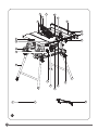 2
2
-
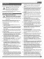 3
3
-
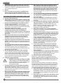 4
4
-
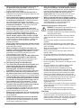 5
5
-
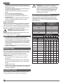 6
6
-
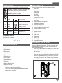 7
7
-
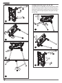 8
8
-
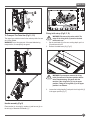 9
9
-
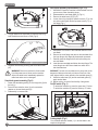 10
10
-
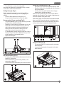 11
11
-
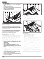 12
12
-
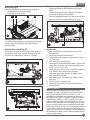 13
13
-
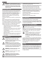 14
14
-
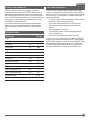 15
15
-
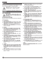 16
16
-
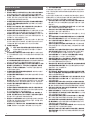 17
17
-
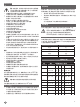 18
18
-
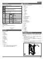 19
19
-
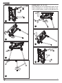 20
20
-
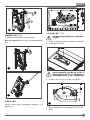 21
21
-
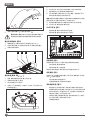 22
22
-
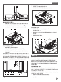 23
23
-
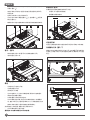 24
24
-
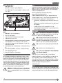 25
25
-
 26
26
-
 27
27
-
 28
28
-
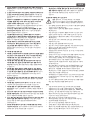 29
29
-
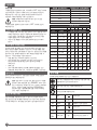 30
30
-
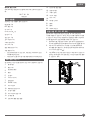 31
31
-
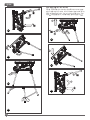 32
32
-
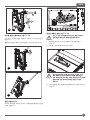 33
33
-
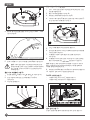 34
34
-
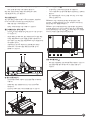 35
35
-
 36
36
-
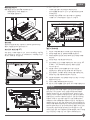 37
37
-
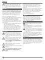 38
38
-
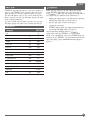 39
39


