
DWS713
Final Page Size: 210 x 297mm

English 5
简体中文 13
한국어 20

1
Fig. B
图
B
그림
B
Fig. C
图
C
그림
C
Fig. A
图
A
그림
A
17
XXXX XX XX
13
9
1
2
13
12
10
3
8
7 5
4
9
13
17
11
3
16
10
3
3
4
6
8
1
2
14
12
15
15
18
18
19
19
20
35

2
Fig. D
图
D
그림
D
Fig. E
图
E
그림
E
Fig. F
图
F
그림
F
Fig. G
图
G
그림
G
Fig. H
图
H
그림
H
Fig. I
图
I
그림
I
Fig. J
图
J
그림
J
Fig. K
图
K
그림
K
4
21
16
22
24
25
26
27
7
23
11
28
30
31
29
14
37

3
Fig. L
图
L
그림
L
Fig. M1, M2
图
M1
,
M2
그림
M1, M2
Fig. M3, M4
图
M3
,
M4
그림
M3, M4
Fig. N
图
N
그림
N
Fig. O
图
O
그림
O
Fig. P
图
P
그림
P
Fig. Q
图
Q
그림
Q
FIg. R
图
R
그림
R
32
1
33
34
12
A B
A
38
39
40

4
Fig. U
图
U
그림
U
Fig. V
图
V
그림
V
Fig. Y
图
Y
그림
Y
Fig. W
图
W
그림
W
Fig. X
图
X
그림
X
Fig. S
图
S
그림
S
Fig. T
图
T
그림
T
36
10
36
10
26
10
10
26

5
ENGLISH
English (original instructions)
Congratulations!
You have chosen a DeWALT tool. Years of experience, thorough product development and
innovation make DeWALT one of the most reliable partners for professional power toolusers.
Technical Data
DWS713
Voltage V 220-240
Power input W 1600
Blade diameter mm 254
Max. blade speed min
-1
5000
Max. cross-cut capacity 90° mm 155
Max. mitre capacity 45° mm 107
Max. depth of cut 90° mm 89
Max. depth of bevel cross-cut 45° mm 58
Baseboard vertically against fence
Max. Height mm 108
Max. Width mm 16
Mitre (max. positions) left 50°
right 50°
Bevel (max. positions) left 48°
right 3°
0° mitre
Resulting width at max. height 89 mm mm 89
Resulting height at max. width 155 mm mm 32
45° mitre
Resulting width at max. height 89 mm mm 61
Resulting height at max. width 107 mm mm 32
45° bevel
Resulting width at max. height 58 mm mm 89
Resulting height at max. width 155 mm mm 19
31.6° mitre, 33.9° bevel
Resulting height at max. width 133 mm mm 23
Automatic blade brake time s < 5
Weight kg 14
The vibration emission level given in this information sheet has been measured in accordance
with a standardised test given in EN62841 and may be used to compare one tool with another.
It may be used for a preliminary assessment ofexposure.
WARNING: The declared vibration emission level represents the main applications of the
tool. However if the tool is used for different applications, with different accessories or
poorly maintained, the vibration emission may differ. This may significantly increase the
exposure level over the total workingperiod.
An estimation of the level of exposure to vibration should also ta ke into account the times
when the tool is switched off or when it is running but not actually doing the job. This
may significantly reduce the exposure level over the total workingperiod.
Identify additional safety measures to protect the operator from the effects of vibration
such as: maintain the tool and the accessories, keep the hands warm, organisation of
workpatterns.
WARNING: To reduce the risk of injury, read the
instructionmanual.
Definitions: Safety Guidelines
The definitions below describe the level of severity for each signal word. Please read the
manual and pay attention to thesesymbols.
DANGER: Indicates an imminently hazardous situation which, if not avoided, will result
in death or seriousinjury.
WARNING: Indicates a potentially hazardous situation which, if not avoided, could result
in death or seriousinjury.
CAUTION: Indicates a potentially hazardous situation which, if not avoided, may result
in minor or moderateinjury.
NOTICE: Indicates a practice not related to personal injury which, if not avoided, may
result in propertydamage.
Denotes risk of electricshock.
Denotes risk offire.
General Power Tool Safety Warnings
WARNING: Read all safety warnings, instructions, illustrations and specifications
provided with this power tool. Failure to follow all instructions listed below may result
in electric shock, fire and/or serious injury.
254 mm COMPOUND MITRE SAW
DWS713
SAVE ALL WARNINGS AND INSTRUCTIONS
FOR FUTURE REFERENCE
The term “power tool” in the warnings refers to your mains-operated (corded) power tool or
battery-operated (cordless) powertool.
Work Area Safety
a ) Keep work area clean and well lit. Cluttered or dark areas inviteaccidents.
b ) Do not operate power tools in explosive atmospheres, such as in the presence of
flammable liquids, gases or dust. Power tools create sparks which may ignite the dust
orfumes.
c ) Keep children and bystanders away while operating a power tool. Distractions can
cause you to losecontrol.
Electrical Safety
a ) Power tool plugs must match the outlet. Never modify the plug in any way. Do
not use any adapter plugs with earthed (grounded) power tools. Unmodified plugs
and matching outlets will reduce risk of electricshock.
b ) Avoid body contact with earthed or grounded surfaces such as pipes, radiators,
ranges and refrigerators. There is an increased risk of electric shock if your body is
earthed orgrounded.
c ) Do not expose power tools to rain or wet conditions. Water entering a power tool
will increase the risk of electricshock.
d ) Do not abuse the cord. Never use the cord for carrying, pulling or unplugging
the power tool. Keep cord away from heat, oil, sharp edges or moving parts.
Damaged or entangled cords increase the risk of electricshock.
e ) When operating a power tool outdoors, use an extension cord suitable for
outdoor use. Use of a cord suitable for outdoor use reduces the risk of electricshock.
f ) If operating a power tool in a damp location is unavoidable, use a residual
current device (RCD) protected supply. Use of an RCD reduces the risk of electricshock.
Personal Safety
a ) Stay alert, watch what you are doing and use common sense when operating a
power tool. Do not use a power tool while you are tired or under the influence of
drugs, alcohol or medication. A moment of inattention while operating power tools
may result in serious personalinjury.
b ) Use personal protective equipment. Always wear eye protection. Protective
equipment such as dust mask, non-skid safety shoes, hard hat, or hearing protection used
for appropriate conditions will reduce personalinjuries.
c ) Prevent unintentional starting. Ensure the switch is in the off-position before
connecting to power source and/or battery pack, picking up or carrying the tool.
Carrying power tools with your finger on the switch or energizing power tools that have
the switch on invitesaccidents.
d ) Remove any adjusting key or wrench before turning the power tool on. A wrench
or a key left attached to a rotating part of the power tool may result in personalinjury.
e ) Do not overreach. Keep proper footing and balance at all times. This enables better
control of the power tool in unexpectedsituations.
f ) Dress properly. Do not wear loose clothing or jewelry. Keep your hair, clothing
and gloves away from moving parts. Loose clothes, jewelry or long hair can be caught
in movingparts.
g ) If devices are provided for the connection of dust extraction and collection
facilities, ensure these are connected and properly used. Use of dust collection can
reduce dust-relatedhazards.
h ) Do not let familiarity gained from frequent use of tools allow you to become
complacent and ignore tool safety principles. A careless action can cause severe
injury within a fraction of asecond.
Power Tool Use and Care
a ) Do not force the power tool. Use the correct power tool for your application. The
correct power tool will do the job better and safer at the rate for which it wasdesigned.
b ) Do not use the power tool if the switch does not turn it on and off. Any power tool
that cannot be controlled with the switch is dangerous and must berepaired.
c ) Disconnect the plug from the power source and/or the battery pack, if
detachable, from the power tool before making any adjustments, changing
accessories, or storing power tools. Such preventive safety measures reduce the risk of
starting the power toolaccidentally.
d ) Store idle power tools out of the reach of children and do not allow persons
unfamiliar with the power tool or these instructions to operate the power tool.
Power tools are dangerous in the hands of untrainedusers.
e ) Maintain power tools. Check for misalignment or binding of moving parts,
breakage of parts and any other condition that may affect the power tool’s
operation. If damaged, have the power tool repaired before use. Many accidents
are caused by poorly maintained powertools.
f ) Keep cutting tools sharp and clean. Properly maintained cutting tools with sharp
cutting edges are less likely to bind and are easier tocontrol.
g ) Use the power tool, accessories and tool bits, etc. in accordance with these
instructions, taking into account the working conditions and the work to be
performed. Use of the power tool for operations different from those intended could
result in a hazardoussituation.

6
ENGLISH
h ) Keep handles and grasping surfaces dry, clean and free from oil and grease.
Slippery handles and grasping surfaces do not allow for safe handling and control of the
tool in unexpectedsituations.
Service
a ) Have your power tool serviced by a qualified repair person using only identical
replacement parts. This will ensure that the safety of the power tool ismaintained.
Safety Instructions for Mitre Saws
a ) Mitre saws are intended to cut wood or wood-like products, they cannot be used
with abrasive cut-off wheels for cutting ferrous material such as bars, rods,
studs, etc. Abrasive dust causes moving parts such as the lower guard to jam. Sparks
from abrasive cutting will burn the lower guard, the kerf insert and other plasticparts.
b ) Use clamps to support the workpiece whenever possible. If supporting the
workpiece by hand, you must always keep your hand at least 100mm from either
side of the saw blade. Do not use this saw to cut pieces that are too small to be
securely clamped or held by hand. If your hand is placed too close to the saw blade,
there is an increased risk of injury from bladecontact.
c ) The workpiece must be stationary and clamped or held against both the fence
and the table. Do not feed the workpiece into the blade or cut “freehand” in any
way. Unrestrained or moving workpieces could be thrown at high speeds, causinginjury.
d ) Push the saw through the workpiece. Do not pull the saw through the workpiece.
To make a cut, raise the saw head and pull it out over the workpiece without
cutting, start the motor, press the saw head down and push the saw through the
workpiece. Cutting on the pull stroke is likely to cause the saw blade to climb on top of
the workpiece and violently throw the blade assembly towards theoperator.
e ) Never cross your hand over the intended line of cutting either in front or behind
the saw blade. Supporting the workpiece “cross handed” i.e. holding the workpiece to
the right of the saw blade with your left hand or vice versa is verydangerous.
f ) Do not reach behind the fence with either hand closer than 100mm from either
side of the saw blade, to remove wood scraps, or for any other reason while the
blade is spinning. The proximity of the spinning saw blade to your hand may not be
obvious and you may be seriouslyinjured.
g ) Inspect your workpiece before cutting. If the workpiece is bowed or warped,
clamp it with the outside bowed face toward the fence. Always make certain that
there is no gap between the workpiece, fence and table along the line of the cut.
Bent or warped workpieces can twist or shift and may cause binding on the spinning saw
blade while cutting. There should be no nails or foreign objects in theworkpiece.
h ) Do not use the saw until the table is clear of all tools, wood scraps, etc., except
for the workpiece. Small debris or loose pieces of wood or other objects that contact the
revolving blade can be thrown with highspeed.
i ) Cut only one workpiece at a time. Stacked multiple workpieces cannot be adequately
clamped or braced and may bind on the blade or shift duringcutting.
j ) Ensure the mitre saw is mounted or placed on a level, firm work surface before
use. A level and firm work surface reduces the risk of the mitre saw becomingunstable.
k ) Plan your work. Every time you change the bevel or mitre angle setting, make
sure the adjustable fence is set correctly to support the workpiece and will not
interfere with the blade or the guarding system. Without turning the tool “ON” and
with no workpiece on the table, move the saw blade through a complete simulated cut to
assure there will be no interference or danger of cutting thefence.
l ) Provide adequate support such as table extensions, saw horses, etc. for a
workpiece that is wider or longer than the table top. Workpieces longer or wider
than the mitre saw table can tip if not securely supported. If the cut-off piece or workpiece
tips, it can lift the lower guard or be thrown by the spinningblade.
m ) Do not use another person as a substitute for a table extension or as additional
support. Unstable support for the workpiece can cause the blade to bind or the
workpiece to shift during the cutting operation pulling you and the helper into the
spinningblade.
n ) The cut-off piece must not be jammed or pressed by any means against the
spinning saw blade. If confined, i.e. using length stops, the cut-off piece could get
wedged against the blade and thrownviolently.
o ) Always use a clamp or a fixture designed to properly support round material
such as rods or tubing. Rods have a tendency to roll while being cut, causing the blade
to “bite” and pull the work with your hand into theblade.
p ) Let the blade reach full speed before contacting the workpiece. This will reduce the
risk of the workpiece beingthrown.
q ) If the workpiece or blade becomes jammed, turn the mitre saw off. Wait for
all moving parts to stop and disconnect the plug from the power source and/
or remove the battery pack. Then work to free the jammed material. Continued
sawing with a jammed workpiece could cause loss of control or damage to the mitresaw.
r ) After finishing the cut, release the switch, hold the saw head down and wait for
the blade to stop before removing the cut-off piece. Reaching with your hand near
the coasting blade isdangerous.
s ) Hold the handle firmly when making an incomplete cut or when releasing the
switch before the saw head is completely in the down position. The braking action
of the saw may cause the saw head to be suddenly pulled downward, causing a risk
ofinjury.
Additional Safety Rules for Mitre Saws
WARNING: Do not connect to the mains power supply into the unit until complete
instructions are read andunderstood.
• DO NOT OPERATE THIS MACHINE until it is completely assembled and installed according
to the instructions. A machine incorrectly assembled can cause seriousinjury.
• OBTAIN ADVICE from your supervisor, instructor, or another qualified person if you are not
thoroughly familiar with the operation of this machine. Knowledge issafety.
• MAKE CERTAIN the blade rotates in the correct direction. The teeth on the blade should point
in the direction of rotation as marked on thesaw.
• TIGHTEN ALL CLAMP HANDLES, knobs and levers prior to operation. Loose clamps can
cause parts or the workpiece to be thrown at highspeeds.
• BE SURE all blade and blade clamps are clean, recessed sides of blade clamps are against
blade and arbour screw is tightened securely. Loose or improper blade clamping may result in
damage to the saw and possible personalinjury.
• DO NOT OPERATE ON ANYTHING OTHER THAN THE DESIGNATED VOLTAGE for the
saw. Overheating, damage to the tool and personal injury mayoccur.
• DO NOT WEDGE ANYTHING AGAINST THE FAN to hold the motor shaft. Damage to tool
and possible personal injury mayoccur.
• NEVER CUT METALS or masonry. Either of these can cause the carbide tips to fly off the blade
at high speeds causing seriousinjury.
• NEVER HAVE ANY PART OF YOUR BODY IN LINE WITH THE PATH OF THE SAW BLADE.
Personal injury willoccur.
• NEVER APPLY BLADE LUBRICANT TO A RUNNING BLADE. Applying lubricant could cause
your hand to move into the blade resulting in seriousinjury.
• DO NOT place either hand in the blade area when the saw is connected to the power source.
Inadvertent blade activation may result in seriousinjury.
• NEVER REACH AROUND OR BEHIND THE SAW BLADE. A blade can cause seriousinjury.
• DO NOT REACH UNDERNEATH THE SAW unless it is unplugged and turned off. Contact
with saw blade may cause personalinjury.
• SECURE THE MACHINE TO A STABLE SUPPORTING SURFACE. Vibration can possibly
cause the machine to slide, walk, or tip over, causing seriousinjury.
• USE ONLY CROSSCUT SAW BLADES recommended for mitre saws. For best results, do not
use carbide tipped blades with hook angles in excess of 7 degrees. Do not use blades with
deep gullets. These can deflect and contact the guard, and can cause damage to the machine
and/or seriousinjury.
• USE ONLY BLADES OF THE CORRECT SIZE AND TYPE specified for this tool to prevent
damage to the machine and/or serious injury (complying with EN847-1).
• INSPECT BLADE FOR CRACKS or other damage prior to operation. A cracked or damaged
blade can come apart and pieces can be thrown at high speeds, causing serious injury.
Replace cracked or damaged blades immediately. Observe the maximum speed marked on
the sawblade.
• CLEAN THE BLADE AND BLADE CLAMPS prior to operation. Cleaning the blade and blade
clamps allows you to check for any damage to the blade or blade clamps. A cracked or
damaged blade or blade clamp can come apart and pieces can be thrown at high speeds,
causing seriousinjury.
• DO NOT USE WARPED BLADES. Check to see if the blade runs true and is free from vibration.
A vibrating blade can cause damage to the machine and/or seriousinjury.
• DO NOT use lubricants or cleaners (particularly spray or aerosol) in the vicinity of the plastic
guard. The polycarbonate material used in the guard is subject to attack by certainchemicals.
• KEEP GUARD IN PLACE and in workingorder.
• ALWAYS USE THE KERF PLATE AND REPLACE THIS PLATE WHEN DAMAGED. Small chip
accumulation under the saw may interfere with the saw blade or may cause instability of
workpiece whencutting.
• USE ONLY BLADE CLAMPS SPECIFIED FOR THIS TOOL to prevent damage to the machine
and/or seriousinjury.
• MAKE SURE to use the correct saw blade for the material to becut.
• CLEAN THE MOTOR AIR SLOTS of chips and sawdust. Clogged motor air slots can cause the
machine to overheat, damaging the machine and possibly causing a short which could cause
seriousinjury.
• NEVER LOCK THE SWITCH IN THE “ON” POSITION. Severe personal injury mayresult.
• NEVER STAND ON TOOL. Serious injury could occur if the tool is tipped or if the cutting tool
is unintentionallycontacted.
WARNING: Cutting plastics, sap coated wood, and other materials may cause melted
material to accumulate on the blade tips and the body of the saw blade, increasing the
risk of blade overheating and binding whilecutting.
WARNING: Always wear proper personal hearing protection. Under some
conditions and duration of use, noise from this product may contribute to hearing loss. Be
aware of the following factors influencing exposure to noise:
• Use saw blades designed to reduce the emitted noise,
• Use only well sharpened saw blades, and
• Use specifically designed noise-reduction sawblades.
WARNING: ALWAYS use safety glasses. Everyday eyeglasses are NOT safety glasses. Also
use face or dust mask if cutting operation isdusty.
WARNING: Use of this tool can generate and/or disperse dust, which may cause serious
and permanent respiratory or otherinjury.
WARNING: Some dust created by power sanding, sawing, grinding, drilling, and other
construction activities contains chemicals known to cause cancer, birth defects or other
reproductive harm. Some examples of these chemicals are:
• lead from lead-based paints,
• crystalline silica from bricks and cement and other masonry products, and

7
ENGLISH
• arsenic and chromium from chemically-treatedlumber.
Your risk from these exposures varies, depending on how often you do this type of work. To reduce
your exposure to these chemicals: work in a well ventilated area, and work with approved safety
equipment, such as those dust masks that are specially designed to filter out microscopicparticles.
• Avoid prolonged contact with dust from power sanding, sawing, grinding, drilling,
and other construction activities. Wear protective clothing and wash exposed areas with
soap and water. Allowing dust to get into your mouth, eyes, or lay on the skin may promote
absorption of harmfulchemicals.
WARNING: Use of this tool can generate and/or disperse dust, which may cause serious
and permanent respiratory or other injury. Always use approved respiratory protection
appropriate for the dustexposure.
Residual Risks
The following risks are inherent to the use of saws:
• Injuries caused by touching the rotatingparts.
In spite of the application of the relevant safety regulations and the implementation of safety
devices, certain residual risks cannot be avoided. These are:
• Impairment ofhearing.
• Risk of accidents caused by the uncovered parts of the rotating sawblade.
• Risk of injury when changing theblade.
• Risk of squeezing fingers when opening theguards.
• Health hazards caused by breathing dust developed when sawing wood, especially oak,
beech andMDF.
The following factors increase the risk of breathing problems:
• No dust extractor connected when sawingwood.
• Insufficient dust extraction caused by uncleaned exhaustfilters.
Electrical Safety
The electric motor has been designed for one voltage only. Always check that the power
supply corresponds to the voltage on the ratingplate.
Your DeWALT tool is double insulated in accordance
with IEC62841; therefore no earth wire isrequired.
WARNING: We recommend the use of a residual current device with a residual current
rating of 30mA orless.
WARNING: 115 V units have to be operated via a fail-safe isolating transformer with an
earth screen between the primary and secondarywinding.
If the supply cord is damaged, it must be replaced by a specially prepared cord available
through the DeWALT serviceorganisation.
Using an Extension Cable
If an extension cable is required, use an approved 3–core extension cable suitable for the
power input of this tool (see Technical Data).The minimum conductor size is 1.5 mm
2
; the
maximum length is 30m.
When using a cable reel, always unwind the cablecompletely.
Package Contents
The package contains:
1 Mitre saw
1 6 mm hex wrench
1 Saw blade
1 Dustbag
1 Material clamp
1 Instruction manual
• Check for damage to the tool, parts or accessories which may have occurred duringtransport.
• Take the time to thoroughly read and understand this manual prior tooperation.
Markings on Tool
The following pictograms are shown on the tool:
Read instruction manual beforeuse.
Wear earprotection.
Wear eyeprotection.
Keep hands away fromblade.
Visible radiation. Do not stare intolight.
Date Code Position (Fig. A)
The date code
35
, which also includes the year of manufacture, is printed into thehousing.
Example:
2018 XX XX
Year of Manufacture
Description (Fig. A)
WARNING: Never modify the power tool or any part of it. Damage or personal injury
couldresult.
1
Trigger switch
2
Operating handle
3
Mounting holes
4
Lower guard
5
Mitre lock knob
6
Mitre detent latch
7
Mitre scale
8
Mitre scale screws
9
Hand indentations
10
Sliding fence
11
Bevel lock knob
12
Dust port
13
Carrying handle
14
Fence lock knob
15
Clamp mounting holes
16
6 mm hex wrench
17
Head lock knob
18
Base fence
19
Vertical material clamp
20
Mitre detent override
Intended Use
Your DeWALT DWS713 compound mitre saw has been designed for professional wood
cuttingapplications. When using the appropriate saw blades, sawing aluminium profiles and
plastic is alsopossible.
DO NOT use under wet conditions or in the presence of flammable liquids orgases.
This mitre saw is a professional powertool.
DO NOT let children come into contact with the tool. Supervision is required when
inexperienced operators use thistool.
• Young children and the infirm. This appliance is not intended for use by young children
or infirm persons withoutsupervision.
• This product is not intended for use by persons (including children) suffering from
diminished physical, sensory or mental abilities; lack of experience, knowledge or skills
unless they are supervised by a person responsible for their safety. Children should never
be left alone with thisproduct.
Familiarization (Fig. A, B)
Your mitre saw is fully assembled in the carton. Open the box and lift the saw out by the
convenient carrying handle
13
, as shown in FigureB.
Place the saw on a smooth, flat surface such as a workbench or strongtable.
Examine Figure A to become familiar with the saw and its various parts. The section on
adjustments will refer to these terms and you must know what and where the partsare.
CAUTION: Pinch Hazard. To reduce the risk of injury, keep thumb underneath the handle
when pulling the handle down. The lower guard will move up as the handle is pulled
down which could cause pinching.The handle is placed close to the guard for specialcuts.
Press down lightly on the operating handle
2
and loosen the head lock knob
17
. Gently
release the downward pressure and allow the arm to rise to its full height. Use the lock down
pin when carrying the saw from one place to another. Always use the carrying handle
13
to
transport the saw or the hand indentations
9
shown in FigureA.
Bench Mounting (Fig. A)
Mounting holes
3
are provided in all four feet to facilitate bench mounting, as shown in
FigureA. (Two different sized holes are provided to accommodate different sizes of screws.
Use either hole, it is not necessary to use both.) Always mount your saw firmly to prevent
movement. To enhance the tool’s portability, it can be mounted to a piece of 12.7 mm or
thicker plywood which can then be clamped to your work support or moved to other job sites
andreclamped.
NOTE: If you elect to mount your saw to a piece of plywood, make sure that the mounting
screws don’t protrude from the bottom of the wood. The plywood must sit flush on the work
support. When clamping the saw to any work surface, clamp only on the clamping bosses
where the mounting screw holes are located. Clamping at any other point will surely interfere
with the proper operation of thesaw.
CAUTION: To prevent binding and inaccuracy, be sure the mounting surface is not
warped or otherwise uneven. If the saw rocks on the surface place a thin piece of material
under one saw foot until the saw sits firmly on the mountingsurface.
Transporting the Saw (Fig.A, C)
WARNING: To reduce the risk of serious personal injury, turn off the tool and
disconnect it from the power source before attempting to move it, change
accessories or make anyadjustments.
WARNING: To reduce the risk of serious personal injury, ALWAYS lock the mitre lock knob,
bevel lock handle, head lock knob, and fence adjustment knob before transportingsaw.
In order to conveniently carry the mitre saw from place to place, a carrying handle
13
has
been included on the top of the saw arm and hand indentations
9
in the base, as shown in
FigureA. To transport the saw, lower the arm and tighten the head lock knob
17
shown in
FigureC.
ASSEMBLY AND ADJUSTMENTS
WARNING: To reduce the risk of serious personal injury, turn tool off and
disconnect tool from power source before making any adjustments or removing/
installing attachments or accessories. Be sure the trigger switch is in the OFF position.
An accidental start-up can causeinjury.

8
ENGLISH
Changing or Installing a New Saw Blade (Fig.D–F)
WARNING: To reduce the risk of serious personal injury, turn off the tool and
disconnect it from the power source before attempting to move it, change
accessories or make anyadjustments.
WARNING: When mounting the saw blade, wear protective gloves. Danger of
injury when touching the sawblade.
CAUTION:
• Never depress the spindle lock button while the blade is under power orcoasting.
• Do not cut ferrous metal (containing iron or steel) or masonry or fiber cement product
with this mitresaw.
Removing the Blade
1. Unplug thesaw.
2. Raise the arm to the upper position and raise the lower guard
4
as far aspossible.
3. Loosen, but do not remove guard bracket screw
21
until the bracket can be raised far
enough to access the blade screw. Lower guard will remain raised due to the position of
the guard bracketscrew.
4. Depress the spindle lock button
22
while carefully rotating the saw blade by hand until
the lockengages.
5. Keeping the button depressed, use the other hand and the 6 mm hex wrench
16
provided to loosen the blade screw
24
. (Turn clockwise, left-hand threads.)
6. Remove the blade screw
24
, outer blade clamp
25
, and blade
26
. The inner blade
clamp
27
, and if used, the 25.4 mm blade adapter
37
, may be left on thespindle.
NOTE: For blades with a blade hole of 15.88 mm, the 25.4 mm blade adapter is notused.
Installing a Blade
1. Unplug thesaw.
2. With the arm raised, the lower guard held open and the guard bracket, place the
blade
26
on the spindle against the inner blade clamp
27
with the teeth at the bottom
of the blade pointing toward the back of thesaw.
3. Assemble the outer blade clamp
25
onto thespindle.
4. Install the blade screw
24
and, engaging the spindle lock, tighten the screw firmly with
the 6 mm hex wrench provided. (Turn counterclockwise, left-hand threads.)
5. Return the guard bracket to its original position and firmly tighten the guard bracket
screw
21
to hold bracket inplace.
WARNING:
• The guard bracket must be returned to its original position and the screw
tightened before activating thesaw.
• Failure to do so may allow the guard to contact the spinning saw blade
resulting in damage to the saw and severe personalinjury.
Mitre Scale Adjustment (Fig.A, G)
Place a square against the saw’s fence and blade. (Do not touch the tips of the blade teeth
with the square. To do so will cause an inaccurate measurement.) Unlock mitre lock knob
5
and swing the mitre arm until the mitre detent locks it at the 0˚ mitre position. Do not lock
mitre lock knob. If the saw blade is not exactly perpendicular to the base fence
18
, loosen
the three mitre scale screws
8
that hold the mitre scale
7
to the base and move the scale/
mitre arm assembly left or right until the blade is perpendicular to the fence, as measured with
the square. Retighten the three screws. Pay no attention to the reading of the mitre pointer at
thispoint.
Mitre Pointer Adjustment (Fig.A, H)
Unlock mitre lock knob
5
and squeeze the mitre detent latch
6
to move the mitre arm to
the zero position. Unlock the mitre lock knob to allow the mitre detent to snap into place as
you rotate the mitre arm toward zero. Observe the pointer
23
and mitre scale
7
through the
viewing opening shown in FigureH. If the pointer does not indicate exactly zero, loosen the
pointer screw, adjust the pointer to 0˚ andretighten.
Bevel Square to Table (Fig. I, J)
To align the blade square to the rotary table, lock the arm in the down position. Place a square
against the blade taking care to not have the square on top of a tooth. Loosen the bevel lock
knob
11
so that you can move the bevel arm. Move the bevel arm as necessary so that the
blade is at 0° bevel to the table. If the bevel arm needs adjustment, locate the right side bevel
stop as shown in FigureJ, and adjust the stop screw
28
asnecessary.
Bevel Pointer (Fig.J)
If the bevel pointer
30
does not indicate zero, loosen the screw
31
that holds it in place and
move the pointer asnecessary.
SUGGESTION: For accuracy, set the top edge so that it aligns withzero.
Bevel Stop (Fig.A, J)
To set the 45° bevel stop, first loosen the left side fence lock knob
14
and slide the sliding
fence
10
as far as it will go to the left. Move the arm to the left until it stops on the left
side bevel stop screw
29
. If the bevel pointer does not indicate exactly 45°, turn the screw
downwards. Move the arm to the left and tighten the bevel lock knob
11
firmly when the
bevel pointer indicates exactly 45°. Adjust the left side bevel stop screw
29
upwards until it
firmly touches the bevelstop.
To achieve 3° right bevel or 48° left bevel, the stop screws must be adjusted to allow the arm
to move to the desired location. The bevel stops will need readjustment to the zero and 45°
positions after cuts aremade.
Fence Adjustment (Fig.K)
WARNING: To reduce the risk of serious personal injury, turn off the tool and
disconnect it from the power source before attempting to move it, change
accessories or make anyadjustments.
To bevel UP TO 48° left, the left side of the fence can be adjusted to the left to provide
clearance. To adjust the fence, loosen the fence lock knob
14
and slide the fence to the left.
Make a dry run with the saw turned off and check for clearance. Adjust the fence to be as close
to the blade as practical to provide maximum workpiece support, without interfering with
arm up and down movement. Tighten the fence clamping knob securely. When the bevel
operations are complete, don’t forget to relocate the fence to theright.
Guard Actuation and Visibility (Fig.L)
CAUTION: Pinch Hazard. To reduce the risk of injury, keep thumb underneath the handle
when pulling the handle down. The lower guard will move up as the handle is pulled
down which could causepinching.
The blade guard on your saw has been designed to automatically raise when the arm is
brought down and to lower over the blade when the arm israised.
The guard can be raised by hand when installing or removing saw blades or for inspection of
the saw. NEVER RAISE THE BLADE GUARD MANUALLY UNLESS THE SAW IS TURNEDOFF.
NOTE: Certain special cuts will require that you manually raise the guard. Refer to Cutting
Large Material under SpecialCuts.
The front section of the guard is louvered for visibility while cutting. Although the louvers
dramatically reduce flying debris, there are openings in the guard and safety glasses should be
worn at all times when viewing through thelouvers.
Automatic Electric Brake
Your saw is equipped with an automatic electric blade brake which stops the saw blade within
5seconds of trigger release. This is notadjustable.
On occasion, there may be a delay after trigger release to brake engagement. On rare
occasions, the brake may not engage at all and the blade will coast to astop.
If a delay or “skipping” occurs, turn the saw on and off 4 or 5 times. If the condition persists,
have the tool serviced by an authorised DeWALT servicecentre.
Always be sure the blade has stopped before removing it from the kerf plate. The brake
is not a substitute for guards or for ensuring your own safety by giving the saw your
completeattention.
Controls
Your compound mitre saw has several main controls, which will be discussed briefly here. For
more information on these controls, see the respective sections later in themanual.
Mitre Control (Fig.A)
The mitre lock knob
5
and mitre detent latch
6
allow you to mitre your saw 50° left and right.
To mitre the saw, unlock mitre lock knob
5
by rotating the knob counterclockwise, squeeze
the mitre detent latch
6
and set the mitre angle desired on the mitre scale. Lock mitre lock
knob by rotating clockwise until tight. Override the mitre detent latch by unlocking the mitre
lock knob and pushing the mitre detent override
20
downward. To exit the override, push the
mitre detent override switchupward.
Bevel Lock (Fig.J)
The bevel lock knob
11
allows you to bevel the saw 48° left and 3° to the right. To loosen the
handle and adjust the bevel setting, turn the handle counter clock wise, the saw head bevels
easily to the left. To tighten, turn the handle clockwise. Bevel degree markings are on the
bottom front of the saw arm (Fig.H).
Head Downlock Pin (Fig.A)
To lock the saw head in the down position, push the head down, rotate head lock knob
17
90° and the spring loaded pin will lock in and release the saw head. This will hold the saw
head safely down for moving the saw from place to place. To release, pull out the head lock
knob and rotate90°.
OPERATION
Instructions for Use
WARNING: Always observe the safety instructions and applicableregulations.
WARNING: To reduce the risk of serious personal injury, turn tool off and
disconnect tool from power source before making any adjustments or removing/
installing attachments or accessories. Be sure the trigger switch is in the OFF position.
An accidental start-up can causeinjury.
Body and Hand Position (Fig. M1–M4)
WARNING: To reduce the risk of serious personal injury, ALWAYS use proper hand
position asshown.
WARNING: To reduce the risk of serious personal injury, ALWAYS hold securely in
anticipation of a suddenreaction.
Proper positioning of your body and hands when operating the mitre saw will make cutting
easier, more accurate and safer. Never place hands near cutting area. Place hands no closer
than 152 mm from the blade. Hold the workpiece tightly to the table and the fence when
cutting. Keep hands in position until the trigger has been released and the blade has
completely stopped. ALWAYS MAKE DRY RUNS (UNPOWERED) BEFORE FINISH CUTS SO THAT
YOU CAN CHECK THE PATH OF THE BLADE. DO NOT CROSS ARMS, AS SHOWN IN FIGUREM3.

9
ENGLISH
Keep both feet firmly on the floor and maintain proper balance. As you move the mitre arm
left and right, follow it and stand slightly to the side of the saw blade. Sight through the guard
louvers when following a pencilline.
Trigger Switch (Fig.N)
To turn the saw on, push the lock-off lever
32
to the left, then depress the trigger switch
1
.
The saw will run while the switch is depressed. Allow the blade to spin up to full operating
speed before making the cut. To turn the saw off, release the switch. Allow the blade to stop
before raising the saw head. There is no provision for locking the switch on. A hole
33
is
provided in the trigger for insertion of a padlock to lock the switchoff.
Always be sure the blade has stopped before removing it from thekerf.
Dust Extraction (Fig.O)
WARNING: To reduce the risk of serious personal injury, turn tool off and
disconnect tool from power source before transporting, making any adjustments
or removing/installing attachments or accessories. An accidental start-up can
causeinjury.
WARNING: Certain dust, such as oak or beech dust, is considered carcinogenic, especially
in connection with wood-treatmentadditives.
• Always use dustextraction.
• Provide for good ventilation of the workspace.
• It is recommended to wear an appropriaterespirator.
CAUTION: Never operate this saw unless the dust bag or DeWALT dust extractor is
in place. Wood dust may create a breathinghazard.
CAUTION: Check and clean the dust bag each time afterusing.
WARNING: When sawing aluminium, remove the dust bag to avoid the risk offire.
Your miter saw has a built-in dust port
12
that allows connection to either the supplied dust
bag
34
, 35mm nozzles or direct attachment to the DeWALT AirLock(DWV9000-XJ).
Observe the relevant regulations in your country for the materials to beworked.
To Attach the Dust Bag
1. Fit the dust bag
34
to the dust port
12
as shown in FigureO.
To Empty the Dust Bag
1. Remove dust bag
34
from the saw and gently shake or tap the dust bag toempty.
2. Reattach the dust bag back onto the dust port
12
.
You may notice that all the dust will not come free from the bag. This will not affect cutting
performance but will reduce the saw's dust collection efficiency. To restore your saw's dust
collection efficiency, depress the spring inside the dust bag when you are emptying it and tap
it on the side of the trash can or dustreceptacle.
External Dust Extraction (Fig. O)
When vacuuming dry dust that is especially detrimental to health or carcinogenic, use a
special dust Class M vacuumcleaner.
Connecting to an AirLock Compatable Dust Extractor (Fig.O)
The dust extractor port
12
on your mitre saw is compatable with the DeWALT AirLock
connection system. The AirLock allows for a fast, secure connection between the dust
extractor hose
38
and the mitresaw.
1. Ensure the collar on the AirLock connector
39
is in the unlock position. (Refer to FigureO.)
Align notches
40
on collar and AirLock connector as shown for unlock and lockpositions.
2. Push the AirLock connector onto the dust extractor port
12
.
3. Rotate the collar to the lockedposition.
NOTE: The ball bearings inside collar lock into slot and secure the connection.The mitre
saw is now securely connected to the dustextractor.
Cutting With Your Saw
NOTE: Although this saw will cut wood and many non-ferrous materials, we will limit our
discussion to the cutting of wood only. The same guidelines apply to the other materials. DO
NOT CUT FERROUS (IRON AND STEEL) MATERIALS OR MASONRY WITH THIS SAW. Do
not use any abrasiveblades.
Crosscuts (Fig. N)
Cutting of multiple pieces is not recommended but can be done safely by ensuring that each
piece is held firmly against the table and fence. A crosscut is made by cutting wood across the
grain at any angle. A straight crosscut is made with the mitre arm at the zero degree position.
Set the mitre arm at zero, hold the wood on the table and firmly against the fence. Turn on the
saw by squeezing the trigger switch shown in FigureN.
When the saw comes up to speed (about 1 second) lower the arm smoothly and slowly to cut
through the wood. Let the blade come to a full stop before raisingarm.
CAUTION: Always use a work clamp to maintain control and reduce the risk of workpiece
damage and personalinjury.
Mitre crosscuts are made with the mitre arm at some angle other than zero. This angle is
often 45° for making corners, but can be set anywhere from zero to 50° left or right. After
selecting the desired mitre angle, be sure to tighten the mitre lock knob. Make the cut as
describedabove.
To cut through an existing pencil line on a piece of wood, match the angle as close as possible.
Cut the wood a little too long and measure from the pencil line to the cut edge to determine
which direction to adjust the mitre angle and recut. This will take some practice, but it is a
commonly usedtechnique.
Bevel Cuts (Fig.A)
A bevel cut is a crosscut made with the saw blade at a bevel to the wood. In order to set the
bevel, loosen the bevel lock knob
11
and move the saw to the left as desired. (It is necessary
to move the left side of the fence to allow clearance). Once the desired bevel angle has been
set, tighten the bevel clamp knobfirmly.
Bevel angles can be set from 3° right to 48° left and can be cut with the mitre arm set between
zero and 50° right or left. Ensure the fence has been adjusted properly. When cutting left
bevel, or right mitre compound cuts, it will be necessary to remove the adjustablefence.
Quality of cut
The smoothness of any cut depends on a number of things contributing to the quality of the
cut are: material being cut, blade type, blade sharpness and rate of cut all contribute to the
quality of thecut.
When smoothest cuts are desired for molding and other precision work, a sharp (60–80 tooth
carbide) blade and a slower, even cutting rate will produce the desiredresults.
Ensure that material does not creep while cutting. Clamp it securely in place. Always let the
blade come to a full stop before raisingarm.
If small fibers of wood still split out at the rear of the workpiece, apply a piece of masking tape
on the wood where the cut will be made. Saw through the tape and carefully remove tape
when the cut isfinished.
For varied cutting applications, refer to the list of recommended saw blades for your saw and
select the one that best fits your needs. Refer to Saw Blades under Optional Accessories for
correct sawblade.
Clamping the Workpiece
WARNING: To reduce the risk of serious personal injury, turn off the tool and
disconnect it from the power source before attempting to move it, change
accessories or make anyadjustments.
WARNING: A workpiece that is clamped, balanced and secure before a cut may become
unbalanced after a cut is completed. An unbalanced load may tip the saw or anything the
saw is attached to, such as a table or workbench. When making a cut that may become
unbalanced, properly support the workpiece and ensure the saw is firmly bolted to a
stable surface. Personal injury mayoccur.
WARNING: The clamp foot must remain clamped above the base of the saw whenever
the clamp is used. Always clamp the workpiece to the base of the saw–not to any other
part of the work area. Ensure the clamp foot is not clamped on the edge of the base of
thesaw.
CAUTION: Always use a work clamp to maintain control and reduce the risk of workpiece
damage and personalinjury.
If you cannot secure the workpiece on the table and against the fence by hand, (irregular
shape, etc.) or your hand would be less than 100 mm from the blade, a clamp or other fixture
should beused.
For best results use the clamp provided with yoursaw.
Other aids such as spring clamps, bar clamps or C-clamps may be appropriate for certain sizes
and shapes of material. Use care in selecting and placing these clamps. Take time to make a
dry run before making the cut. The left fence will slide from side to side to aid inclamping.
To Install Clamp (Fig. A)
1. Insert the clamp into one of the four locations
15
on thebase.
2. Lifting up on the arm of the clamp can rapidly adjust the height, then use the fine adjust
knob to firmly clamp theworkpiece.
NOTE: Place the clamp on the opposite side of the base when beveling. ALWAYS MAKE DRY
RUNS (UNPOWERED) BEFORE FINISH CUTS TO CHECK THE PATH OF THE BLADE. ENSURE THE
CLAMP DOES NOT INTERFERE WITH THE ACTION OF THE SAW ORGUARDS.
Support for Long Pieces
WARNING: To reduce the risk of serious personal injury, turn off the tool and
disconnect it from the power source before attempting to move it, change
accessories or make anyadjustments.
ALWAYS SUPPORT LONGPIECES.
Never use another person as a substitute for a table extension; as additional support for a
workpiece that is longer or wider than the basic mitre saw table or to help feed, support or
pull theworkpiece.
For best results, use the DWX723, DE7260 or DE7033 mitre saw stand to extend the table
width of your saw. This is available from your dealer at extracost.
Support long workpieces using any convenient means such as sawhorses or similar devices to
keep the ends fromdropping.
Cutting Picture Frames, Shadow Boxes and Other Four-Sided
Projects (Fig. P)
To best understand how to make the items listed here, we suggest that you try a few simple
projects using scrap wood until you develop a “FEEL” for yoursaw.
Your saw is the perfect tool for mitreing corners like the one shown in FigureP. Sketch A in
FigureP shows a joint made by using the bevel adjustment to bevel the edges of the two
boards at 45° each to produce a 90° mitre corner. For this joint the mitre arm was locked in the
zero position and the bevel adjustment was locked at 45°. The wood was positioned with the
broad flat side against the table and the narrow edge against the fence. The cut could also be
made by mitreing right and left with the broad surface against thefence.
Cutting Trim Molding and Other Frames (Fig. P)
Sketch B in FigureP shows a joint made by setting the mitre arm at 45° to mitre the two
boards to form a 90° corner. To make this type of joint, set the bevel adjustment to zero and

10
ENGLISH
the mitre arm to 45°. Once again, position the wood with the broad flat side on the table and
the narrow edge against thefence.
The two sketches in FigureP are for four sided objectsonly.
As the number of sides changes, so do the mitre and bevel angles. The chart below gives the
proper angles for a variety of shapes. The chart assumes that all sides are of equal length. For a
shape that is not shown in the chart, use the following formula. 180° divided by the number of
sides equals the mitre or bevelangle.
EXAMPLES
No. Sides Angle Mitre or Bevel
4 45°
5 36°
6 30°
7 25.7°
8 22.5°
9 20°
10 18°
Cutting Compound Mitres (Fig. Q, R)
A compound mitre is a cut made using a mitre angle and a bevel angle at the same time.
This is the type of cut used to make frames or boxes with slanting sides like the one shown in
FigureQ.
NOTE: If the cutting angle varies from cut to cut, check that the bevel clamp knob and the
mitre lock knob are securely tightened. These knobs must be tightened after making any
changes in bevel ormitre.
The chart (Table 1) will assist you in selecting the proper bevel and mitre settings for common
compound mitre cuts. To use the chart, select the desired angle “A” (FigureR) of your
project and locate that angle on the appropriate arc in the chart. From that point follow the
chart straight down to find the correct bevel angle and straight across to find the correct
mitreangle.
Set your saw to the prescribed angles and make a few trial cuts. Practice fitting the cut pieces
together until you develop a feel for this procedure and feel comfortable withit.
EXAMPLE: To make a 4 sided box with 26° exterior angles (Angle A, FigureR), use the upper
right arc. Find 26° on the arc scale. Follow the horizontal intersecting line to either side to get
mitre angle setting on saw (42°). Likewise, follow the vertical intersecting line to the top or
bottom to get the bevel angle setting on the saw (18°). Always try cuts on a few scrap pieces
of wood to verify settings onsaw.
SET THIS BEVEL ANGLE ON SAW
SET THIS MITER ANGLE ON SAW
ANGLE OF SIDE OF BOX (ANGLE"A")
SQUARE BOX
6 SIDED BOX
8 SIDED BOX
Mitre Scale (Fig.A)
The mitre scale
7
is used when calculating angles. To calculate the proper mitre angle, divide
180° by the number of sides of the box or frame. Refer toExamples.
When Mitreing to the Right
To increase the mitre angle when mitreing to the right, move the arm to align the appropriate
vernier mark with the closest mark on the mitre scale to the right. To decrease the mitre angle
when mitreing to the right, move the arm to align the appropriate vernier mark with the
closest mark on the mitre scale to theleft.
When Mitreing to the Left
To increase the mitre angle when mitreing to the left, move the arm to align the appropriate
vernier mark with the closest mark on the mitre scale to the left. To decrease the mitre angle
when mitreing to the left, move the arm to align the appropriate vernier mark with the closest
mark on the mitre scale to theright.
Cutting Base Molding
ALWAYS MAKE A DRY RUN WITHOUT POWER BEFORE MAKING ANYCUTS.
Straight 90° Cuts (Fig. S)
Position the wood against the fence as shown in FigureS. Turn on the saw, allow the blade to
reach full speed and lower the arm smoothly through thecut.
Cutting Base Molding up to 89 mm High Vertically Against The Fence
(Fig. L, S)
Position molding as shown in FigureS.
All cuts are made with the back of the molding against the fence and bottom of the molding
against thebase.
Inside corner Outside corner
Left side
1. Mitre left 45°
2. Save left side of cut
1. Mitre right 45°
2. Save left side of cut
Right side
1. Mitre right 45°
2. Save right side of cut
1. Mitre left 45°
2. Save right side of cut
Material up to 89 mm can be cut as described above. For wider boards [up to 108 mm] several
minor concessions must bemade.
When cutting a board between 89 mm and 108 mm in width the roller on the tip of the
guard could hang up on the workpiece. If this occurs, simply place your right thumb on the
upper side of the guard and roll the guard up just enough to clear the workpiece, as shown in
FigureL. Once you have cleared the workpiece, you can release the guard and it will continue
to open as the cutprogresses.
When mitreing to the right side of a base molding wider than 89 mm standing vertically
against the fence as in FigureU, the saw can only cut through the board up to 1 inch from the
end of the board. Trying to cut more than an inch will cause the saw’s gear case to interfere
with the workpiece. If you want to cut base molding between 89 mm and 108 mm wide
vertically follow the directionsbelow.
Cutting 89 mm–108 mm Base Molding Vertically Against the Fence
(Fig. S)
• Position molding as shown in FigureS.
• All cuts made with the back of the molding against the fence.
Inside corner Outside corner
Left side*
1. Position molding with bottom of
molding against the base of the saw
2. Mitre left 45°
3. Save left side of cut
1. Position molding with bottom of
molding against the base of the saw
2. Mitre right 45°
3. Save left side of cut
Right side
1. Position molding with bottom of the
molding resting on the base of the saw
2. Mitre right 45°
3. Save right side of cut
1. Position molding with bottom of the
molding against the base of the saw
2. Mitre left 45°
3. Save right side of cut
* NOTE: If the cut must be made somewhere other than 1" from the end of the molding: cut off
the molding at 90° approx. 25.4 mm longer than your final length then make the mitre cut as
described above.
Another method of making the cut is to make a zero degree mitre, 45° bevel cut. Your saw can
cut a bevel 158 mmwide.
Cutting Base Molding Laying Flat and Using the Bevel Feature
• All cuts made with the saw set at 45° bevel and 0mitre.
• All cuts made with back of molding laying flat on thesaw.
• Move the left side fence out of the path of the blade before attempting any of the
followingcuts.
Inside corner Outside corner
Left side
1. Position molding with top of molding
against the fence
2. Save left side of cut
1. Position molding with bottom of the
molding against the fence
2. Save left side of cut
Right side
1. Position molding with bottom of the
molding against the fence
2. Save right side of cut
1. Position molding with top of molding
against the fence
2. Save right side of cut
Cutting Crown Molding
Your mitre saw is better suited to the task of cutting crown molding than any tool made. In
order to fit properly, crown molding must be compound mitreed with extremeaccuracy.
The two flat surfaces on a given piece of crown molding are at angles that, when added
together, equal exactly 90°. Most, but not all, crown molding has a top rear angle (the section
that fits flat against the ceiling) of 52° and a bottom rear angle (the part that fits flat against the
wall) of 38°.
Your mitre saw has special pre-set mitre detent points at 31.62° left and right for cutting crown
molding at the proper angle. There is also a mark on the Bevel scale at 33.85°.
The Bevel Setting/Type of Cut chart gives the proper settings for cutting crown molding. (The
numbers for the mitre and bevel settings are very precise and are not easy to accurately set
on your saw.) Since most rooms do not have angles of precisely 90°, you will have to fine tune
your settingsanyway.
PRETESTING WITH SCRAP MATERIAL IS EX TREME LY IMPORTANT!
For Cutting Crown Molding Laying Flat and Using the Compound
Features (Fig. T)
1. Move the sliding fence
10
out of the path of the blade before attempting any of the
followingcuts.

11
ENGLISH
2. Molding laying with broad back surface down flat on saw table
36
(Fig.T).
BEVEL SETTING TYPE OF CUT
33.9°
LEFT SIDE, INSIDE CORNER
1. Top of molding against fence
2. Mitre table set right 31.6°
3. Save left end of cut
33.9°
RIGHT SIDE, INSIDE CORNER
1. Bottom of molding against fence
2. Mitre table set left 31.6°
3. Save left end of cut
33.9°
LEFT SIDE, OUTSIDE CORNER
1. Bottom of molding against fence
2. Mitre table set left 31.6°
3. Save right end of cut
33.9°
RIGHT SIDE, OUTSIDE CORNER
1. Top of molding against fence
2. Mitre table set right 31.6°
3. Save right end of cut
When setting bevel and mitre angles for all compound mitres, remember that:
The angles presented for crown moldings are very precise and difficult to set exactly. Since
they can easily shift slightly and very few rooms have exactly square corners, all settings should
be tested on scrapmolding.
PRETESTING WITH SCRAP MATERIAL IS EXTREME LY IMPORTANT!
Alternative Method for Cutting Crown Molding (Fig. U)
Place the molding on the table at an angle between the sliding fence
10
and the saw
table
36
, as shown in FigureU. Use of the crown molding fence accessory (DW7084) is highly
recommended because of its degree of accuracy and convenience. The crown molding fence
accessory is available at extra cost from your localdealer.
The advantage to cutting crown molding using this method is that no bevel cut is required.
Minute changes in the mitre angle can be made without affecting the bevel angle. This way,
when corners other than 90° are encountered, the saw can be quickly and easily adjusted for
them. Use the crown molding fence accessory (DW7084) to maintain the angle at which the
molding will be on thewall.
Instructions for Cutting Crown Molding Angled Between the Fence and
Base of the Saw for All Cuts (Fig. U)
1. Angle the molding so the bottom of the molding (part which goes against the wall when
installed) is against the fence and the top of the molding is resting on the base of the saw,
as shown in FigureU.
2. The angled “flats” on the back of the molding must rest squarely on the fence and base of
thesaw.
Inside corner Outside corner
Left side
1. Mitre right 45°
2. Save right side of cut
1. Mitre left 45°
2. Save right side of cut
Right side
1. Mitre left 45°
2. Save left side of cut
1. Mitre right 45°
2. Save left side of cut
Special Cuts
NEVER MAKE ANY CUT UNLESS THE MATERIAL IS SECURED ON THE TABLE AND AGAINST
THEFENCE.
Aluminum Cutting (Fig, A, V, W)
ALWAYS USE THE APPROPRIATE SAW BLADE MADE ESPECIALLY FOR CUTTING ALUMINUM.
These are available at your local DeWALT retailer or DeWALT service centre. Certain workpieces,
due to their size, shape or surface finish, may require the use of a clamp or fixture to prevent
movement during the cut. Position the material so that you will be cutting the thinnest cross
section, as shown in FigureV. Figure W illustrates the wrong way to cut these extrusions. Use
a stick wax cutting lubricant when cutting aluminum. Apply the stick wax directly to the saw
blade
26
before cutting. Never apply stick wax to a movingblade.
The wax, available at most hardware stores and industrial mill supply houses, provides proper
lubrication and keeps chips from adhering to theblade.
Be sure to properly secure workpiece. Refer to Saw Blades under Optional Accessories for
correct sawblade.
Bowed Material (Fig. X, Y)
When cutting bowed material always position it as shown in Figure X and never like that
shown in Figure Y. Positioning the material incorrectly will cause it to pinch the blade near the
completion of thecut.
Cutting Plastic Pipe or Other Round Material
Plastic pipe can be easily cut with your saw. It should be cut just like wood and CLAMPED
OR HELD FIRMLY TO THE FENCE TO KEEP IT FROM ROLLING. This is extremely important
when making anglecuts.
Cutting Large Material (Fig. L)
Occasionally you will encounter a piece of wood a little too large to fit beneath the blade
guard. A little extra height can be gained by rolling the guard up out of the way, as shown in
FigureL. Avoid doing this as much as possible, but if need be, the saw will operate properly
and make the bigger cut. NEVER TIE, TAPE, OR OTHERWISE HOLD THE GUARD OPEN WHEN
OPERATING THISSAW.
MAINTENANCE
Your DeWALT power tool has been designed to operate over a long period of time with a
minimum of maintenance. Continuous satisfactory operation depends upon proper tool care
and regularcleaning.
WARNING: To reduce the risk of serious personal injury, turn tool off and
disconnect tool from power source before making any adjustments or removing/
installing attachments or accessories. Be sure the trigger switch is in the OFF position.
An accidental start-up can causeinjury.
DO NOT use lubricants or cleaners (particularly spray or aerosol) in the vicinity of the plastic
guard. The polycarbonate material used in the guard is subject to attack by certainchemicals.
1. All bearings are sealed. They are lubricated for life and need no furthermaintenance.
2. Periodically clean all dust and wood chips from around AND UNDER the base and the
rotary table. Even though slots are provided to allow debris to pass through, some dust
willaccumulate.
3. The brushes are designed to give you several years of use. To replace the brushes, return
the tool to the nearest service centre for repair. A list of service centre locations is packed
with yourtool.
Lubrication
Your power tool requires no additionallubrication.
Cleaning
WARNING: Blow dirt and dust out of the main housing with dry air as often as dirt is seen
collecting in and around the air vents. Wear approved eye protection and approved dust
mask when performing thisprocedure.
WARNING: Never use solvents or other harsh chemicals for cleaning the non-metallic
parts of the tool. These chemicals may weaken the materials used in these parts. Use a
cloth dampened only with water and mild soap. Never let any liquid get inside the tool;
never immerse any part of the tool into aliquid.
Optional Accessories
WARNING: Since accessories, other than those offered by DeWALT, have not been tested
with this product, use of such accessories with this tool could be hazardous. To reduce the
risk of injury, only DeWALT recommended accessories should be used with thisproduct.
Consult your dealer for further information on the appropriateaccessories.
The following accessories, designed for your saw, may be helpful. In some cases, other locally
obtained work supports, length stops, clamps, etc., may be more appropriate. Use care in
selecting and usingaccessories.
The following accessories, designed for your saw, may be helpful. In some cases, other locally
obtained work supports, length stops, clamps, etc., may be more appropriate. Use care in
selecting and usingaccessories.
Adjustable Length Stop: DW7051
Requires the use of one work support. It is used to make repetitive cuts of the same length
from 0 to 107cm.
Clamp: DW7082
Used for firmly clamping workpiece to the saw fence for precisioncutting.
Dust Bag: DW7053
Included with some models
Equipped with a zipper for easy emptying, the dust bag will capture the majority of the
sawdustproduced.
Crown Molding Fence: DW7084
Used for precision cutting of crownmolding.
Mitre Saw Stands: DWX723, DE7260, DE7033
Provides stable and accurate work platform for mitresaws.
Saw Blades
ALWAYS USE 254mm SAW BLADES. SPEED RATING MUST BE AT LEAST 5500 RPM. Never use
a smaller diameter blade. It will not be guarded properly. Use crosscut blades only! Do not
use blades designed for ripping, combination blades or blades with hook angles in excess
of 7degrees.
BLADE DESCRIPTIONS
APPLICATION DIAMETER TEETH
Construction Saw Blades (thin kerf with anti-stick rim)
General Purpose 254 mm 40
Fine Crosscuts 254 mm 60
Woodworking Saw Blades (provide smooth, clean cuts)
Fine crosscuts 254 mm 80
Non-ferrous metals 254 mm 80
NOTE: For cutting non-ferrous metals, use only saw blades with TCG teeth designed for this purpose.

12
ENGLISH
Protecting the Environment
Separate collection. Products and batteries marked with this symbol must not be
disposed of with normal householdwaste.
Products and batteries contain materials that can be recovered or recycled reducing
the demand for raw materials. Please recycle electrical products and batteries
according to local provisions. Further information is available at www.2helpU.com.
Troubleshooting Guide
BE SURE TO FOLLOW SAFETY RULES AND INSTRUCTIONS
TROUBLE! WHAT’S WRONG? WHAT TO DO
Saw will not start Saw not plugged in Plug in saw.
Fuse blown or circuit breaker tripped Replace fuse or reset circuit breaker.
Cord damaged Have cord replaced by authorised service centre.
Brushes worn out Have brushes replaced by authorised service centre or replace them yourself.
Saw makes unsatisfactory cuts Dull blade Replace blade. Refer to Changing or Installing a New Saw Blade.
Blade mounted backwards Turn blade around. Refer to Changing or Installing a New Saw Blade.
Gum or pitch on blade Remove blade and clean with turpentine and coarse steel wool or household oven cleaner.
Incorrect blade for work being done Change the blade type. Refer to Saw Blades under Accessories.
Blade does not come up to speed Extension cord too light or too long Replace with adequate size cord. Refer to Additional Safety Rules for Mitre Saws.
Low house current Contact your electric company.
Machine vibrates excessively Saw not mounted securely to stand or work bench Tighten all mounting hardware. Refer to Bench Mounting.
Stand or bench on uneven floor Reposition on flat level surface. Refer to Familiarization.
Damaged saw blade Replace blade. Refer to Changing or Installing a New Saw Blade.
Does not make accurate mitre cuts Mitre scale not adjusted correctly Check and adjust. Refer to Mitre Scale Adjustment under Assembly and Adjustments.
Blade is not square to fence Check and adjust. Refer to Mitre Scale Adjustment under Assembly and Adjustments.
Blade is not perpendicular to table Check and adjust fence. Refer to Bevel Square to Table under Assembly and Adjustments.
Workpiece moving Clamp workpiece securely to fence or glue 120 grit sandpaper to fence with rubber cement.
Material pinches blade Cutting bowed material Refer to Bowed Material under Special Cuts.

13
5
简体中文
恭 喜!
感谢您选购
DeWALT
工具。凭借多年的产品开发和创新经验,
DeWALT
已经成为专业电动工
具用户最可靠的合作伙伴之一。
技术参数
DWS713
电压 伏特
220
输入功率 瓦
1600
锯片直径 毫米
254
最大锯片转速 转/分
5000
90°
最大横锯能力
毫米
155
45°
最大斜锯能力
毫米
107
90°
最大锯深
毫米
89
45°
最大斜面横锯深度
毫米
58
底板垂直靠住挡板
最大高度 毫米
108
最大宽度
毫米
16
斜 角 切( 最 大 位 置 ) 左
50°
右
50°
斜面切(最大位置) 左
48°
右
3°
0°
斜角切
最大高度
89
毫米时成形宽度
毫米
89
最大宽度
155
毫米时成形高度
毫米
32
45°
斜角切
最大高度
89
毫米时成形宽度
毫米
61
最大宽度
107
毫米时成形高度
毫米
32
45°
斜面
最大高度
58
毫米时成形宽度
毫米
89
最大宽度
155
毫米时成形高度
毫米
19
31.6°
斜切角,
33.9°
斜面
最大宽度
133
毫米时成形高度
毫米
23
锯片自动制动时间 秒
< 5
重量 千克
14
本信息表中所载的振动发射级依据
EN62841
提供的标准测试测量,并且可用于工具间的比
较。它可用于噪音的初步评估。
警告:我们所公布的振动发射级适用于本工具的主要应用。然而,如果将本工具用于
其他应用、为其使用不同的配件或保养不当,则振动发射值可能会不同。这可能会大
幅度提高总工作时间内的噪音级。
在关闭工具电源、或运行中的工具实际上并未工作时,也应考虑到其振动的接触水
平 。这 可 能 会 大 幅 度 降 低 总 工 作 期 间 的 噪 音 级 。
确定额外的安全措施以保护操作员免受振动影响,比如:保养工具和配件、双手保持
温 暖 、组 织 工 作 模 式 。
警告:为降低伤害风险,请阅读使用手册。
定 义 :安 全 指 南
下列定义描述了各标志术语的严重程度。请仔细阅读本手册,并注意这些标志。
危险:表 示 存 在 紧 急 危 险 情 况 ,如 果 不 加 以 避 免 ,将导致死亡或严重伤害。
警告:表 示 存 在 潜 在 的 危 险 情 况 ,如 果 不 加 以 避 免 ,可能导致死亡或严重伤害。
警示:表 示 存 在 潜 在 危 险 情 况 ,如 果 不 加 以 避 免 ,可能导致轻度或中度伤害。
注意:表示存在不涉及人身伤害的情况,如果不加以避免,可能导致财产损失。
表示存在触电风险。
表示存在火灾风险。
电动工具通用安全警告
警告!阅读随电动工具提供的所有安全警告、说明、图示和规定。不遵照以下所列说
明会导致电击、着火和/或严重伤害。
保存所有警告和说明书以备查阅。
警告中的术语
“
电动工具
”
指 市 电 驱 动( 有 线 )电 动 工 具 或 电 池 驱 动( 无 线 )电 动 工 具 。
a)
工作场地的安全
1
)
保持工作场地清洁和明亮。杂乱和黑暗的场地会引发事故。
2
)
不要在易爆环境,如有易燃液体、气体或粉尘的环境下操作电动工具。电动工具产
生的火花会点燃粉尘或气体。
3
)
操作电动工具时,远离儿童和旁观者。注意力不集中会使操作者失去对工具的控制。
254
毫米复合斜切锯
DWS713
b)
电气安全
1
)
电动工具插头必须与插座相配。绝不能以任何方式改装插头。需接地的电动工具不
能使用任何转换插头。未经改装的插头和相配的插座将降低电击风险。
2
)
避免人体接触接地表面,如管道、散热片和冰箱。如果你身体接地会增加电击风险。
3
)
不得将电动工具暴露在雨中或潮湿环境中。水进入电动工具将增加电击风险。
4
)
不得滥用电线。绝不能用软线搬运、拉动电动工具或拔出其插头。使软线远离热源、
油 、锐 边 或 运 动 部 件 。受损或缠绕的软线会增加电击风险。
5
)
当在户外使用电动工具时,使用适合户外使用的延长线。适合户外使用的电线将降
低电击风险。
6
)
如果无法避免在潮湿环境下操作电动工具,应使用带有剩余电流装置(
RCD
)保 护
的电源。
RCD
的使用可降低电击风险。
c)
人身安全
1
)
保持警觉,当操作电动工具时关注所从事的操作并保持清醒。当你感到疲倦,或在
有药物、酒精或治疗反应时,不要操作电动工具。在操作电动工具时瞬间的疏忽会导
致严重人身伤害。
2
)
使用个人防护装置。始终佩戴护目镜。防护装置,诸如适当条件下使用防尘面具、
防滑安全鞋、安全帽、听力防护等装置能减少人身伤害。
3
)
防止意外起动。在连接电源和/或电池盒、拿起或搬运工具前确保开关处于关断
位置。手指放在开关上搬运工具或开关处于接通时通电会导致危险。
4
)
在电动工具接通之前,拿掉所有调节钥匙或扳手。遗留在电动工具旋转零件上的扳
手或钥匙会导致人身伤害。
5
)
手不要过分伸展。时刻注意立足点和身体平衡。这样能在意外情况下能更好地控制
住电动工具。
6
)
着装适当。不要穿宽松衣服或佩戴饰品。让你的头发和衣服远离运动部件。宽松衣
服 、佩 饰 或 长 发 可 能 会 卷 入 运 动 部 件 。
7
)
如果提供了与排屑、集尘设备连接用的装置,要确保其连接完好且使用得当。使用集
尘装置可降低尘屑引起的危险。
8
)
不要因为频繁使用工具而产生的熟悉感而掉以轻心,忽视工具的安全准则。某个粗
心的动作可能在瞬间导致严重的伤害。
d)
电动工具使用和注意事项
1
)
不要勉强使用电动工具,根据用途使用合适的电动工具。选用合适的按照额定值设
计 的 电 动 工 具 会 使 你 工 作 更 有 效 、更 安 全 。
2
)
如果开关不能接通或关断电源,则不能使用该电动工具。不能通过开关来控制的电
动工具是危险的且必须进行修理。
3
)
在进行任何调节、更换附件或贮存电动工具之前,必须从电源上拔掉插头和/或卸
下电池包(如可拆卸)。这种防护性的安全措施降低了电动工具意外起动的风险。
4
)
将闲置不用的电动工具贮存在儿童所及范围之外,并且不允许不熟悉电动工具和不
了解这些说明的人操作电动工具。电动工具在未经培训的使用者手中是危险的。
5
)
维护电动工具及其附件。检查运动部件是否调整到位或卡住,检查零件破损情况和
影响电动工具运行的其他状况。如有损坏,应在使用前修理好电动工具。许多事故
是由维护不良的电动工具引发的。
6
)
保持切削刀具锋利和清洁。维护良好地有锋利切削刃的刀具不易卡住而且容易
控制。
7
)
按照使用说明书,并考虑作业条件和要进行的作业来选择电动工具、附件和工具的
刀头等。将电动工具用于那些与其用途不符的操作可能会导致危险情况。
8
)
保持手柄和握持表面干燥、清洁,不得沾有油脂。在意外的情况下,湿滑的手柄不能
保证握持的安全和对工具的控制。
e)
维修
由专业维修人员使用相同的备件维修电动工具。这将保证所维修的电动工具的安全。
适用于所有斜切锯的安全说明
a )
斜切锯设计用于切割木材或类似木材的产品,但不能与研磨切割砂轮一起用于切
割黑色金属材料,如棒材、杆材,螺栓等。磨蚀性粉尘会导致下护罩等活动部件被卡
住。研磨切割产生的火花会烧坏下护罩,切口插件和其他塑料部件。
b )
尽可能使用夹具支撑工件。如果用手支撑工件,则必须始终将手放在锯片两侧至少
100
毫米处。请勿使用此电锯切割因为太小而无法用手夹紧或握住的碎片。如果您
将手放置得离锯片太近,不慎与锯片接触会增加受伤的风险。
c )
必须将工件固定并夹紧或固定在挡板和锯台上。请勿将工件送入锯片或以任何方式
进行
“
徒手
”
切割。不受约束或移动的工件可能会以高速被抛出,并因而造成人身伤
害。
d )
将电锯在工件上推动。请勿在工件上拉动电锯。如需进行切割,提起电锯头并将其
拉出工件并先不进行切割,随后启动电机,并向下按压电锯头,将电锯在工件上推
动。如果在拉动电锯的过程中进行切割则可能导致锯片移向工件顶部,并可能导致极
速运转的刀片组件迅速飞向操作者。
e )
切勿将手置于锯片前方或后方的预定切割线上。用
“
双手交叉
”
支 撑 工 件 ,比 如 ,使 用
左手握住工件并将其固定在锯片的右侧(反之亦然)将导致极端危险的情况发生。
f )
在锯片旋转时,请勿将任何一只手伸到距离锯片两侧
100
毫 米 以 内 的 地 方 ,无 论 是
出于清除木屑或任何其他原因。旋转锯片在与手接触之前可能不易察觉,但极有可
能会造成重伤。
g )
切割前请仔细检查工件。如果工件出现弯曲或翘曲的情况,则将外侧弓形面朝挡板
夹紧。始终确保沿着切割线的工件,挡板和锯台之间没有任何缝隙。出现弯曲或翘
曲的工件可能会扭曲或移位,并可能在切割时导致旋转锯片运转不畅。工件上不应出
现钉子或异物。

14
6
简体中文
h )
在清除锯台上的所有工具,木屑等之前(工件除外)请勿使用锯。任何与旋转锯片接
触的小碎片、松散木块或其他物体均可能被高速抛出。
i )
请一次仅切割一个工件。堆砌的多个工件无法被充分地夹紧或受到支撑,并可能在切
割期间导致刀片卡住或移位。
j )
使用前请确保斜切锯被安装或放置在水平且坚固的锯台面上。水平且坚固的工作表
面可降低斜切锯出现不稳定操作情况的风险。
k )
对操作进行规划。每次更改斜面或斜角设置时,请确保可调节挡板设置正确以支撑
工件,并且不会对锯片或防护系统造成干扰。在未将工具
“
打开
”
且锯台上没有工件的
情况下,移动锯片使其通过完整的模拟切割,以确保不会有干扰或切割挡板的危险。
l )
对于比锯台面更宽或更长的工件,请为锯台伸缩件和锯木架等提供足够的支撑。如
果未能提供牢固的支撑,比斜切锯台更长或更宽的工件则可能会倾斜。如果切割件或
工件翻倒,可能导致下护罩被抬起或被旋转锯片抛出。
m )
请勿让其他人代替锯台伸缩件或作为额外支持。在 切 割 操 作 过 程 中 ,对 工 件 的 不 稳 定
支撑会导致锯片卡住或工件移位,并可能将您和工友以及辅助工具拉入旋转锯片中。
n )
切割件不得以任何方式卡住或压在旋转锯片上。如果被卡住或被迫暂停,比如使用
定尺挡板,切断件则可能楔入锯片并被猛烈地抛出。
o )
始终使用专用于恰当支撑圆形材料(如杆或管)的夹具或老虎钳。杆在切割时容易
出 现 滚 动 ,导 致 锯 片
“
咬合
”
,并 可 能 将 工 件 和 您 的 手 一 起 带 入 锯 片 中 。
p )
在接触工件之前让锯片达到全速。这将降低工件被抛出的风险。
q )
如果工件或锯片被卡住,请关闭斜切锯。等待所有活动部件停止后再断开插头与电
源的连接和/或取出电池组。然后努力松开被卡住的材料。在被卡住的工件上继续 切
割可能导致操作失控或损坏斜切锯。
r )
完成切割后,松开开关,按住锯头并等待锯片停止,然后取下切割件。用手靠近滑行
中的锯片非常危险。
s )
在锯头完全处于向下位置之前,在进行不完全切割或松开开关时,请牢牢握住手柄。
电锯的制动作用可能导致锯头突然向下拉,导致受伤的风险。
斜切锯附加安全规范
警告:在阅读并理解所有说明之前,请勿将主电源连接到设备中。
•
在按照说明完全组装和安装之前,请勿操作本机器。机器组装不正确会导致严重伤害。
•
如果您不熟悉本机器的操作,请向您的主管,教练或其他合格人员征询建议。知 识 意 味
着安全。
•
确保锯片旋转方向正确。锯片上的齿轮应指向电锯上标记的旋转方向。
•
在操作前,拧紧所有夹具手柄,旋钮和操纵杆。松动的夹具可能导致零件或工件被高速
抛出。
•
确保所有锯片和锯片夹具是干净的并且无异物,锯片夹具的凹入侧面靠在锯片上,而且
心轴螺钉被牢固拧紧。松动或未正确夹紧的锯片会导致电锯损坏和可能的人身伤害。
•
请勿使用任何本电锯的指定电压之外的其他电压进行操作。这 可 能 会 导 致 过 热 ,工 具 受
损和人身伤害。
•
请勿在风扇中楔入任何物品来支撑电机轴。这可能会导致工具受损和人身伤害。
•
切勿切割金属或砖石。其中任何一样材料都可能导致硬质合金尖端高速飞离叶片而导致
严重伤害。
•
切勿让身体的任何部位与锯片的路径处于同一水平线。否则可能造成人身伤害。
•
切勿将锯片润滑剂涂抹在正在运行的锯片上。使用润滑剂可能会导致您的手进入锯片,
从而导致严重伤害。
•
请勿在斜切锯连接电源时将任何一只手放在锯片区域。无意中激活锯片可能导致严重伤害。
•
切勿将手伸到锯片周围或锯片后方。锯片可能会引起严重的人身伤害。
•
除非已关闭斜切锯并拔下插头,否则请勿将手伸到电锯的下方。与 锯 片 进 行 接 触 可 能 会
造成人身伤害。
•
将机器固定在稳定的支撑面上。振动可能导致机器滑动,移动或翻倒,并造成严重伤害。
•
仅使用推荐用于斜切锯的十字锯锯片。为获得最佳效果,请勿使用钩角超过
7
度的硬质
合金锯片。请勿使用带有深槽的锯片。这些锯片可能会发生偏转并与护罩接触,并可能导
致机器损坏和
/
或严重伤害。
•
仅使用为此工具指定的正确尺寸和类型的锯片,以 防 止 损 坏 机 器 和
/
或 造 成 严 重 伤 害( 符
合
EN847-1
之 安 全 标 准 )。
•
在操作前检查锯片是否有裂纹或其他损坏。锯片破裂或损坏可能会导致锯片分开,并可
能高速抛出碎片,造成严重伤害。立即更换破裂或损坏的锯片。遵守锯片上关于最大转
速的规定。
•
操作前请清洁锯片和锯片夹具。清洁锯片和锯片夹具的过程可顺便检查锯片或锯片夹具
是否存在任何破损。锯片或锯片夹具破裂或损坏可能会导致锯片分开,并可能高速抛出
碎 片 ,造 成 严 重 伤 害 。
•
请勿使用翘曲的锯片。检查锯片是否正常并且不会晃动。晃动的刀片可能会导致机器损
坏和
/
或严重伤害。
•
请勿在塑料护罩附近使用润滑剂或清洁剂(特别是喷雾或气雾剂)。护罩使用的聚碳酸
酯材料易受到特定化学制品的腐蚀。
•
请让护罩始终处于正确的位置与正常工作状态。
•
始终使用截口板并在损坏时及时进行更换。电锯下的小碎屑积聚起来可能会干扰锯片工
作 ,或 者 在 切 割 时 可 能 导 致 工 件 不 稳 定 。
•
仅使用为此工具指定的锯片夹具,以 防 止 损 坏 机 器 和
/
或造成严重伤害。
•
确保为将要切削的材料选择适当的锯片。
•
清理电机空气槽中堵塞的碎屑和锯末。堵塞的电机空气槽可能导致机器过热,对机器造
成损坏并可能导致机器短路,从而造成严重伤害。
•
切勿将开关置于
“
开启
”
位置。否则可能造成严重的人身伤害。
•
切勿站在工具上。如果工具倾斜或意外触及切割工具,可能会造成严重伤害。
•
仅适用制造商推荐的锯片。请务必选择与切割材料相适应的锯片
警告:切割塑料,树液涂层木材和其他材料可能导致熔化的材料积聚在锯片尖端和锯
片主体上,可能增加锯片在切割时过热和卡住的风险。
警告:务必佩戴适当的个人听力保护。在某些情况下、以及长时间使用时,本产品的
噪音可能导致听力损伤。请注意下列可能导致暴露于噪音环境中的因素:
•
使用专为降低噪音而设计的锯片;
•
仅 使 用 锋 利 的 锯 片 ;以 及
•
使用专门设计的降噪锯片。
警 告 :请 始 终 佩戴安全眼镜。日常佩戴的眼镜不是防护眼镜。如果切割作业粉尘较
多 ,另 请 使 用 面 罩 或 防 尘 罩 。
警告:使用本工具可产生和/或激起粉尘,由此导致严重的永久性呼吸系统损伤或其
他伤害。
警告:电动砂光、锯切、磨削、钻孔及其他建筑活动会产生一些包含化学物质的灰
尘,这些化学物质已知会导致癌症、出生缺陷或其他生殖损伤。这些化学物质包括:
•
含铅油漆中的铅,
•
砖块、水泥和其他砖石产品中的石英,以及
•
经过化学处理的木材中的砷和铬。
暴露在这些化学物质下给您带来的风险可能有所不同,这取决于您做这类工作的频繁程度。
为减少您对这些化学物质的接触:请在通风良好的区域工作,并穿戴经批准的防护装备,例
如专为过滤微粒而设计的防尘面具。
•
避免长时间接触与电动砂光、锯切、磨削、钻孔及其他建筑活动产生的粉尘。身穿防护
服,用肥皂和水清洗暴露在粉尘下的区域。粉尘进入嘴巴、眼睛或接触皮肤可能会导致
人体吸收有害的化学物质。
警告:使用本工具可产生和/或激起粉尘,由此导致严重的永久性呼吸系统损伤或其
他伤害。始终使用经认可的、与所暴露的灰尘类型相适的呼吸保护装置。
剩余风险
使用斜切锯时具有下列固有风险:
•
接触旋转部件造成的伤害。
尽管遵守了相关的安全法规并采用了安全装备,某些剩余风险仍然是无法避免的。这些风险
包括:
•
听力损伤。
•
旋转锯片的未遮盖部件造成的事故风险。
•
更换锯片时受伤的风险。
•
打开护罩时夹伤手指的风险。
•
锯切木材,尤其是橡木、山毛榉与中密度纤维板时,吸入粉尘导致的健康危害。
下列因素可增加呼吸问题的风险:
•
锯木时未连接任何吸尘器。
•
排气滤器不清洁引起的吸尘不充分。
电气安全
电机只适用一种工作电压。请务必检查电源电压是否与铭牌上的电压一致。
您的
DeWALT
工具依据
IEC 62841
标准设置双重绝缘,
因此无须接地线。
警告:我们建议使用漏电保护额定电流为
30
毫安或以下的漏电保 护装置。
警告:
115 V
装置必须通过故障保险隔离变压器操作,在初级绕组和次级绕组之间使
用接地屏蔽。
若 电 源 线 损 坏 ,必 须 交 由
DeWALT
维修部门采用专门制备的电线进行更换。
使用延长线
如需使用延长电缆,请使用与本工具的输入功率(见
技术参数
)匹 配 的 经 检 验
3
芯延长线。
最小导体尺寸为
1
.
5
平 方 毫 米 ,最 大 长 度 为
30
米。
使用电缆卷筒时,请务必拉出所有的电缆。
包装内的物品
包装内的物品包括:
1
台斜切锯
1
个
6
毫米扳手
1
个锯片
1
个集尘袋
1
个材料夹具
1
本说明手册
•
检查工具、部件或附件是否在运输过程中损坏。
•
操作前,请抽空仔细阅读并掌握本手册。
工具上的标记
工具上印有下列图形:
使用前请阅读使用手册。
请佩戴听力保护器。
请佩戴护目装备。

15
7
简体中文
保持双手远离锯片。
可见辐射。切勿直视激光束。
日期码位置(图
A
)
日期码
35
印 在 工 具 外 壳 上 ,其 中 还 包 含 制 造 年 份 。
示例:
2018 XX XX
制造年份
说 明( 图
A
)
警告:切勿改装电动工具或其任何部件,否则可能会导致损坏或人身伤害。
1
触发开关
2
操作手柄
3
安装孔
4
下护罩
5
斜角锁定旋钮
6
斜角定位闩锁
7
斜角规
8
斜角规螺钉
9
搬运凹口
10
滑动挡板
11
斜面锁定旋钮
12
排尘口
13
搬运手柄
14
挡板锁定旋钮
15
夹具安装孔
16
6
毫米扳手
17
头锁旋钮
18
底部挡板
19
垂直材料夹具
20
斜角定位覆盖
设计用途
DeWALT
DWS713
复合斜切锯设计用于专业木材切割应用。使用合适的锯片时,也可用于切割
铝型材料和塑料。
请勿在潮湿环境中或在易燃液体或气体存在的环境中使用本工具。
此斜切锯是专业的电动工具。
请勿让儿童接触本工具。缺乏经验的操作员需要在监督下使用本工具。
•
儿童和体弱者。在没有他人监督的情况下,儿童或体弱者不适宜使用本产品。
•
本产品不适合体力、感官或智力不足以及缺乏经验、知识或技能的人员(包括儿童)使用,
除非一旁有能为他们的安全负责的监督人员。不得在无人监管的情况下让儿童接触本产品。
了 解 并 熟 悉 工 具( 图
A
,
B
)
您的斜切锯已经完整组装并放置于纸箱中。如图
B
所 示 ,使 用 搬 运 手 柄
13
打 开 包 装 盒 ,并
将斜切锯向上提起。
将 斜 切 锯 放 置 在 光 滑 、平 坦 的 表 面( 例 如 工 作 台 或 坚 固 的 桌 面 )上 。
检查图
A
,熟悉电锯及其各个部件。有关调整的部分将引用这些术语,因此您必须了解部件的
名称与位 置。
警示:夹伤危险。为降低受伤风险,请在向下拉手柄时将拇指放在手柄下方。手柄被拉
下时下护罩将向上移动,这可能会导致夹伤。手柄需靠近护罩放置以进行特殊切割。
轻轻按下操作手柄
2
并松开头锁旋钮
17
。轻轻释放向下的压力,使锯臂升至其完全高度。
在两个地点之间搬运斜切锯时,请使用锁定销。务必使用图
A
中的搬运手柄
13
或者手持凹
口
9
来搬运电锯。
工 作 台 安 装( 图
A
)
为方便安装工作台,四个支脚上均提供了安装孔
3
,如 图
A
所 示 。( 为 配 合 不 同 型 号 的 螺 钉 ,
各支脚均提供了两种不同大小的安装孔。请使用其中一种安装孔即可,无需同时使用两种大
小的安装孔。)请务必将您的斜切锯稳固地安装,以防止移动。为提高便携性,本工具可安装
到
12
.
7
毫米或更厚的胶合板上,然后您可将其夹紧至工作支架上,或移动到其它工作现场并
重新固定。
注:如果将您的斜切锯安装到胶合板上,请确保安装螺钉不要从木板底部伸出。胶合板的位
置必须与工作支架齐平。在将斜切锯夹紧到任何工作面上时,请只将安装螺钉孔所在的夹具
凸台作为固定点。在任何其他点上固定本工具将一定会影响斜切锯的正常操作。
警示:为避免出现夹锯和不精确的状况,请确保安装面不存在弯曲或不平的状态。
如果斜切锯在安装面上摇动,请在斜切锯的一个支脚下垫一片较薄的材料,直到斜切
锯安装稳固。
运 输 斜 切 锯( 图
A
,
C
)
警告:为降低严重人身伤害的风险,请在移动工具、更换配件或进行任何调节前关
闭工具并断开其电源。
警告:为降低严重人身伤害的风险,请始终在运输本机前锁定斜角锁定旋钮、斜面锁
定手柄、头锁旋钮及挡板调节旋钮。
为了方便地将斜切锯从一个地方搬运到另一个地方,在锯臂的顶部和底座上的手凹口
9
上
带有一只搬运手柄
13
,如 图
A
所示。为了运输电锯,调低锯臂并拧紧如图
C
中所示的头锁
旋钮
17
。
组装与调整
警告:为降低严重的人身伤害风险,在进行任何调整或取出/安装附件或配件之前,
请关闭工具电源和断开工具电源连接。请确保触发开关处于
OFF
( 关 闭 )位 置 。意 外
启动可能会导致人身伤害。
更换或安装新锯片(图
D-F
)
警告:为降低严重人身伤害的风险,请在移动工具、更换配件或进行任何调节前关
闭工具并断开其电源。
警告:安装锯片时,请戴上防护手套。接触锯片时有受伤危险。
警示:
•
切勿在锯片上电或滑动时按下主轴锁按钮。
•
不得使用本斜切锯切割含铁金属(包括钢或铁)、或使用其切割石砖或纤维水泥
制品。
卸除锯片
1.
拔掉斜切锯插头。
2.
将锯臂升高至上部位置,并尽量升高下护罩
4
。
3.
松开,但不要卸下防护支架螺钉
21
,直到支架可以升高到足以接近锯片螺钉。由于防护
支架螺钉的位置,下护罩将保持升高。
4.
按下主轴锁按钮
22
,同 时 小 心 地 手 动 旋 转 锯 片 ,直 至 锁 啮 合 。
5.
按住该按钮,用另一只手和随机配备的
6
毫米扳手
16
松开锯片螺钉
24
。( 顺 时 针 转
动 , 左 旋 螺 纹 。)
6.
卸下锯片螺钉
24
,外 锯 片 夹 具
25
和锯片
26
。内 锯 片 夹 具
27
和(如果使用的话)
25
.
4
毫
米锯片适配器
37
可留在主轴上。
注:对于锯片孔为
15.88
毫 米 的 锯 片 ,不 可 使 用
25
.
4
毫米锯片适配器。
安装锯片
1.
拔掉斜切锯插头。
2.
在锯臂抬起的情况下,下护罩及保护支架保持打开,并将锯片
26
置 于 主 轴 上 ,使 其 位 于
内锯片夹具
27
上,并确保锯片底部的锯齿指向斜切锯背部。
3.
将外锯片夹具
25
组装到主轴上。
4.
安装锯片螺钉
24
并接合主轴锁,使用随机配备的
6
毫 米 扳 手 拧 紧 螺 钉 。( 逆 时 针 转 动 ,
左 旋 螺 纹 。)
5.
将防护支架放回原位,然后用力拧紧防护支架螺钉
21
,将 支 架 固 定 到 位 。
警告:
•
在启用电锯前,必须将护罩支架恢复原位,并拧紧螺钉。
•
如未遵守说明可能会使护罩接触转动的锯片,导致锯片受损和严重的人身伤害。
斜 角 规 调 节( 图
A
,
G
)
靠着挡板和锯片放置一个直角尺。(请勿使直角尺接触锯齿尖,否则将导致测量结果不准确。)
解锁斜角锁定旋钮
5
并摆动斜切臂,直到斜角定位锁将其锁定在
0˚
斜 切 位 置 。请 勿 锁 定 斜 角
锁定旋钮。如果锯片没有完全垂直于底部挡板
18
,请 调 松 在 底 部 固 定 斜 角 规
7
的三个螺钉
8
,并 向 左 或 向 右 移 动 斜 角 规
/
斜切臂组件,直至斜角规显示锯片完全垂直于挡板。重新拧紧三
个 螺 钉 。此 时 无 需 注 意 斜 切 指 针 的 读 数 。
斜 角 指 针 调 节( 图
A
,
H
)
解锁斜角锁定旋钮
5
并按压斜角定位闩锁
6
,将 斜 切 臂 移 至 零 位 置 。解 锁 斜 角 锁 定 旋 钮 ,将
斜切臂旋转至零可使斜角定位闩锁定到位。如图
H
所示,通过观察口观察指针
23
和斜角规
7
。如果指针没有正好指示为零,则松开指针螺钉,将指针调整到
0°
并重新拧紧。
斜面直角尺到锯台(图
I
,
J
)
如需将锯片与旋转锯台对准,请锁定位于下部位置的锯臂。紧挨锯片放置一个直角尺,确保直
角 尺 不 会 接 触 到 锯 齿 尖 。松 开 斜 面 锁 定 旋 钮
11
,以便移动斜角臂。根据需要移动斜角臂,使
锯片与锯台 倾斜角度为
0°
。如果需要调整斜角臂,请如图
J
所示找到右侧斜面止档,并根据需
要调整止挡螺钉
28
。
斜 面 指 针( 图
J
)
如果斜面指针
30
未指示为零,则松开将其固定到位的螺钉
31
并根 据需 要移动 指 针。
建议:为使操作更为准确,请设置顶边以使其与零对齐。
斜 面 止 档( 图
A
,
J
)
如需设置
45°
斜面止档,首先松开左侧挡板锁定旋钮
14
并将滑动挡板
10
向 左 滑 动 。将 锯
臂向左移动,直至其停在左侧斜面止档螺钉
29
上 。如 果 斜 角 指 针 未 正 好 指 向
45°
,则 向 下 转
动 螺 钉 。当 斜 角 指 针 正 好 指 向
45°
时 ,将 锯 臂 向 左 移 动 并 牢 牢 拧 紧 斜 面 锁 定 旋 钮
11
。向 上 调
整左侧斜面止挡螺钉
29
,直至其牢固接触斜面止挡。
要获得
3°
右侧斜面或
48°
左侧斜面,必须调整止挡螺钉,以便锯臂可以移向所需位置。在进
行切割之后,斜面止挡需要重新调整到零度和
45°
位置。
挡 板 调 节( 图
K
)
警告:为降低严重人身伤害的风险,请在移动工具、更换配件或进行任何调节前关
闭工具并断开其电源。
如需向左倾斜
48°
,可以向左调整挡板的左侧以提供间隙。如需调整挡板,请松开挡板锁定
旋钮
14
并将挡板向左滑动。关闭工具电源后进行不带电演练,并检查空隙。根据实际情况
尽量将挡板调节至靠近锯片的位置,以便在不干扰锯臂上下运行的前提下提供最大的工件支
撑。紧固挡板夹持旋钮。完成斜面操作后,不要忘记重新将挡板调节至右侧。
护罩启动与能见度(图
L
)
警示:夹伤危险。为降低受伤风险,请在向下拉手柄时将拇指放在手柄下方。手柄向
下拉时,下护罩会向上移动,这可能会导致挤压。
本斜切锯的锯片护罩可在锯臂被拉下时自动升起,并在锯臂升起时降低锯片。
在安装或拆卸锯片、或检查该斜切锯时,可手动升起护罩。切勿在斜切锯未关闭的状况下手
动抬起锯片护罩。

16
8
简体中文
注:某些特别的切割操作需要您手动抬起护罩。参见
特殊切割操作
下的
切割大型材料
。
护罩前部装有百叶窗板,以便于操作时视野开阔。尽管百叶窗板可显著减少飞散的碎屑,但它
们使护罩有了开口,因此,通过百叶窗进行查看时,请始终确保佩戴安全眼镜。
自动电动制动器
电锯配备自动电动制动器,可以在松开触发开关的
5
秒内停止锯片。此值不可调整。
有时,从松开触发器到制动器接合之间可能会有一定的延迟。在少数情况下,制动器完全不接
合 ,锯 片 将 滑 行 到 止 动 位 置 。
如果发生延迟或
“
跳过
”
,请 开 关 电 锯
4
或
5
次。如果情况仍然存在,请将工具送交授权的
DeWALT
服务中心进行维修。
在将锯片从截口板中取出时,始终确认锯片已停止运行。制动器不能替代护罩,请全神贯注地
关 注 电 锯 ,确 保 您 自 身 的 安 全 。
控件
您的复合斜切锯包括以下几个主要 控件,这 里将对此 进行简要叙 述。如需了解更多有关 这些
控件的信息,请参阅本手册后面的相应章节。
斜角控件(图
A
)
您可通过斜角锁定旋钮
5
和斜角定位闩锁
6
将电锯向左右旋转
50°
。如需使用电锯进行斜
切,逆时针旋转斜角锁定旋钮
5
以 将 其 解 锁 ,下 压 斜 角 定 位 闩 锁
6
并在斜角规上设置所需
的斜角。顺时针旋转斜角锁定旋钮直到拧紧并锁住。通过解锁斜角锁定旋钮并向下推动斜角
定位覆盖销
20
以覆盖斜角定位闩锁。如需退出覆盖,请向上推动斜角定位覆盖开关。
斜 面 锁( 图
J
)
斜面锁定旋钮
11
可供您将斜切锯向左形成
48°
斜面或向右形成
3°
斜面。如需松开手柄并调
整斜角设置,逆时针转动手柄,锯头即可轻松向左倾斜。如需拧紧,请顺时针转动手柄。斜角
标记位于锯臂的底部正面(图
H
)。
头 下 锁 销( 图
A
)
如需将锯头锁定在向下位置,请将锯头向下推,将头锁旋钮
17
旋转
90°
,弹簧加载销将锁
定并松开锯头。此操作可安全地压低锯头,从而随意移动锯片。如需松开,请拔出头锁旋钮
并旋转
90°
。
操作
使用说明
警告:务必遵守安全指示和适用法规。
警告:为降低严重的人身伤害风险,在进行任何调整或取出/安装附件或配件之前,
请关闭工具电源和断开工具电源连接。请确保触发开关处于
OFF
( 关 闭 )位 置 。意 外
启动可能会导致人身伤害。
身 体 和 手 的 位 置( 图
M1-M4
)
警告:为降低严重的人身伤害风险,请务必使用正确的手持方式,如图所示。
警告:为降低严重的人身伤害风险,请务必紧握工具以防止出现突然的反作用力。
在操作斜切锯时,如果身体与手放置在正确的位置,则可以更轻松、更准确的进行切割。切勿
使双手靠近切割区域。双手距离锯片的距离不得小于
152
毫 米 。切 割 时 请 将 工 件 紧 固 在 锯 台
与挡板上。在开关断开且锯片完全停止前,请将双手保持在正确位置。请务必在进行切割操
作前进行不带电演练,以检查锯片的路径。请勿交叉双臂,如图
M3
所示。
请 将 双 脚 稳 固 于 地 面 ,并 保 持 身 体 平 衡 。当 您 向 左 和 向 右 移 动 斜 角 臂 时 ,请 随 其 移 动 ,并 稍 微
靠近锯片侧。沿铅笔线移动时,请通过护罩的百叶窗进行观察。
触 发 开 关( 图
N
)
如 需 开 启 电 锯 ,请 将 锁 止 杆
32
推 至 左 侧 ,然 后 按 下 触 发 开 关
1
。按 下 开 关 时 ,电 锯 将 运 行 。
切割前,请使锯片加速至全速。如需关闭电锯,请释放触发开关。在抬起锯头之前先等待锯
片停止运行。本工具不可锁定为开启状态。触发开关中设计了一个孔
33
,可 供 您 插 入 挂 锁 锁
定开关。
在将锯片从锯缝中取出时,始终确认锯片已停止运行。
集 尘( 图
O
)
警告:为降低严重的人身伤害风险,在运输、进行任何调整或取出
/
安装附件或配件
之前,请关闭工具电源和断开工具电源连接。意外启动可能会导致人身伤害。
警告:某些灰尘,如橡木或山毛榉灰尘,被认为是致癌物质,尤其是与木材处理添加
剂有关。
•
始终使用集 尘装置。
•
为工作空间提供良好的通风。
•
建议佩戴合适的呼吸器。
警示:除非安装了集尘袋或
DeWALT
集尘器,否则切勿操作此电锯。木屑可能导致
呼吸危险。
警示:每次使用后检查并清洁集尘袋。
警告:对铝制材料进行切割时,请取下集尘袋以免发生火灾。
您的斜切锯配有一个内置排尘口
12
,可以连接至随机附送的集尘袋
34
和
35
毫 米 喷 嘴 ,或
直接连接到
DeWALT
AirLock
系统
(
DWV9000-XJ
)
。
遵守您所在国家
/
地区有关所用材料的相关 规定。
安装集尘袋
1.
如图
O
所 示 ,将 集 尘 袋
34
安装到排尘口
12
上。
清空集尘袋
1.
从电锯上移除集尘袋
34
,然后轻抖或轻拍集尘袋以将其清空。
2.
将集尘袋重新安装到排尘口
12
上。
您可能会注意到,集尘袋中可能会残留粉尘。这并不会影响切割性能,但会降低电锯的集尘
效率。要恢复电锯的集尘效率,请在清空集尘袋时按下集尘袋内部的弹簧,然后放在垃圾桶
或集尘容器旁边轻拍。
外 置 集 尘 器( 图
O
)
在清除对健康有害或可致癌的干粉尘时,请使用特殊的
M
级吸尘器。
连接至
AirLock
可 兼 容 的 集 尘 器( 图
O
)
斜切锯上的集尘器端口
12
与
D
e
WALT AirLock
连接系统兼容。
AirLock
可以快速、安全地连
接集尘器软管
38
和斜切锯。
1.
确保
AirLock
连接器
39
的 卡 口 处 于 解 锁 位 置 。( 参 见 图
O
。)在解锁和锁定位置,将卡口
上的凹口
40
与
AirLock
连 接 器 对 齐( 如 图 所 示 )。
2.
将
AirLock
连接器推至集尘器端口
12
上。
3.
将卡口旋转至锁 定位 置。
注:卡口内的滚珠轴承将锁定到插槽中并固定连接。现在,斜切锯已经牢牢连接至集尘器。
使用您的斜切锯切割
注:尽管本斜切锯可切割木材及许多有色金属材料,但本手册只讨论木材切割,不过这些指
引也同样适用于其它材料。请勿使用本斜切锯切割含铁(钢和铁)材料或石砖。请勿使用任
何研磨锯片。
横 切( 图
N
)
我们不建议您同时锯切多个工件,但在确保 各工件均紧固在锯台和挡板上后可安全进行此
操作。横切指的是在任何角度穿过木材的纹理进行切割。直角横切可在斜切臂在零位置时
进行。将斜切臂设置并锁定在零位置,并将木材紧固在锯台和挡板上。如图
N
所 示 ,通 过 按
压触发开关,启动斜切锯。
当 斜 切 锯 达 到 锯 切 速 度( 大 约 运 转
1
秒)时,平稳地降低锯臂并慢速切断木材。抬起锯臂前,
请确保锯片已完全停止。
警示:始终使用工作夹具以保持控制并降低工件损坏和人身伤害的风险。
斜角横切可在斜切臂在非零位置时进行。角度通常为
45°
,但 也 可 设 为 零 到 左 侧
50°
或零到右
侧
50°
之间的任意值。在选择所需的斜切角度后,请确保拧紧斜角锁定旋钮。按照以上说明进
行切割。
如需沿现有铅笔线切割一片木材:尽可能接近需匹配的角度。在切割木材时预留长度,并从铅
笔线到切边进行测量,以确定调整斜切角和重新切割的方向。进行这一操作需要一定程度的
练习,但这是一种常用的技术。
斜 面 切 割( 图
A
)
斜面切割指的是锯片与木材在某一斜面的横切。如果要设定斜面切割,请松开斜面锁定旋钮
11
,再按照说明将锯片移到左侧。(请务必移动挡板左侧以制造空隙)。设定所需的斜面角度
后,请拧紧斜面夹具旋钮。
斜面角度范围可设置为右侧
3°
至左侧
48°
之间,斜切臂的切割范围设定可为零到左侧或右
侧
50°
之间。确保挡板已经过正确调整。在切割左斜面或进行右斜面复合切割时,需要移除
可调节挡板。
切割质量
任何切割的平滑度均取决于多种有助于切割质量的因素:切割材料、锯片类型,锯片锋利度
和切割率都有助于提高切割质量。
如果要进行最平滑的切割以供制造模塑与其他精密工作,锋利(
60-80
齿 硬 质 合 金 )锯 片 与 慢
速 、均 匀 的 切 割 速 度 会 产 生 理 想 的 结 果 。
请确保材料在切割时不会发生移动。请将其牢固固定。抬起锯臂前,请务必确保锯片已完全
停止。
如果较小的木材纤维仍在工件后方裂开,请在木材需要切割的位置贴上遮蔽胶带。从胶带处
切割,并在切割完成后小心地去除胶带。
对于各种切割应用,请参阅电锯的推荐锯片列表,并选择最适合您需求的锯片。有关如何选
择 正 确 的 锯 片 ,请 参 阅 可选附件下的
锯片
部分。
夹紧工件
警告:为降低严重人身伤害的风险,请在移动工具、更换配件或进行任何调节前关
闭工具并断开其电源。
警告:切割前已夹紧、平衡并稳固的工件可能会在切割完成后失去平衡。不平衡负载
可能会使斜切锯或其附着的任何物件翻倒,如锯台或工作台。进行可能失去平衡的
切割时,请适当支撑工件,并确保用螺栓将斜切锯紧固在一个稳定的表面。否则可能
造成人身伤害。
警告:使用夹具时,夹具脚必须保持紧固在斜切锯底座上方。请始终将工件夹在斜切
锯底座上
–
切勿将其夹至工作区的任何其它部位。请避免将夹具脚夹在斜切锯底座
边缘。
警示:始终使用工作夹具以保持控制并降低工件损坏和人身伤害的风险。
如果您无法用手将工件固定在锯台上并紧靠挡板(形状不规则等)或您的手距离锯片不到
100
毫 米 ,则 请 使 用 夹 具 或 其 他 老 虎 钳 。
为 了 提 高 质 量 ,可 以 使 用 随 电 锯 一 起 提 供 的 夹 具 。
其它辅助工具,如弹簧夹具、杆夹具或
C
形夹具等可用于特定大小和形状的材料。谨慎选择
和放置这些夹具。在切割之前花时间进行一次试操作。左侧挡板将左右滑动,以支持夹具。

17
9
简体中文
安 装 夹 具( 图
A
)
1.
将夹具插入底座上的四个位置
15
之一。
2.
抬起夹具的锯臂可以快速调整高度,然后使用微调旋钮牢牢夹住工件。
注:进行斜面切时,请将夹具置于底座对面。请始终在进行切割操作前进行不带电演练,以检
查锯片的路径。请确保夹具不会阻碍斜切锯或护罩的运行和活动。
长材料的支撑
警告:为降低严重人身伤害的风险,请在移动工具、更换配件或进行任何调节前关
闭工具并断开其电源。
请务必为长材料 提 供支撑。
切勿让其他人代替锯台伸缩件;或作为比基本斜切锯台更长或更宽的工件的附加支撑,或帮
助送入、支撑或拉动工件。
为 实 现 最 佳 效 果 ,请 使 用
DWX723
,
DE7260
或
DE7033
斜切锯以扩展斜切锯锯台的宽度。您
可以从经销商处另行购买。
请使用任何方便的方法(比如锯木架或类似设备)支撑长工件,以防止其两端掉落。
切 割 相 框 、暗 箱 及 其 它 四 边 物 体( 图
P
)
为最全面地了解如何制作此处所列的物件,建议您使用废弃木材试做几个简单的物品,直到
您找到使用工具的
“
手感
”
。
如图
P
所 示 ,您 的 电 锯 是 斜 切 尖 角 的 理 想 工 具 。图
P
中的草图
A
展示了通过使用斜面调整将
两块板的边缘倾斜成
45°
角以产生
90°
斜切尖角。将斜角臂锁定在零位置,斜面调节锁定在
45°
。将木材宽平侧紧靠锯台,窄边紧靠挡板。宽表面紧靠挡板的情况下,也可向右和向左斜接
进行同样的切割操作。
切 割 修 边 模 塑 及 其 它 框 架( 图
P
)
图
P
中的草图
B
显示了将斜角臂设为
45°
,从 而 使 两 块 板 形 成
90°
角 时 所 制 成 的 接 头 。如 需
制作此类型的接头,请将斜面调节设为零,并将斜角臂设为
45°
。再 次 将 木 材 的 宽 平 侧 紧 靠 锯
台 ,窄 边 紧 靠 挡 板 。
图
P
中的两张草图均仅适用于四边物体。
边数更改后,斜角和斜面角度也随之改变。下表提供了针对所有形状的适当角度。此表假设所
有侧边均为等长。对于未出现在本图表中的形状,请使用下列公式。用
180°
除 以 边 数 ,即 等
于斜切角度或斜面角度。
示例
边数 斜角或斜面角度
4 45°
5 36°
6 30°
7 25.7°
8 22.5°
9 20°
10 18°
复合锯切(图
Q
,
R
)
复合锯切指同时采用斜角和斜面角锯切的操作。此类切割用于制作带斜边的框架或箱体,如
图
Q
中所示。
注:如果每次切割的角度均不同,请检查斜面夹具旋钮和斜角锁定旋钮是否已锁紧。对斜面
角度或斜切角度进行任何更改后,都必须拧紧这些旋钮。
图 表( 表
1
)将帮助您为一般的复合斜角切割操作选择准确的斜面和斜角设置。要使用该图
标 ,请 为 您 的 物 体 选 择 想 要 的 角
“A”
(图
R
),并在图表中找出该角的相应弧度。从该点沿图表
竖直向下找到准确的斜面角度,水平向两侧找到正确的斜角角度。
将您的斜切锯设置为指示角度,并进行几次试切。练习将切割片拼合在一起,直到您熟悉此
过程并感觉良好。
示例:如需制作一个
26°
外角的
4
边 箱 体( 图
R
,角
A
),请使用右上侧弧线。在弧尺上找到
26°
。沿水平相交线至任一侧,得到斜切锯的斜角角度设定
(
42°
) 。同 样 地 ,沿 垂 直 相 交 线 至 顶
部或底部得到斜切锯的斜面角度设置
(
18°
)。请始终使用废木材进行几次试切,以验证斜切锯
的设 置。
在斜切锯上设置此斜面角度
在斜切锯上设置此斜角角度
箱 子 侧 边 角 度( 角
"
A
")
正方形箱子
六边形箱子
八边形箱子
斜 角 规( 图
A
)
斜角规
7
主要用于计算角度。如需计算适当的斜切角度,请将
180°
除以箱子或框架的边数。
请参见
示例
。
当向右斜切时
向右侧移动时如需增加斜切角度,移动锯臂,使适当的游标刻度与斜切规上右斜切最接近的
度数标记对正。向右侧移动时如需减少斜切角度,移动锯臂,使适当的游标刻度与斜切规上
左斜切最接近的度数标记对正。
当向左斜切时
向左侧移动时如需增加斜切角度,移动锯臂,使适当的游标刻度与斜切规上左斜切最接近的
度数标记对正。向左侧移动时如需减少斜切角度,移动锯臂,使适当的游标刻度与斜切规上
右斜切最接近的度数标记对正。
基座模塑切割
请务必在进行切割操作前进行不带电演练。
90°
直 角 切 割( 图
S
)
按照图
S
所示将木材紧靠挡板放置。启动斜切锯、使锯片达到全速,并平稳地降低锯臂进行
切割。
在挡板上垂直切割高达
89
毫米的基座模塑(图
L
,
S
)
将模塑置于图
S
中所 示位置。
进行所有切割操作时,均应使模塑背面紧靠挡板、模塑底部紧贴底部。
内角 外角
左侧
1.
左侧
45°
斜角
2.
保留左侧的切割部分
1.
右侧
45°
斜角
2.
保留左侧的切割部分
右侧
1.
右侧
45°
斜角
2.
保留右侧的锯切部分
1.
左侧
45°
斜角
2.
保留右侧的锯切部分
不高于
89
毫米的材料可按上述说明进行切割。对于更宽的板材[最宽
108
毫米],则必须做出
一些轻微调整。
当切割宽度在
89
毫米和
108
毫米之间的板材时,护罩顶端的轴可能会挂在工件上。如果发
生这种情况,只需将右拇指放在护罩的上侧,然后将护罩向上滚动,以便清理工件(如图
L
所
示)。一旦工件清理完毕,即可释放护罩,它将随着切割的进行而继续打开。
如图
U
所示,当向一块垂直于挡板且宽度超过
89
毫 米 的 基 座 模 塑 的 右 侧 斜 切 时 ,电 锯 只 能
从板材末端切割不超过
1
英 寸 。尝 试 切 割 超 过
1
英寸将导致锯齿轮箱与工件纠缠在一起。如
果您需要在垂直方向切割宽度在
89
毫米和
108
毫米之间的基座模塑,请按照以下说明进行
操作。
在挡板上垂直切割宽度在
89
毫米
– 108
毫米的基座模塑(图
S
)
•
将模塑置于图
S
中所 示位置。
•
所有切口均是在模塑背对挡板的情况下进行的。
内角 外角
左侧*
1.
将模塑底部紧靠电锯底座放置
2.
左侧
45°
斜角
3.
保留左侧的切割部分
1.
将模塑底部紧靠电锯底座放置
2.
右侧
45°
斜角
3.
保留左侧的切割部分
右侧
1.
将模塑底部放置在电锯底座
2.
右侧
45°
斜角
3.
保留右侧的锯切部分
1.
将模塑底部紧靠电锯底座放置
2.
左侧
45°
斜角
3.
保留右侧的锯切部分
*
注:如果切割必须在距模塑末端
1
英 寸 之 外 的 位 置 进 行 :按 照
90°
将模塑切割成
比最终长度长约
25.4
毫 米 ,然 后 如 上 所 述 进 行 斜 切 。
制作切口的另一种方法是制作零度斜切,
45°
斜 面 切 。您 的 电 锯 可 进 行
158
毫米宽的斜面切割。
基座模塑水平切割和使用斜面功能
•
所有切割均为
45°
斜面和
0
斜角。
•
所有切割均以模塑背面平放在电锯上的形式进行。
•
在进行以下任何切割尝试之前,请先将左侧挡板移出锯片工作路径。
内角 外角
左侧
1.
将模塑顶部紧靠挡板放置
2.
保留左侧的切割部分
1.
将模塑底部紧靠挡板放置
2.
保留左侧的切割部分
右侧
1.
将模塑底部紧靠挡板放置
2.
保留右侧的锯切部分
1.
将模塑顶部紧靠挡板放置
2.
保留右侧的锯切部分
切割冠状模塑
与任何其他工具相比,您的斜切锯最适合进行切割冠状模塑的任务。为准确接合,冠状模塑
必须通过极为精确的复合斜接。
指定冠状模塑上方的两个平面各局角度,加在一起后准且构成
90°
。多 数( 但 并 非 全 部 )的 状
况下,冠状模塑的上后角(与天花板平贴的部分)为
52°
,下 后 角 ( 与 墙 壁 平 贴 的 部 分 ) 则 为
38°
。
您的斜切锯在左侧及右侧
31.62°
配有特殊的预设斜角定位指针,以便您以正确角度切割冠状
模 塑 。此 外 ,
33.85°
斜面规处还设有一个标记。
斜角设置
/
切割类型
图表为切割冠状模塑提供正确的设置指示。(斜切和斜面设置的数字非
常精确,并且不容易在电锯上进行准确设置。)由于大多数房间的角度不是精确的
90°
,因 此
无论如何都必须对您的设置进行微调。

18
10
简体中文
使用废料进行试切极为重要!
冠状模塑水平切割及复合功能使用(图
T
)
1.
在进行以下任何切割尝试之前,先将滑动挡板
10
移出锯片工作路径。
2.
模塑以宽阔的后表面朝下的形式平放在锯台
36
上( 图
T
)。
斜面设置 切割类型
33.9°
左 侧 ,内 角
1.
模塑顶部紧靠挡板
2.
斜角切锯台设置为右侧
31.6°
3.
保留左端的锯切部分
33.9°
右 侧 ,内 角
1.
模塑底部紧靠挡板
2.
斜角切锯台设置为左侧
31.6°
3.
保留左端的锯切部分
33.9°
左 侧 ,外 角
1.
模塑底部紧靠挡板
2.
斜角切锯台设置为左侧
31.6°
3.
保留右端的锯切部分
33.9°
右 侧 ,外 角
1.
模塑顶部紧靠挡板
2.
斜角切锯台设置为右侧
31.6°
3.
保留右端的锯切部分
为所有双向斜面设置斜面和斜角时,请记住:
用于冠状模塑的角度非常精确且难以进行精准设定。由于这些模塑可以被轻松移动,而且少
有房间内存在准确的正方角,因此所有设置都应先在废料模塑上进行测试。
使用废料进行试切极为重要!
冠状模塑切割的备选方法(图
U
)
如图
U
所示,将模塑以一定角度放置在锯台上并处于滑动挡板
10
与锯台
36
之 间 。强 烈 建
议使用冠状模塑挡板附件
(
DW7084
)
,因为该附件具备高精度并且更为方便。冠状模塑挡板附
件可从当地经销商处另行购买。
使用这种方法切割冠状模塑的优点是不需要进行斜面切割。允许进行不影响斜面角度的斜角
角度细微更改。这样,当遇到
90°
以外的角度时,斜切锯可快速简单地针对它们作出调整。使
用冠状模塑挡板附件
(
DW7084
)
以保持模塑在墙壁上的角度。
所有在挡板与斜切锯底座间成角的冠状模塑切割操作指南(图
U
)
1.
将模塑角度设置为模塑底部(安装时此部分紧靠墙面)紧靠挡板,顶部依靠在电锯底座,
如图
U
所示。
2.
模塑背部的成角
“
平面
”
必须在挡板与电锯底座呈直角位 置。
内角 外角
左侧
1.
右侧
45°
斜角
2.
保留右侧的锯切部分
1.
左侧
45°
斜角
2.
保留右侧的锯切部分
右侧
1.
左侧
45°
斜角
2.
保留左侧的切割部分
1.
右侧
45°
斜角
2.
保留左侧的切割部分
特殊切割操作
切勿在材料未紧固到锯台并紧靠挡板的情况下进行任何切割操作。
铝 材 切 割( 图
A
,
V
,
W
)
尤其在切割铝材时,应始终使用适当的锯片进行切割。这些附件均可在当地的
DeWALT
零售
商或
DeWALT
服务中心获取。某些工件(因为大小、形状或表面涂层)可能需要使用夹具或老
虎钳防止其在切割过程中移动。如图
V
所示,将材料置于可切割出最薄横截面的位置。图
W
则展示了对这些型材进行切割的错误方法。切割铝材时,请使用粘蜡切削液。在切割前,请将
粘蜡直接涂抹在锯片
26
上。切勿在运转中的锯片上涂抹粘蜡。
此粘蜡可在多数安装件商店与工业研磨用品商店购买到,可提供适当润滑、防止碎屑粘附至
锯片上。
请确保正确固定工件。有关如何选择正确的锯片,请参阅可选附件下的
锯片
部分。
弓 形 材 料( 图
X
,
Y
)
切 割 弓 形 材 料 时 ,始 终 按 照 图
X
所示将其进行放置,且须避免如图
Y
所 示 进 行 放 置 。不 正 确
地放置材料将导致其在切割结束时卡住锯片。
塑料管或其它圆形材料切割
使用本斜切锯可轻松切割塑料管。其切割方式与木材相同,且应在切割时夹紧或固定到挡板
上 ,以 防 止 其 滚 动 。此操作在进行变向切入时尤为重要。
大 型 材 料 切 割( 图
L
)
您 偶 尔 可 能 会 遇 到 大 小 超 过 锯 片 护 罩 的 木 材 。如 图
L
所示,通过将护罩向上滚动可以获得一
些额外的高度。尽可能 避免 此操作,但如有此需要,斜切锯仍可正常工作并切割大型材料。
操 作 斜 切 锯 时 ,不 得 通 过 绑 扎 、胶 带 或 其 它 形 式 使 护 罩 打 开 。
维护
DeWALT
电动工具设计精良,可以长时间使用,而且只需极少的维护。要持续获得令人满意的
工作效果,需要进行合适的工具维护和定期清洁。
警告:为降低严重的人身伤害风险,在进行任何调整或取出/安装附件或配件之前,
请关闭工具电源和断开工具电源连接。请确保触发开关处于
OFF
( 关 闭 )位 置 。意 外
启动可能会导致人身伤害。
请勿在塑料护罩附近使用润滑剂或清洁剂(特别是喷雾或气雾剂)。护罩使用的聚碳酸酯材
料易受到特定化学制品的腐蚀。
1.
所有轴承都已密封。轴承已进行终生润滑,不需要进一步维护。
2.
定期清除所有位于底座与旋转锯台周围和下方的尘屑和木屑。即使提供了让碎片穿透过
的 槽 ,也 会 积 聚 一 些 粉 尘 。
3.
电刷已经过设计,可供您使用好几年。如需更换电刷,请将工具送回最近的服务中心进行
维修。您的工具包装中附带提供服务中心位置列表。
润滑
本电动工具无需另行润滑。
清洁
警告:一旦看到通风口及其周围积聚了尘屑,请用干燥的空气将灰尘和尘屑从主机外
壳内吹出。执行此过程时,需戴上经认可的护目装备和防尘面具。
警告:切勿使用溶剂或其他刺激性化学制品来清洁工具的非金属部件。这些化学物质
可能会削弱这些部位使用的材料。请用布蘸温和的肥皂水擦拭。切勿让任何液体渗入
工具,切勿让工具的任何部件浸在液体中。
可选配件
警告:除了
DeWALT
提供的附件之外,其他附件都未经此产品兼容性测试,若将此
类附件与本工具一起使用将存在安全隐患。为降低人身伤害风险,本产品只可使用
DeWALT
推荐的附件。
请向您的经销商咨询更多关于合适附件的信息。
以下为您的电锯所设计的配件可能对电锯操作有所帮助。在某些情况下,从本地获得的其他
工作支撑,定尺挡板和夹具等可能更适合操作。谨慎选择和使用配件。
以下为您的电锯所设计的配件可能对电锯操作有所帮助。在某些情况下,从本地获得的其他
工作支撑,定尺挡板和夹具等可能更适合操作。谨慎选择和使用配件。
可调长度止档:
DW7051
要求使用一个工件支架。该支架用于进行从
0
到
107
厘米之间的等长重复切割。
夹具:
DW7082
夹具用于将工件夹紧至电锯挡板,以进行精细切割。
集尘袋:
DW7053
部分型号内自带
集尘袋可捕获大部分产生的锯屑,为方便清空,还配有一个拉链。
冠状模塑挡板:
DW7084
用于对冠状模塑进行精细切割。
斜切锯支架:
DWX723
,
DE7260
,
DE7033
为斜切锯提 供稳 定且 准确的工作平台。
锯片
始终使用
254
毫 米 锯 片 。速 度 额 定 值 必 须 至 少 达 到
5500 RPM
。切 勿 使 用 小 于 上 述 直 径 的 锯
片。否则无法对您进行妥善保护。请仅使用横切锯片!不得使用专为劈锯设计的锯片、组合锯
片或断面前角大于
7
度的 锯片。
锯片说明
应用 直径 锯齿
建筑用锯片(带防粘边的薄切口)
通用
254
毫米
40
精细横切
254
毫米
60
木工用锯片( 提 供 平 滑 、干 净 的 切 割 )
精细横切
254
毫米
80
有色金属
254
毫米
80
注:针对有色金属的切割,仅使用为此目的设计的
TCG
齿 锯片。
保护环境
分类回收。由此符号标记的产品和电池不得与普通家庭垃圾一起处理。
产品和电池包含可恢复或回收的材料,从而降低对原材料的需求。请根据当地供给
回收电子产品和电池。要获得更多信息,请参看
www
.2helpU.com 。
制造商:百得德国公司
地址:
Black & Decker Str.40 65510 Idstein
,
德国
产 地 :台 湾
ページが読み込まれています...
ページが読み込まれています...
ページが読み込まれています...
ページが読み込まれています...
ページが読み込まれています...
ページが読み込まれています...
ページが読み込まれています...
ページが読み込まれています...
ページが読み込まれています...
ページが読み込まれています...
ページが読み込まれています...
ページが読み込まれています...
-
 1
1
-
 2
2
-
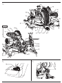 3
3
-
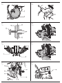 4
4
-
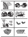 5
5
-
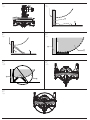 6
6
-
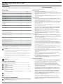 7
7
-
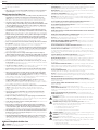 8
8
-
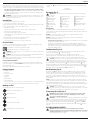 9
9
-
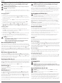 10
10
-
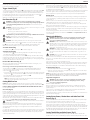 11
11
-
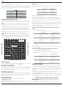 12
12
-
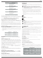 13
13
-
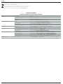 14
14
-
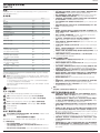 15
15
-
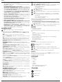 16
16
-
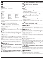 17
17
-
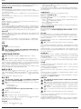 18
18
-
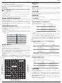 19
19
-
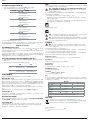 20
20
-
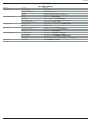 21
21
-
 22
22
-
 23
23
-
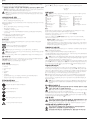 24
24
-
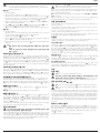 25
25
-
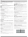 26
26
-
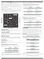 27
27
-
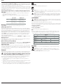 28
28
-
 29
29
-
 30
30
-
 31
31
-
 32
32


他の言語で
- English: DeWalt DWS713 User manual
関連論文
その他のドキュメント
-
Hilti SC 70W-A22 Cordless Circular Saw ユーザーマニュアル
-
Stanley SST1800 ユーザーマニュアル
-
-
-
Hikoki C3607DRA ユーザーマニュアル
-
Bosch GCM 216 Professional Mitre Saw ユーザーマニュアル
-
Bosch GCM 18V-305 ユーザーマニュアル
-
-
-
BLACK+DECKER KS701E ユーザーマニュアル