
SST1800
English Page 03
简体中文 页码 14

ENGLISH (Original instructions)/英语(原始说明书)
2
3
6
1
7
8
9
17
19
10
11
18
12
13
14
15
5
2
16
4
20
21b
21a
A
22

(Original instructions) ENGLISH
3
Intended use
Your STANLEY SST1800 Table Saw is designed for the slitting
and cross-cutting of all types of timber commensurate with the
machine’s size. This tool is intended for professional use.
SAFETY INSTRUCTIONS
WARNING! When using electric tools basic safety precautions
should be followed to reduce the risk of fire, electric shock and
personal including the following:
Read all these instructions before attempting to operate this
product and save these instructions
General Power Tool Safety Warnings
WARNING! Read all safety warnings and all
instructions. Failure to follow the warnings and
instructions may result in electric shock, fire and/or
serious injury.
Save all warnings and instructions for future reference.
The term “power tool” in the warnings refers to your
mains-operated (corded) power tool or battery-operated
(cordless) power tool.
1. Work area safety
a. Keep work area clean and well lit. Cluttered and dark
areas invite accidents.
b. Do not operate power tools in explosive atmospheres,
such as in the presence of flammable liquids, gases or
dust. Power tools create sparks which may ignite the dust
or fumes.
c. Keep children and bystanders away while operating a
power tool. Distractions can cause you to lose control.
2. Electrical safety
a. Power tool plugs must match the outlet. Never modify
the plug in any way. Do not use any adapter plugs with
earthed (grounded) power tools. Unmodified plugs and
matching outlets will reduce risk of electric shock.
b. Avoid body contact with earthed or grounded
surfaces such as pipes, radiators, ranges and
refrigerators. There is an increased risk of electric shock
if your body is earthed or grounded.
c. Do not expose power tools to rain or wet conditions.
Water entering a power tool will increase the risk of electric
shock.
d. Do not abuse the cord. Never use the cord for
carrying, pulling or unplugging the power tool. Keep
cord away from heat, oil, sharp edges or moving parts.
Damaged or entangled cords increase the risk of electric
shock.
e. When operating a power tool outdoors, use an
extension cord suitable for outdoor use. Use of a cord
suitable for outdoor use reduces the risk of electric shock.
f. If operating a power tool in a damp location is
unavoidable, use a residual current device (RCD)
protected supply. Use of an RCD reduces the risk of
electric shock. Note: The term “residual current device
(RCD)” may be replaced by the term “ground fault circuit
interrupter (GFCI)” or “earth leakage circuit breaker
(ELCB)”.
3. Personal safety
a. Stay alert, watch what you are doing and use common
sense when operating a power tool. Do not use a
power tool while you are tired or under the influence
of drugs, alcohol or medication. A moment of inattention
while operating power tools may result in serious personal
injury.
b. Use personal protective equipment. Always wear eye
protection. Protective equipment such as dust mask,
non-skid safety shoes, hard hat, or hearing protection
used for appropriate conditions will reduce personal
injuries.
c. Prevent unintentional starting. Ensure the switch is in
the off-position before connecting to power source
and/or battery pack, picking up or carrying the tool.
Carrying power tools with your finger on the switch or
energising power tools that have the switch on invites
accidents.
d. Remove any adjusting key or wrench before turning
the power tool on. A wrench or a key left attached to a
rotating part of the power tool may result in personal injury.
e. Do not overreach. Keep proper footing and balance at
at all times. This enables better control of the power tool
in unexpected situations.
f. Dress properly. Do not wear loose clothing or
jewellery. Keep your hair, clothing and gloves away
from moving parts. Loose clothes, jewellery or long hair
can be caught in moving parts.
g. If devices are provided for the connection of dust
extraction and collection facilities, ensure these are
connected and properly used. Use of these devices can
can reduce dust related hazards.
4. Power tool use and care
a. Do not force the power tool. Use the correct power
tool for your application. The correct power tool will do
the job better and safer at the rate for which it was
designed.
b. Do not use the power tool if the switch does not turn it
on and off. Any power tool that cannot be controlled with
the switch is dangerous and must be repaired.
c. Disconnect the plug from the power source and/or the
battery pack from the power tool before making any
adjustments, changing accessories, or storing power
tools. Such preventive safety measures reduce the risk of
starting the power tool accidentally.
d. Store idle power tools out of the reach of children and
do not allow persons unfamiliar with the power tool or
these instructions to operate the power tool. Power
tools are dangerous in the hands of untrained users.

NOT use a fence or fence system for cross-cutting.
Instead, use a miter gauge. USE PUSH STICK(S) for
ripping a narrow workpiece.
• AVOID AWKWARD OPERATIONS AND HAND
POSITIONS where a sudden slip could cause a hand to
move into the blade
• KEEP ARMS, HANDS, AND FINGERS away from the
blade
• NEVER have any part of your body in line with the path of
the saw blade.
• NEVER REACH AROUND or over the saw blade.
• NEVER attempt to free a stalled saw blade without first
turning the machine “OFF”.
• PROPERLY SUPPORT LONG OR WIDE workpieces.
• NEVER PERFORM LAYOUT, assembly or set-up work on
the table/work area when the machine is running.
• TURN THE MACHINE “OFF” AND DISCONNECT THE
MACHINE from the power source before installing or
removing accessories, before adjusting or changing
set-ups, or when making repairs.
• TURN THE MACHINE “OFF”, disconnect the machine
from the power source, and clean the table/work area
before leaving the machine. TURN THE SWITCH IN THE
“OFF” POSITION.
• Use push-sticks or push blocks to feed the workpice past
the saw blade
• Use and correct adjustment of the upper saw blade guard
• Do not use the saw blade if damaged or deformed.
• Use only the recommended saw blade, which conform to
EN847-1.
• When change saw blade, make sure the width of the
groove cut of the saw blade shall not be less than and the
thickness of the body of the saw blade shall not be more
than the thickness of the riving knife.
• Select the saw blade suitable for the material to be cut
• Wear suitable personal protective equipment include:
- hearing protection to reduce the risk of induced hearing
loss;
- eye protection
- respiratory protection to reduce the risk of inhalation of
harmful duct;
- gloves for handling saw blades and rough material (saw
blade should be carried in a holder wherever practicable)
• Connect to a dust-collecting device when sawing wood
• Do not use high speed steel (HS) saw blades
• Do not rebate or groove unless suitable guarding, such as
a tunnel guard, is fitted above the saw table;
• Do not use saws for slotting (stopped groove)
• Use only saw blades for which the maximum possible
speed is not less than the maximum spindle speed of the
tool and the material to be cut.
ENGLISH (Original instructions)
4
e. Maintain power tools. Check for misalignment or
binding of moving parts, breakage of parts and any
other condition that may affect the power tools
operation. If damaged, have the power tool repaired
before use. Many accidents are caused by poorly
maintained power tools.
f. Keep cutting tools sharp and clean. Properly
maintained cutting tools with sharp cutting edges are less
likely to bind and are easier to control.
g. Use the power tool, accessories and tool bits etc. in
accordance with these instructions, taking into
account the working conditions and the work to be
performed. Use of the power tool for operations different
from those intended could result in a hazardous situation.
5. Service
a. Have your power tool serviced by a qualified repair
person using only identical replacement parts. This will
ensure that the safety of the power tool is maintained.
TABLE SAWS SAFETY WARNINGS
Warning! Failure to follow these rules may result in
serious injury.
• DO NOT OPERATE THIS MACHINE until it is assembled
and installed according to the instructions.
• OBTAIN ADVICE FROM another qualified person if you
are not familiar with the operation of this machine.
• FOLLOW ALL WIRING CODES and recommended
electrical connections.
• ALWAYS USE THE GUARDS Check to see that they are
in place, secured, and working correctly.
• ALWAYS USE GUARDS, SPLITTER.
• REMOVE CUT-OFF PIECES AND SCRAPS from the
table before starting the saw. The vibration of the machine
may cause them to move into the saw lade and be thrown
out. After cutting, turn the machine off. After the blade has
come to a complete stop, remove all debris.
• NEVER START THE MACHINE with the workpiece
against the blade.
• NEVER run the workpiece between the fence and a
moulding cutterhead.
• CUTTING THE WORKPIECE WITHOUT THE USE OF A
FENCE OR MITER GAUGE IS KNOWN AS
“FREEHAND” CUTTING. NEVER perform “freehand”
operations. Use either the fence or miter gauge to position
and guide the workpiece.
• HOLD THE WORKPIECE FIRMLY against the miter
gauge or fence.
• CUTTING COMPLETELY THROUGH THE WORKPIECE
IS KNOWN AS “THROUGH-SAWING”. Ripping and
cross-cutting are through-sawing operations. Cutting with
the grain (or down the length of the workpiece) is ripping.
Cutting across the grain (or across the workpiece) is
cross-cutting. Use a fence or fence system for ripping. DO

(Original instructions) ENGLISH
5
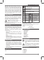
WARNING! TO REDUCE THE RISK OF INJURY,
THE USER MUST READ THE INSTRUCTION
MANUAL BEFORE USE.
Wear ear protection.
Wear safety glasses or goggles.
V Volts
Direct Current
A Amperes n
0
No-Load Speed
Hz Hertz
Class II Construction
W Watts
Earthing Terminal
min minutes
Safety Alert Symbol
Alternating
Current
/min.
Revolutions or
Reciprocation per
minute
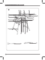
Position of Date Code (FIG. A)
The Date Code (10), which also includes the year of
manufacture, is printed into the housing.
Example:
2017 XX JN
Year of manufacturing
PACKAGE CONTENTS
• 1 SST1800 table saw
• 1 60T saw blade
• 1 Blade guard
• 1 Miter gauge
• 1 Rip fence
• 1 Extraction hose
• 1 Hose adapter
• 2 Spanner wrench
• 1 Push stick
ELECTRICAL SAFETY
Your tool is double insulated; therefore no earth
wire is required. Be sure to check that the power
supply corresponds to the voltage on the rating
plate.
If the supply cord is damaged, it must be replaced
by the manufacturer or an authorised STANLEY
Service Centre in order to avoid a hazard.
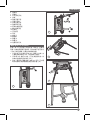
FEATURES (FIG. A)
This tool includes some or all of the following features.
1. Saw table
2. Blade guard
3. Riving knife
4. Saw blade
5. Rip fence
Note: Mains voltage: When connecting to the mains, it is
imperative to verify if the voltage of the mains matches that of
the power tool. If the mains voltage exceeds the voltage
indicated on the power tool, the user may become severely
injured in an accident, and the tool may be damaged. On the
contrary, if the mains voltage is lower than the voltage
required by the tool, the motor may be damaged as a result.
Thus, if it is not possible to verify the voltage, it is imperative
not to plug in to the power source.
POWER CONNECTIONS
Before connecting the machine to the power line, make sure
the switch (s) is in the “OFF” position and be sure that the
electric current is of the same characteristics as indicated on
the machine. All line connections should make good contact.
Running on low voltage will damage the machine.
Danger! Do not expose the machine to rain or
operate the machine in damp locations.
Before connecting the machine to the power source, make
sure the switch is in the “OFF” position.
RESIDUAL RISKS
Additional residual risks may arise when using the tool which
may not be included in the enclosed safety warnings. These
risks can arise from misuse, prolonged use etc. In spite of the
application of the relevant safety regulations and the
implementation of safety devices, certain risks cannot be
avoided. These are:
• Injuries caused when changing any parts, blades or
accessories.
• Injuries caused by prolonged use of a tool. When using
any tool for prolonged periods ensure you take regular
breaks.
• Impairment of hearing.
• Health hazards caused by breathing dust developed when
using your tool (example: working with wood, especially
oak, beech and MDF.)
SAFETY OF OTHERS
• This appliance is not intended for use by persons
(including children) with reduced physical, sensory or
mental capabilities, or lack of experience and knowledge,
unless they have been given supervision or instruction
concerning use of the appliance by a person responsible
for their safety.
• Children should be supervised to ensure that they do not
play with the appliance.
LABELS ON TOOL
The following symbols are shown on the tool along with date
code:

ENGLISH (Original instructions)
6
6. Mitre guage
7. Transportation wheels
8. On/Off switch
9. Leg stand
10. Bevel adjustment locking knob
11. Blade elevation handle
12. Leg stand locking knob
13. Blade tilting wheel
14. Locking handle for extension table
15. Locking handle for rip fence
16. Extension table
17. Spanner wrench
18. Guide rail
19. Push stick
20. Table insert
21. Groove (a)
21. Groove (b)
22. Overloaded protector
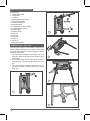
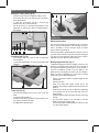
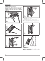
ASSEMBLY (Fig. A1, A2, A3, A4)
There are three positions on the machine for different use,
standing, folding and transporting. The legs are locked using
twist knobs which lock/unlock in either direction and have a
central unlocked position.
1. Start with the saw standing on its wheels (A1), unlock the
upper legs. Swing up the legs and lock (A2) then unlock
the lower legs.
2. Lift the table from the end (A3), allowing the lower leg to
swing into place. Swing the leg fully into place and lock
(A4).
3. There is a adjustable spring leg as shown in Fig.A5. You
can rotate it clockwise or anti-clockwise for your desired
length. (A5)
A1
1
3
2
A2
1
2
A3
A4
A5

(Original instructions) ENGLISH
7
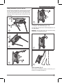
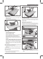
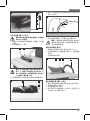
To Transport The Table Saw (Fig C1, C2)
The upper legs could be locked in the vertical position for use
as a trolley handle.
WARNING! Cover the upper part of the saw blade during
transportation, for example by the guard
Handle assembly (Fig. D)
Place washer (e), housing (b), washer (c) and hex nut (d) on
the bolt (a) to assemble the handle (11)
Folding instructions (Fig. B1, B2, B3, B4)
Hold and support the table edge, unlock the legs at the wheel
end (B1).Lower the wheels to the ground, allowing the legs to
swing under (B2).Stand the table on end, fold up and lock the
lower legs, unlock the upper legs (B3). Swing down the legs
and lock (B4).
1
3
2
B3
1
3
2
B1
1
B2
1
2
B4
C2
C1

ENGLISH (Original instructions)
8
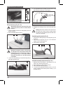
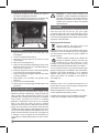
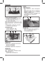
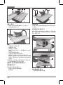
4. The gap between the saw blade (4) teeth and the riving
knife should be around 3mm to 5mm (Fig.G)
5. R-tighten the mounting screw (f) and fix the table insert
(20)
Warning! Ensure the machine is disconnected from
the power source. Never user the machine without
the table insert; Immediately replace the table insert
when worn or damaged
Saw blade guard assembly (Fig. H)
1. Fasten the saw blade guard (2) to the riving knife (5) with
the bolt (g).
2. Place the rear extraction hose (h) on the extraction
adapter on the saw blade guard (2).
3. Disassembly in reverse order.
Saw blade assembly/replacement (Fig. E, H, I)
1. Warning: Ensure the machine is disconnected from the
power source. Wear the safety gloves.
2. Disassemble the saw blade guard (2) (Fig. H.)
3. Remove the table insert (20) (Fig. E).
4. Loosen the nut by placing the spanner wrench (17) on the
nut and countering with another spanner wrench (17) on
the flange (Fing. I).
Riving knife set-up (Fig. E, F, G)
Warning! Disconnect the mains cable! The setup
of the riving knife (3) must be checked before
each use.
1. Set the saw blade (4) to the max. cutting depth, put it at 00
position and lock it
2. Remove the table insert (20) (Fig. E)
Warning! For transport reasons, the riving knife
(3) was fixed in the lower position before initial
commissioning. Only work with the machine if
the riving knife (3) is in the upper position.
Fitting the riving knife (3) in the upper position
is as follows:
3. Loosen the locking handle (f) and push the riving knife (3)
in the upper position (Fig.F)
D
d
c
b
e
a
11
E
204
F
f
34
G
max. 3-5 mm
2 3
g
h
H

(Original instructions) ENGLISH
9
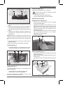
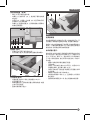
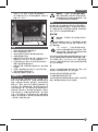
Setting the angle (Fig. J)
Set the required bevel angle from 0 to 45 degree
Before cutting, ensure the saw blade (4) and mitre
gauge (6) no collision
- Loose the Bevel adjustment locking knob (10).
- Set up the desired angle then lock the knob again
Working with the rip fence
Setting the fence height (Fig. K)
- The fence rail (i) of the rip fence (5) has two guiding
surface with different heights.
- Depending on the thickness of the material to be cut, the
higher side of the fence rail (i) has to be used for thick
material (work piece thickness above 25mm) and the
lower side of the fence rail for thin material (work piece
thickness below 25mm).
- For the adjustment, loosen the bolts on the side of the rip
fence (5) and push the fence rail (i) on he guide,
depending on the required position.
- Tighten the bolts again.
Rip fence assembly (Fig. L)
- Fix the rip fence (5) at the back side and press the locking
handle (15) downwards.
- When disassembly, pull the locking handle up and remove
the rip fence (5).
- The rip fence could be locked setting with the rear knurled
nut.
5. Warning! Turn the nut in the rotational direction of the saw
blade.
6. Remove the outer flange and take out the saw blade from
the inner flange, with diagonally downwards movement.
7. Carefully clean the flange with a before fixing the new saw
blade.
8. Insert the new saw blade and fasten the outer flange. The
outer flange has a �30mm raised boss which fits in side
the blade bore.
Warning! The teeth of a new blade are very sharp and can be
dangerous. Make sure the teeth point down at the front of the
table, aligned with the arrow marked on the saw blade guard
(2).
9. Attach the table insert (20) and the saw blade guard (2)
again and set them.
10. Before working, check the functionality of the guards.
On/Off switch (Fig. J)
- To switch the machine on, press the green start “I” button.
- To switch the machine off, press the red stop “O” button.
Cutting depth (Fig. J)
Turn the blade elevation handle (11) to set the blade to the
required cutting depth.
- Turn anti-clockwise; to increase the cutting depth
- Turn Clockwise; to reduce the cutting depth
After each new adjustment it is advisable to carry out a trial
cut in order to check the set dimensions.
I
17 17
J
8
11
10
K
i5
L
515

ENGLISH (Original instructions)
10
M
5
18 k l m
N
14 16
O
6 21an
p
OPERATION
Working instructions
After each new adjustment it is advisable to carry out a trial in
order to check the set dimensions. After switching on the saw,
wait for the blade to reach its maximum speed of rotation
before commencing with the cut.
Secure long workpiece against falling off at the end of the cut
(e.g. with a roller stand etc.) Take extra care when starting the
cut! Never use the equipment without the suction function.
Regularly check and clean the suction channels.
Making longitudinal cuts (Fig. P)
Longitudinal cutting (also known as slitting) is when you use
the saw to cut along the grain of the wood. Press one edge of
the workpiece against the parallel stop (5)” to be replaced to
“rip fence (5) while the flat side on the saw table (1). The
blade guard (2) must always be lowered over the workpiece.
When you make a longitudinal cut, never adopt a working
position that is in line with cutting direction.
- Set the in accordance with the workpiece height and the
desired width.
- Switch on the saw.
- Place your hands (with fingers closed) flat on the
workpiece and push the workpiece along the and into the
blade (4).
- Guide at the side with your left or right hand (depending
on the position) only as far as the front edge of the saw
blade guard (2).
- Always push the workpiece through to the end of the riving
knife (3)
- The offcut piece remains on the saw table (1) until the
blade (4) is back in its position of rest.
- Secure long workpiece against falling off at the end of the
cut ) with a roller stand etc.
Setting the cutting width (Fig. M)
- The rip fence (5) is used for lengthwise cutting of wood.
- Place the rip fence (5) on the guide rail (18) to the right or
left of the saw blade.
- 2 scales (k/l) on the guide rail (18) to show the gap
between fence rail (i) and saw blade (4)
- Set the rip fence (5) to the required specification on the
sight-glass (m) and secure it with the locking handle for
the rip fence.
Extension table (Fig. N)
- The extension table (16) could be used for particularly
wide workpieces
- Loosen the locking handle (14) and pull out the table width
extension.
Cross stop (Fig. O)
- Push the miter gauge (6) into a slot (21 a/b) on the saw
table.
- Loosen the locking handle (n).
- Rotate the miter gauge (6) until the required angle is set.
The scale (p) shows the set angle.
- Re-tighten the locking handle (p).

(Original instructions) ENGLISH
11
- Proceed as for cross cutting
Cutting particle boards
To prevent the cutting edges from cracking when working with
particle boards, the saw blade must be higher than the
workpiece height.
Auxiliary tools stored (Fig. S, T)
Auxiliary tools can be stored on the machine Miter gauge (6)
could be put on hook as Fig S showed. Blade guard (2) and
push stick (19) could be put on hook as Fig T showed.
Blade jamming handling (Fig. U)
- Ensure the machine is disconnected from the power
source.
Caution: (Fig. Q)
- Always use the push stick (19) when ripping small
workpieces (fig. Q)
- Do not cut excessively small workpieces.
Cross Cutting
- Lock the miter gauge (6) at 0 degree
- Set the bevel angle to 0 degree
- Adjust the saw blade (4) height
- Hold the workpiece flat on the table (1) and against the
fence. Keep the workpiece away from the blade.
- Keep both hands away from the path of the saw blade.
- Switch the machine on and allow the saw blade to reach
full speed.
- Hold the workpiece tightly again the fence and slowly
move the workpiece together with the fence assembly until
the workpiece comes underneath the upper blade guard.
Allow the teeth to cut, and do not force the workpiece
through the saw blade. The saw blade speed should be
kept constant.
After completing the cut, switch the machine off, allow the saw
blade to stop and remove the workpiece
- Push the and the workpiece toward the blade in order to
make the cut.
Important: Never push or hold the cut-off-side workpiece.
Bevel cuts (Fig. R)
Bevel cuts must always be made using the rip fence (5).
- Set the blade (4) to the desired angle.
P
5
3
2
4 1
Q
19
R
621a 21b4
S
6
T
2
19

ENGLISH (Original instructions)
12
Important! To assure product SAFETY and
RELIABILITY, repairs, maintenance and adjustment
(other than those listed in this manual) should be
performed by authorized service centers or other
qualified service personnel, always using identical
replacement parts.
ACCESSORIES
We recommend that you purchase your accessories from the
same store that sold you the tool. Use good quality
accessories marked with a well- known brand name. Choose
the type according to the work you intend to undertake. Refer
to the accessory packaging for further details. Store personnel
can assist you and offer advice.
Protecting the Environment
Separate collection. This product must not be
disposed of with normal household waste.
Should you find one day that your STANLEY product needs
replacement, or if it is of no further use to you, do not dispose
of it with household waste. Make this product available for
separate collection.
STANLEY provides a facility for the collection and
recycling of STANLEY products once they have
reached the end of their working life. To take
advantage of this service please return your product to any
authorised repair agent who will collect them on our behalf.
You can check the location of your nearest authorised repair
agent by contacting your local STANLEY office at the address
indicated in this manual. Alternatively, a list of authorised
STANLEY repair agents and full details of our after-sales
service and contacts are available on the Internet at:
www.2helpU.com.
Notes
STANLEY’s policy is one of continuous improvement to our
products and as such, we reserve the right to change product
specifications without prior notice.
Standard equipment and accessories may vary by country.
Product specifications may differ by country.
Complete product range may not be available in all countries.
Contact your local STANLEY dealers for range availability.
- Remove the wookpiece at first. Warning: Be careful of
your hands not toughing the saw blade.
- Press the overloaded protector(22) and connect the plug
again, the machine can be resumed to work. (Fig U)
APPLICATIONS
1. Make sure the kerf is made on the scrap side of the
measuring line.
2. Cut the wood with the finished side up.
3. Always have a proper support for the wood as it comes
out of the blade.
4. Make a test cut for important cuts.
5. Always use the correct blade depth setting. The top of the
blade teeth should clear the top of the material being cut
by 1⁄8” (3 mm) to 1⁄4” (6 mm).
6. Inspect the work-piece for knots or nails before beginning
a cut. Remove any loose knots with a hammer.
7. Always use clean, sharp, properly-set blades. Never make
a cut with a dull blade.
8. When making a cut, use steady, even pressure. Never
force a cut.
9. DO NOT cut wet or warped lumber.
10. Always hold your work-piece firmly with both hands or use
a push stick.
MAINTAIN TOOLS WITH CARE
Remove the plug from the socket before carrying out any
adjustment, servicing or maintenance. Keep tools sharp and
clean for better and safer performane. Inspect tool cords
periodically and if damaged, have repaired by an authorized
service facility. Your power tool requires no additional
lubrication or maintenance. There are no user serviceable
parts in your power tool. Never use water or chemical
cleaners to clean your power tool. Wipe clean with a dry cloth.
Always store your power tool in a dry place. Keep the motor
ventilation slots clean. Keep all working controls free of dust. If
you see some sparks flashing in the ventilation slots, this is
normal and will not damage your power tool. If the supply cord
is damaged, it must be replaced by the manufacturer, its
service agent or similarly qualified persons in order to avoid a
hazard.
U
22

(Original instructions) ENGLISH
13
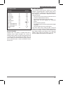
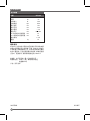
TECHNICAL DATA
Service Information
STANLEY offers a full network of company-owned and/ or
authorized service agents throughout your country. All
STANLEY Service Centers are staffed with trained personnel
to provide customers with efficient and reliable power tool
service. Whether you need technical advice, repair, or genuine
factory replacement parts, contact the STANLEY location
nearest to you.
ONE YEAR WARRANTY
If your STANLEY product becomes defective due to faulty
materials or workmanship within 12 months from the date of
purchase, STANLEY guarantees to replace all defective parts
free of charge or – at our discretion – replace the unit free of
charge provided that:
• The product has not been misused and has been used in
accordance with the instruction manual;
• The product has been subject to fair wear and tear;
• Repairs have not been attempted by unauthorized
persons;
• Proof of purchase is produced.
• The STANLEY product is returned complete with all original
components
• The product hasn’t been used for hire purposes
If you wish to make a claim, contact your seller or check the
location of your nearest authorised STANLEY repair agent in
the STANLEY catalogue or contact your local STANLEY office
at the address indicated in this manual. A list of authorised
STANLEY repair agents and full details of our after sales
service is available on the internet at: www.2helpU.com
Voltage V
Frequency Hz
Power input W
No-load speed rpm
Blade diameter mm
Bore Size mm
220-240
50/60
1800
4800
254
25.4
Blade thickness mm > 2.8
Table size mm 640x 640
Max. cutting depth at 45º mm 50
Max. cutting depth at 90º mm 80
Blade bevel range 0 - 45º
Weight kg 35
Table Saw SST1800

中文说明书
14
预期用途
STANLEY SST1800 台锯设计用于切割和横切所有类型
的木材,其尺寸与机器尺寸相称。该工具计划用于专
业用途。
安全说明书
警告!使用电动工具时,应遵循基本的安全预防措施,
以降低着火、电击和人身伤害的风险,包括:
在尝试操作本产品之前,请阅读并保存所有这些说
明书。
电动工具通用安全警告
警告!阅读所有安全警告和说明书。未遵照
下列警告和说明书可能会导致电机、着火和/
或严重伤害。
保存所有警告和说明书以备将来参考。警告中的术语
“电动工具”指的是电源操作(有线)电动工具或电池
供电(无线)电动工具。
1.
工作场地安全
a. 保持工作场地清洁和明亮。杂乱和黑暗的场地会
引发事故。
b. 请勿在易爆环境,如有易燃液体、气体或粉尘的环
境下操作电动工具。电动工具产生的火花会点燃
粉尘或气体。
c. 操作电动工具时,远离儿童和旁观者。 集
中会使你失去对工具的控制。
2.
电气安全
a. 电动工具插头必须与插座相匹配。禁止以任何方
式改装插头。对于需接地的电动工具,请勿使用任
何配接器插头。未经改装的插头和相匹配的插座
将降低电击风险。
b. 避免人体接触接地表面,如管道、散热片、炉灶和
冰箱。如果身体接触接地表面,则会增加电击风险。
c. 请勿将电动工具暴露在雨中或潮湿环境中。一旦
水流经电动工具,会增加电击风险。
d. 请勿滥用软线。禁止用软线搬运、拉动电动工具
或拔掉其插头。使软线远离热源、油、锐边或运动
零件。受损或缠绕的软线会增加电击风险。
e. 在户外操作电动工具时,使用适合户外使用的延
长软线。适合户外使用的软线会降低电击风险。
f. 如果无法避免在潮湿环境下操作电动工具,则使用
带有剩余电流装置 (RCD) 保护的电源。使用 RCD
会降低电击风险。注:术语“剩余电流装置 (RCD)”
可更换为术语“接地故障断路器 (GFCI)”或“接地漏
电断路器 (ELCB)”。
3.
人身安全
a. 操作电动工具时,保持警惕,观察正在做什么,并运
用常识。感到疲倦或受毒品、
酒精或药物影响时,
请勿操作电动工具。在操作电动工具时瞬间的疏
忽可能会导致严重的人身伤害。
b. 使用个人防护用品。始终佩戴护目镜。防护用品,
如在适当条件下使用的防尘面具、防滑安全鞋、
安全帽、听力保护装置等,会减少人身伤害。
c. 防止意外启动。连接电源和/或电池组、拿起或搬
运电动工具之前,确保开关处于断开位置。将手指
放在开关上搬运电动工具或给打开开关的电动工
具通电会引发事故。
d. 打开电动工具之前,拆下所有调节钥匙或扳手。
遗留在电动工具旋转零件上的扳手或钥匙可能会
导致人身伤害。
e. 请勿过度伸展。始终保持适当站稳和平衡。这样可
在意外情况下更好地控制电动工具。
f. 着装恰当。请勿穿宽松衣服或佩戴饰品。使头发、
衣服和手套远离运动零件。宽松衣服、佩饰或长发
可能会卷入运动零件中。
h. 如果配备了连接除尘和集尘设施的装置,确保这
g. 保持手干燥、清洁且没有油脂。油腻的手柄对
于意外情况下的工具安全握持和控制是不允许的。
些装置连接完好且使用得当。使用这些装置可降
低粉尘引起的相关危险。
4.
电动工具使用和注意事项
a. 请勿强行使用电动工具根据应用需求,使用合适
的电动工具。使用合适的按照额定值设计的电动
工具会使您工作更有效、更安全。
b. 如果无法打开或关闭开关,请勿使用电动工具。
无法使用开关来控制的电动工具,具有危险性且
必须进行修理。
c. 在进行任何调节、更换配件或贮存电动工具之前,
断开电源插头和/或电池组。这种预防性的安全措
施降低了意外启动电动工具的风险。
d. 将闲置不用的电动工具贮存在儿童所及范围之外,
并且不熟悉电动工具或不了解这些说明的人员不
允许操作电动工具。若未经培训的使用者操作电
动工具,则具有危险性。

• “关闭”机器,断开机器与电源的连接,并在离
开机器前清洁工作台/工作区域。将开关置于“关闭”
位置。
• 使用推杆或推块将工件进料至锯片上。
• 使用并正确调整上锯片护罩。
• 如果锯片损坏或变形,请勿使用。
• 仅使用符合 EN847-1 的推荐锯片
• 更换锯片时,确保锯片的槽切宽度不小于分料刀的
厚度,锯片的主体厚度不大于分料刀的厚度。
• 选择适合切割材料的锯片。
• 穿戴合适的个人防护用品包括:
- 听力保护装置,以降低诱发听觉损失的风险;
- 眼睛保护装置;
- 呼吸保护装置,以降低吸入有害管道的风险;
- 处理锯片和粗糙材料的手套(如可行,锯片应装在
手柄中);
• 锯木时,将锯片连接至集尘装置上;
• 请勿使用高速钢 (HS) 锯片;
• 除非在工作台上方安装通道护罩等适当的防护装
置,否则请勿回扣或开槽;
• 请勿使用台锯开槽(停止开槽);
• 仅使用最大可能速度不小于工具和要切割材料的
• 不要使用损坏或变形的锯片;
• 如果护罩不在其应有位置上,不得使用工具;
• 更换磨损了的工作台嵌衬;
• 能够锯割的材料规格;
• 不得锯割未推荐的材料;
• 锯割时要装上集尘装置;
• 只允许使用制造厂推荐的锯片;
• 根据被锯割的材料选择锯片;
• 要选择推棒把工件推过锯片;
• 使用并正确调整分料刀;
• 使用和正确调整锯片上的护罩。
最大转速的锯片。
e. 维护电动工具。检查运动零件是否移位或绑住,
检查零件的破损状况和可能影响电动工具操作的
其它状况。如有损坏,在使用前应修理好电动工具。
许多事故是由电动工具维护不良造成的。
f. 保持刃具锋利和清洁。具有锋利切削刃的维护不
良的刃具不易卡住且更容易控制。
g. 根据这些说明书,并考虑作业条件和要进行的作业,
使用电动工具、配件和刃头等。使用电动工具进行
与预期不同的操作可能会导致危险的情况。
5.
维修
a. 由合格维修人员使用完全相同的替换件维修电动
工具。这将保证所维修的电动工具的安全。
台锯安全警告
警告!未遵守这些规则可能会导致严重的伤害。
• 在根据说明书组装和安装机器之前,请勿操作该机器。
• 从其他合格人员处
获取建议。
• 遵守所有接线规范和推荐的电气连接
• 始终使用护罩检查它们是否安装到位、安全并正
常工作。
• 始终使用护罩和分离机。
• 启动台锯之前,从工作台上拆下切块和残片。机器
的振动可能使它们移入锯片并被抛出。切割后,
关
掉机器。待锯片完全停止转动后,清除所有碎片。
• 禁止将工件靠在锯片上启动机器
• 禁止将工件夹在靠山与模压刀盘之间运行。
• 不使用靠山或角度器切割工件被称为“徒手”切割
。禁止进行“徒手”操作。使用靠山或角度器来定
位和牵引工件。
• 将工件牢固地固定在角度器或靠山上。
• 完全通过工件切割被称为“贯通锯切”劈裂和横切
是贯通锯切操作。使用颗粒物(或沿工件的长度)
切割是劈裂。横切颗粒物(或工件)是横切。使用
靠山或靠山系统劈裂。请勿使用靠山或靠山系统
横切。相反,可使用斜接规。使用推料刀劈裂狭小
工件。
• 避免笨拙的操作和手部姿势,其中身体突然滑倒
可能导致手卡入锯片中。
• 使手臂、手和手指远离锯片。
• 禁止让身体的任何部位与锯片的运动路径一致。
• 禁止靠近或越过锯片。
• 禁止在未首先“关闭”机器的情况下尝试释放失速
的锯片。
• 适当支撑长的或宽的工件。
• 运行机器时,禁止在工作台/工作区域进行布置、装
配或设置工作。
• 安装或拆卸配件、调整或更换
设置之前,或维修时,
“关闭”机器并断开机器与电源的连接。
15
中文说明书

注:电源电压:连接电源时,务必验证电源电压是否与
电动工具的电压相匹配。如果电源电压超过电动工具
上所显示的电压,则用户可能会在事故中严重受伤,
并且可能损坏工具。相反,如果电源电压低于电动工
具所需的电压,则电机可能会因此而损坏。因此,如果
无法验证电压的匹配程度,则务必不插入电源。
电源连接
在将机器连接到电源线之前,确保开关处于“关闭”
位置,并确保电流与机器上所显示的电流相同。所有
线路连接均应接触良好。低压运行会损坏机器。
危 险!请勿将机器暴露在雨中或在潮湿的地
方操作机器。
在将机器连接到电源之前,确保开关处于“关闭”位置。
剩余风险
使用该工具时可能会产生额外的残余风险,这些风险
可能未包含在随附的安全警告中。这些风险可能是由
于误用、长时间使用等造成的。尽管采用了相关的安全
法规和实施了安全装置,但仍然存在某些风险。包括:
• 更换任何零件、刀片或附件时造成的伤害。
• 长时间使用工具造成的伤害。长时间使用任何工
具 时 ,确 保 定 期 休 息 。
• 听力受损。
• 使用工具时产生的呼吸性粉尘造成的健康危害(例如:
使 用 木 材 ,特 别 是 橡 木 、山 毛 榉 和 MDF 作 业 )。
他人的安全
• 本 装 置 不 适 合 身 体 、感 官 或 精 神 能 力 下 降 、缺 乏 经
验和知识的人员(包括儿童)使用,除非负责其安全
的人员为他们提供使用本装置方面的监督或指导。
• 应对儿童进行监督,以确保他们不会玩弄此装置。
工具上的标签
以下标志与日期代码一起显示在工具上:
警告!为了降低伤害风险,使用者在使
用前必须阅读说明书。
戴护耳用具。
戴安全眼镜或护目镜。
V 伏特
直流
A 安培 n
0
空载速度
Hz 赫兹
二级结构
W 瓦特
接地端子
min 分钟
安全警告标志
交流
/min.
每分钟的转数或往
复次数
日 期 代 码 位 置( 图 A )
日期代码 (10), 也包括制造年份,被印刷在外壳上。
示例:
2017 XX JN
制造年份
包装清单
• 1 SST1800 台锯
• 1 60T 锯片
• 1 个锯片护罩
• 1 台角度器
• 1 块靠山
• 1 根抽取软管
• 1 个软管配接器
• 2 把开口扳手
• 1 把推料刀
电气安全
工具需要接地。务必检查电源是否与标牌上的电压
相符。
如果电源软线损坏,必须由制造商或授权的
STANLEY 服务中心更换,以避免发生危险。
结 构( 图 A)
此工具包括以下部分或全部结构。
1. 工作台
2. 锯片护罩
3. 分料刀
4. 锯片
5. 靠山
16
中文说明书

6. 角度器
7. 运输轮
8. 打开/关闭开关
9. 支架
10. 角度压紧手把
11. 升降小手轮
12. 支架压紧手把
13. 角度调节手轮
14. 延伸台锁紧手把
15. 靠山锁紧手把
16. 延伸台
17. 开口扳手
18. 导杆
19. 推料刀
20. 辅助板
21. 滑槽 (a)
21. 滑槽 (b)
22. 过载保护开关
装 配( 图 A1, A2, A3 和 A4)
机器上有三个位置供不同的用途,即站立、折叠和
运输。支架使用扭转手把锁定,其中旋转手把可在任
一方向上锁定/解锁,并具有中央解锁位置。
1. 从立在轮子上的锯片开始(A1),解 锁 上 支 架 。向
上摆动支架并锁定(A2),然 后 解 锁 下 支 架 。
2. 从 末 端( A3)抬 起 工 作 台 ,让 下 支 架 摆 动 到 位 。将
支架完全摆动到位并锁定(A4)。
3. 存在一根调节式弹簧支架,如图 A5 所 示 。可 以 顺
时针或逆时针旋转弹簧支架至所需长度。(A5)
A1
1
3
2
A2
1
2
A3
A4
A5
17
中文说明书

为 运 输 台 锯( 图 C1 和 C2)
上支架可锁定在垂直位置,以用作台车手柄。
警 告! 在运输过程中,例如通过护罩,覆盖锯片的上部。
手 柄 装 配( 图
D)
将垫圈 (e), 外壳 (b), 垫圈 (c) 和六角螺母 (d) 放置在
螺栓 (a) 上 ,以 组 装 手 柄 (11)
折 叠 说 明( 图 B1, B2, B3 和 B4)
固定并支撑台边,解锁轮子末端的支架 (B1)。将 轮 子
降 到 地 面 ,让 支 架 在 (B2) 向 下 摆 动 。将 工 作 台 竖 着 放 ,
折叠并锁定下支架,解锁上支架 (B3)。向 下 摆 动 支 架
并锁定 (B4)。
1
3
2
B3
1
3
2
B1
1
B2
1
2
B4
C2
C1
18
中文说明书

4. 锯片 (4) 切齿与切刀之间的间隙分料刀应长约 3mm
至 5mm(图 G)
5. 再次拧紧安装螺钉 (f),并 固 定 工 作 台 插 件 (20)
警 告! 确 保 机 器 与 电 源 断 开 连 接 。禁 止 在 无
辅助板时使用机器;机器磨损或损坏时,
请立即更换辅助板
锯 片 防 护 装 配( 图 H)
1. 用螺栓 (g) 将锯片护罩 (2) 固定在分料刀 (5) 上。
2. 将后提取软管 (h) 放置在锯片护罩 (2) 上的提取配
接器上。
3. 以相反的顺序拆卸。
锯 片 装 配 / 更 换( 图 E, H 和 I)
1. 警告:确保机器与电源断开连接。戴上安全手套。
2. 拆卸锯片护罩 (2)(图 H.)。
3. 拆下辅助板 (20)(图 E)。
4. 把开口扳手 (17) 放在螺母上,并用另一开口扳手 (17)
反扣法兰,松开螺母(图 I)。
分 料 刀 设 置( 图 E, F 和 G)
警告!断开电源电缆!每次使用前,必须检查
分料刀 (3) 的设置。
1. 将锯片 (4) 设置为最大切割深度,将其置于 00 位置
并锁定
2. 拆下辅助板 (20)(图 E)
警告!为了实现运输,在初次调试之前,将分
料刀 (3) 固定在下部位置。仅当分料刀 (3)
处于上部位置时,才能使用机器。将分料刀
(3) 安装在上部位置,如下:
3. 松开锁紧手把 (f),并 将 分 料 刀 (3) 推 到 上 部 位 置( 图 F)
D
d
c
b
e
a
11
E
204
F
f
34
G
最大 3-5 m m
2 3
g
h
H
19
中文说明书

使用靠山
设 置 靠 山 高 度( 图 K)
- 靠山 (5) 的靠山导杆 (i) 具有两个不同高度的导 杆
表面。
- 根 据 待 切 割 材 料 的 厚 度 ,靠 山 导 杆 (i) 的较高侧必须
使 用 厚 材 料( 工 件 厚 度 大 于 25mm),其 下 侧 必 须 使
用 薄 材 料( 工 件 厚 度 低 于 25mm)。
- 为了调节靠山导杆,松开靠山 (5) 侧 面 的 螺 栓 ,并 根
据所需位置将靠山导杆 (i) 推到导向器上。
- 再次拧紧螺栓。
靠 山 装 配( 图 L)
- 将靠山 (5) 固定在后侧,然后向下按锁定手柄 (15)。
- 拆 卸 时 ,向 上 拉 锁 紧 手 把 并 拆 下 靠 山 (5)。
- 可以用后滚花螺母锁定靠山。
5. 警告!沿锯片的旋转方向转动螺母。
6. 拆下外法兰,从内法兰取出锯片,并斜向下移动。
7. 在固定新锯片之前,仔细清洁法兰。
8. 插入新锯片,并固定外锯片。外法兰配有 �30mm 的
凸台,其安装在锯片孔的侧面。
警 告!新锯片的切齿很锋利,可能具有危险性。确保切
齿尖朝下放置在据台前面,与锯片护罩上标记的箭头
对齐 (2)。
9. 再次安装辅助板 (20) 和锯片护罩 (2) 并进行固定。
10. 在使用机器之前,检查护罩的功能。
打开/关闭开关(图 J)
- 打 开 机 器 ,请 按 绿 色 开 始 “I” 按钮。
- 关 闭 机 器 ,请 按 红 色 停 止 “O” 按钮。
切 割 深 度( 图 J)
转动升降小手轮 (11) 将锯片设置为所需的切割深度。
- 逆时针转动;增加切割深度
- 顺时针转动;减少切割深度
每次重新调整后,建议进行试切,以检查设定尺寸。
设定角度(图 J)
将所需的斜角设置为 0 到 45 度
切 割 前 ,确 保 锯 片 (4) 和角度器 (6) 无碰撞
- 松开角度压紧手把 (10)。
- 设 置 所 需 的 角 度 ,然 后 再 次 锁 定 手 把
I
17 17
J
8
11
10
K
i5
L
515
20
中文说明书
ページが読み込まれています...
ページが読み込まれています...
ページが読み込まれています...
ページが読み込まれています...
-
 1
1
-
 2
2
-
 3
3
-
 4
4
-
 5
5
-
 6
6
-
 7
7
-
 8
8
-
 9
9
-
 10
10
-
 11
11
-
 12
12
-
 13
13
-
 14
14
-
 15
15
-
 16
16
-
 17
17
-
 18
18
-
 19
19
-
 20
20
-
 21
21
-
 22
22
-
 23
23
-
 24
24


