
STSC2135
4
9
English (Original Instruction)

DIAMETER OF WORK PIECE
WIDTH OF SPACE BLOCK
SPACE BLOCK
E
F
Z
.3"
(8mm)
FIG.1 FIG.2
FIG.5
FIG.9
FIG.4
E
H
I
F
FORWARD
FIG.7
L
FIG.8
R
J
U
T
S
Y
W
V
K
J
F
H
I
L
N
o
A
M
G
X
E
D
FIG.3
CUT-OFF END
BLOCK
C
B
F
P
Q
E
FIG.6
P
E
QD

3
ENGLISH
INTENDED USE
Your Stanley STSC2135 Chop Saw has been designed for
cutting of variously shaped steel materials.
GENERAL SAFETY RULES
Warning! Read all instructions. Failure to follow all
instructions listed below may result in electric shock, fire
and/or serious injury. The term “power tool” in all of the
warnings listed below refers to your mains operated
(corded) power tool or battery operated (cordless) power
tool. SAVE THESE INSTRUCTIONS.
1. Work area
a. Keep work area clean and well lit. Cluttered and
dark areas invite accidents.
b. Do not operate power tools in explosive
atmospheres, such as in the presence of
flammable liquids, gases or dust. Power tools
create sparks which may ignite the dust or fumes.
c. Keep children and bystanders away while
operating a power tool. Distractions can cause you
to lose control.
2. Electrical safety
a. Power tool plugs must match the outlet. Never
modify the plug in any way. Do not use any
adapter plugs with earthed (grounded) power
tools. Unmodified plugs and matching outlets will
reduce risk of electric shock.
b. Avoid body contact with earthed or grounded
surfaces such as pipes, radiators, ranges and
refrigerators. There is an increased risk of electric
shock if your body is earthed or grounded.
c. Do not expose power tools to rain or wet
conditions. Water entering a power tool will increase
the risk of electric shock.
d. Do not abuse the cord. Never use the cord for
carrying, pulling or unplugging the power tool.
Keep cord away from heat, oil, sharp edges or
moving parts. Damaged or entangled cords increase
the risk of electric shock.
e. When operating a power tool outdoors, use an
extension cord suitable for outdoor use.
Use of a
cord suitable for outdoor use reduces the risk of
electric shock.
f. If operating a power tool in a damp location is
unavoidable, use a residual current device
(RCD)protected supply.Use of an RCD reduces the
risk of electric shock.
NOTE: The term "Residual Curent Device (RCD)" can be
replaced by "Ground Fault Circuit Interrupter (GFCI)" or
by "Earth Leakage Circuit Breaker (ELCB)".
3. Personal safety
a. Stay alert, watch what you are doing and use
common sense when operating a power tool. Do
not use a power tool while you are tired or under
the influence of drugs, alcohol or medication. A
moment of inattention while operating power tools may
result in serious personal injury.
b. Use safety equipment. Always wear eye
protection. Safety equipment such as dust mask,
non-skid safety shoes, hard hat, or hearing protection
used for appropriate conditions will reduce personal
injuries.
c. Avoid accidental starting. Ensure the switch is in
the off position before plugging in. Carrying power
tools with your finger on the switch or plugging in
power tools that have the switch on invites accidents.
d. Remove any adjusting key or wrench before
turning the power tool on. A wrench or a key left
attached to a rotating part of the power tool may result
in personal injury.
e. Do not overreach. Keep proper footing and
balance at all times. This enables better control of
the power toolin unexpected situations.
f. Dress properly. Do not wear loose clothing or
jewellery. Keep your hair, clothing and gloves
away from moving parts. Loose clothes, jewellery or
long hair can be caught in moving parts.
g. If devices are provided for the connection of dust
extraction and collection facilities, ensure these
are connected and properly used. Use of these
devices can reduce dust related hazards.
4. Power tool use and care
a. Do not force the power tool. Use the correct
power tool for your application. The correct power
tool will do the job better and safer at the rate for which
it was designed.
b. Do not use the power tool if the switch does not
turn it on and off. Any power tool that cannot be
controlled with the switch is dangerous and must be
repaired.
c. Disconnect the plug from the power source
and/or the battery pack from the power tool
before making any adjustments, changing
accessories, or storing power tools.Such
preventive safety measures reduce the risk of
starting the power tool accidentally.
SPECIFICATION
STSC2135
TECHNICAL DATA
STSC2135
2100W Chop Saw
POWER
Rated Voltage
Frequency
NO-LOAD SPEED
MAX. DIAMETER
Weight
W
V
Hz
/min
MM
KG
2100
220
50
0-3800
355
15.5

4
ENGLISH
• Allow cut off parts to cool before handling.
• Do not attempt to cut wood or plastic with this tool.
• NEVER CUT MAGNESIUM WITH THIS TOOL.
• Use chop saw in a well-ventilated area.
• Turn chop saw off before removing any pieces from the
base.
• DO NOT CUT ELECTRICALLY LIVE MATERIAL.
• Do not use circular saw blades or any other
toothed blades with this tool.Serious injury may
result.
• DO NOT OPERATE THIS TOOL NEAR FLAMMABLE
LIQUIDS, GASES OR DUST.Sparks or hot chips from
cutting or arcing motor brushes may ignite combustible
materials.
• Do not use the side of the abrasive wheel as a
deburring grinder. This will substantially weaken the
wheel creating an unsafe condition. The wheel may
come apart.
CAUTION: Wear appropriate hearing protection
during use. Under some conditions and duration
ofuse, noise from this product may contribute to
hearing loss.
CAUTION:Spark deflector will get hot. Avoid touching
or adjusting while hot. Keep cordset and materials away
from spark deflector.
• Avoid prolonged contact with dust from power
sanding, sawing, grinding, drilling, and other
construction activities. Wear protective clothing
and wash exposed areas with soap and water.
Allowing dust to get into your mouth, eyes, or lay on the
skin may promote absorption of harmful chemicals.
WARNING: Always use NIOSH/OSHA approved
respiratory protection appropriate for the dust exposure.
Direct particles away from face and body.For your
convenience and safety, the following warnings are on
your Heavy-Duty 14" (355mm) Chop Saw:
FOR SAFE OPERATION READ THE INSTRUCTION
MANUAL.
• DO NOT USE TOOTHED BLADES.
• USE ONLY REINFORCED WHEELS RATED 4100 RPM
OR HIGHER.
• WHEN SERVICING USE ONLY IDENTICAL REPLACE-
MENT PARTS.
• ALWAYS: WEAR EYE PROTECTION, USE GUARDS,
CLAMP WORK IN VISE, USE PROPER RESPIRATORY
PROTECTION.
• DO NOT EXPOSE TO RAIN OR USE IN DAMP
LOCATIONS.
• ONLY USE CHOP SAW WHEEL OF A MAX.
THICKNESS OF 2.8MM AND A MAX. DIAMETER OF
355mm.
d. Store idle power tools out of the reach of
children and do not allow persons unfamiliar
with the power tool or these instructions to
operate the power tool. Power tools are dangerous
in the hands of untrained users.
e. Maintain power tools. Check for misalignment or
binding of moving parts, breakage of parts and
any other condition that may affect the power
tools operation. If damaged, have the power tool
repaired before use. Many accidents are caused by
poorly maintained power tools.
f. Use the power tool, accessories and tool bits
etc., in accordance with these instructions,
takinginto account the working conditions and
the work to be performed. Use of the power tool for
operations different from those intended could result in
a hazardous situation.
5. Service
a. Have your power tool serviced by a qualified
repair person using only identical replacement
parts. This will ensure that the safety of the power
tool is maintained.
ADDITIONAL SAFETY INSTRUCTION
FOR CHOPSAWS
• Always wear proper eye and respiratory
protection.
• Before using, inspect the cutting wheel for
cracks or flaws. If such a crack or flaw is
evident, discard the wheel. The wheel should
also be inspected whenever you think the tool
may have been dropped. Flaws may cause wheel
breakage.
• When starting the tool with a new or replace-
ment wheel or if you are unsure of the condition
of the wheel, hold the tool in a well protected
area and let it run for one minute. If the wheel has
an undetected crack or flaw, it should burst in less
than one minute. Never start the tool with a person in
line with the wheel. This includes the operator.
• In operation, avoid bouncing the wheel or giving
it rough treatment. If this occurs, stop the tool
andinspect the wheel for cracks or flaws.
• Clean your chop saw periodically following the
procedure in this manual.
• Do not remove wheel guards or base.
• ALWAYS USE THE VISE OR SPECIAL FIXTURE TO
CLAMP WORK SECURELY. Other aids such as spring,
bar, or C-clamps may be appropriate for certain sizes
and shapes of workpiece. Use care in selecting and
placing these clamps and make a dry run before
making a cut.
• Use only 14" type 1 wheels rated at 4100 rpm or
higher.

5
ENGLISH
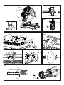
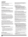
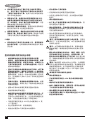
C. Spark Deflector
D. Base
E. Fence
F. Vise
G. Hexagon Wrench
H. Crank
I. Vise Level
J. Wheel
K. Guard
L. Spindle Lock
M. Depth Stop Bolt and Jam Nut
N. Trigger Switch with Lock on
O. Padlock Hole
P. Fence Bolts
X. Lock Pin
POWER SUPPLY
Be sure your power supply agrees with the nameplate
marking. A voltage decrease of more than 10% willcause a
loss of power and overheating.
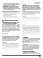
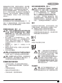
CUTTING CAPACITY
The wide vise opening and high pivot point provide cutting
capacity for many large pieces. Use the cutting capacity chart
to determine total maximum size of cuts that can be made
with a new wheel.
CAUTION: CERTAIN LARGE, CIRCULAR OR IRREGU-
LARLY SHAPED OBJECTS MAY REQUIRE ADDITIONAL
HOLDING MEANS IF THEY CANNOT BE HELD
SECURELY IN VISE.
CAUTION: DO NOT CUT MAGNESIUM WITH THIS TOOL.
Maximum Cutting Capacity
NOTE: Capacity shown on chart assumes no wheel wear and
optimum fence position.
USE
Standard Equipment
• 355mm Metal Cutting Abrasive Wheel
• 1 Wheel Wrench
• 1 Instruction manual
WARNING SYMBOLS
The label on your tool may include the following
symbols:
.......................Use Eye Protection
.......................Use Ear Protection
V .......................Volts
A .......................Amperes
Hz .......................Hertz
W .......................Watts
min.......................minutes
.......................Alternating current
.......................Direct current
n
0
.......................No load speed
.......................Class II Construction
.......................Earthing terminal
.......................Safety alert symbol
.../min...................
Revolutions or reciprocationsper minute
ELECTRICAL SAFETY
Warning! If the power cord is damaged, it must be
replaced by the manufacturer, authorizedStanley Service
Center or an equally qualified person in order to avoid
damage or injury.If the power cord is replaced by an equally
qualified person, but not authorized by Stanley, the warranty
will not be valid.
LABELS ON TOOL
The label on your tool may include the following symbols along
with the date code:
FEATURES (fig. 1, 4)
A. Lock on Button
B. Spark Deflector Screw
A x B
Workpiece
Shape:
90°
Cutting Angle
45°
Cutting Angle
A = 4-7/8"
(125mm)
A= 4-1/2"
(115mm)
A = 4-1/2"
(115mm)
A = 3-13/16"
(98mm)
4-1/2" x 5-1/8"
(115mm x 130mm)
4" x 7-5/8"
(102mm x 188mm)
3" x 7-3/8"
(76mm x 229mm)
4-1/2" x 4-1/8"
(115mm x 105mm)
A = 4-1/2"
(115mm)
A = 5-3/8"
(137mm)
WARNING: To reduce the risk of injury, the
user must read the instruction manual.
Use Eye Protection.
Use Ear Protection.
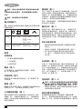
POSITION OF DATE CODE
The Date Code, which also includes the year of
manufacture, is printed into the housing.
Example:
2016 XX JN
Year of manufacturing
To Carry (fig. 1)
Fold down unit to position where you can carry the saw.
Push in lock pin (X) to lock arm down.
Installation Instruction (fig. 3)
Fix the tool on a stable position through fix holes by using 2
M10 bolts.
UnLocking (fig. 1)
To unlock tool and raise head, depress motor arm slightly
and pull lock pin (X) out. Motor arm will then pivot upward.
Spark Deflector Adjustment (fig. 1)
To best deflect sparks away from surrounding persons and
materials, loosen the screw (B), adjust the spark deflector
(C) and then retighten screw. Do not allow cordset to come
into contact with deflector or sparks as damage to cordset
may occur.
Depth Stop (fig. 1)
Depth stop is set at the factory for a new 14" wheel to
prevent wheel from cutting into the supporting surface.To
allow more depth of cut, use the hexagon wrench provided
(G) to loosen the depth stop bolt (M) and raise bolt todesired
height and then turn jam nut (M) clockwise until seated firmly
on the casting. Securely tighten the depth stop bolt before use.
CAUTION: When changing to a new wheel, readjust
depth stop to original position to prevent cutting
intosupporting surface.
Trigger Switch with Lock-on(fig. 1)
To start the tool, depress the trigger switch (N), then push
lockon button to keep tool running. To turn the tool off,
depress the trigger again and release the trigger switch.
Keep hands and material from wheel until it has coasted to
a stop.To prevent unauthorized use of tool, install a tandard
padlock (not included) into the padlock hole (O) located in
the trigger.
Material Clamping and Supporting
• Angles are best clamped and cut with both legs resting
against base.
• A spacer block slightly narrower than the work piece
can be used to increase wheel utilization (Fig. 2).
• Long work pieces must be supported by a block so it
will be level with top of base (Fig. 3). The cut off end
should be free to fall downward to avoid wheel
binding.
Vise Operation (fig. 4)
The vise (F) has a quick-travel feature. To release the vise
when it is clamped tightly, turn the crank (H)
counter-clockwise one or two times to remove clamping
pressure. Lift vise lever (I) up. Pull crank assembly out as
far asdesired. Vise may be pushed forward into work
without cranking. Lower vise lever (I) then tighten vise (F)
onwork by using crank (H).
Fence Operation (fig. 5, 6)
CAUTION:
Turn off and unplug the tool before
making any adjustments or removing or
installing attachments or accessories. Be sure
the trigger switch is in the OFF position.The fence
(E) can be adjusted two ways: to change desired
cutting angle and to change spacing between the fence
and vise.
To Change the Desired Cutting Angle
Use the wrench provided to loosen (do not remove) the two
fence bolts (P). Align the desired angle indicator line with
theslot line (Q) in the base (D). Securely tighten both fence
bolts before use. For more accurate square cuts,
disconnect the power supply, loosen the two fence bolts,
push arm down until wheel extends into base. Place a
square against thewheel and adjust fence against the
square. Securely tighten both fence bolts before use. When
making a miter cut, the vise (F) may not clamp securely,
depending on the thickness of the workpiece and the miter
angle. Other aids (such as spring, bar or C-clamps) will
benecessary to secure the work piece to the fence when
making these cuts.
To Change Spacing between The Fence and Vise
Using the wrench provided, loosen and remove the two
fence bolts (P). Adjust the fence (E) to desired locations.In-
sert both fence bolts in provided locations. Securely tighten
both fence bolts before use.
Removal and Installation of Wheels (fig. 7, 8)
CAUTION: Turn off and unplug the tool before
making any adjustments or removing or installin
gattachments or accessories. Be sure the trigger
switch is in the OFF position. Do not make any
adjustment while the wheel is in motion. Do not make
any adjustment while chop saw is plugged into power supply.
1. Push in spindle lock (L) and rotate wheel (J) by hand
until wheel lock lever engages slot in inside flange(R) to
lock wheel. Loosen the bolt (S) counterclockwise in the
center of the abrasive wheel with the 8mm hex wrench
(G). Bolt has right-hand thread.
2. Remove the bolt (S), washer (T), outside flange (U) and
old wheel (J).
3. Make sure flange surfaces are clean and flat. Install the
new abrasive wheel by reversing the above steps.
4. Do not overtighten bolt.
WARNING: Check the work surface that the chop saw
rests on when replacing with a new abrasive wheel. Itis
possible that the wheel may contact ANY ITEMS OR
STRUCTURE THAT EXTENDS ABOVE work surface (under
the base) when the arm is fully lowered.
WARNING: Always keep the screw attached to the
guard and make sure the center guard in the right
position after replacing wheel and before use, to protect
user from high speed rotating wheel.
OPERATION TIPS FOR MORE ACCURATE CUTS
• Allow the wheel to do the cutting. Excessive force will
cause the wheel to glaze reducing cutting efficiency
and/or to deflect causing inaccurate cuts.
• Properly adjust fence angle.
• Make sure material is laying flat across base.
• Properly clamp material to avoid movement and
vibration.
MOTOR BRUSH INSPECTION AND REPLACEMENT
(FIG.9)
WARNING:Turn off and unplug the tool. Be sure
the trigger switch is in the OFF position.
Brushes should be regularly inspected for wear. To inspect
brushes, unscrew the two end cap screws (V) and remove
end cap (W). Remove brush cap (Y). Brushes (Z) should slide
freely in brush box. If brushes are worndown to .3" (8mm)
as shown in Figure 9 they should be replaced. To reinstall,
push new brush back into brushbox. If replacing existing
brush, maintain same orientation as when removed. Replace
the brush cap (do not overtighten). Replace end cap and two
screws. Tighten securely.
MAINTENANCE
Your Stanley power tool has been designed to operate over
a long period of time with a minimum of maintenance.Con-
tinuous satisfactory operation depends upon proper tool
care and regular cleaning.Your tool is not user-serviceable.
Take the tool to an authorized Stanley repair agent. This
tool should be serviced at regular intervals or when
showing a noticeable change in performance.
Lubrication
Stanley power tools are properly lubricated at the factory
and are ready for use. Tools should be re-lubricated
regularly , depending on usage. This lubrication should
only be attempted by trained power tool repair persons,
such as those at Stanley service centers or by other
qualified service personnel.
Closed-type, grease-sealed ball bearings are used
throughout. These bearings have sufficient lubrication-
packed in them at the factory to last the life of the chop
saw.
Cleaning
Warning:
unplug the tool before you use a cloth to
clean the housing.With the motor running, blow dirt and
dust out of all air vents with dry air at least once a week.
Wear safety glasses when performing this. Exterior plastic
parts may be cleaned with a damp cloth and mild detergent.
Although these parts are highly solvent resistant, NEVER use
solvents.
Blowing dust and grit out of the main housing by means of
an air hose is recommended and may be done as often as
dirt is seen collecting in and around the air vents. Always
wear proper eye and respiratory protection.
Tool Care
Avoid overloading the machine.Overloading will result in a
considerable reduction in speed and efficiency and the unit
will become hot. In this event,run the machine at no load
for a minute or two until cooled to normal working
temperature by the built in fan. Switching your machine on
and off whilst under load will considerably reduce the life of
the switch.
Important
To ensure product SAFETY and RELIABILITY, repairs,
maintenance and adjustment (other than those listed in this
manual) should be performed by authorized service centers
or other qualified organizations, always-using identical
replacement parts. Unit contains no user serviceable parts
inside.Blowing dust and grit out of the main housing by
means of an air hose is recommended and may be done as
often as dirt is seen collecting in and around the air vents.
Always wear proper eye and respiratory protection.
NOTE: Unit may be converted to a 3-wire twist lock cord set
at an authorized service center.
ACCESSORIES
The performance of any power tool is dependent upon the
accessory used. Stanley accessories areengineered to high
quality standards and are designed to enhance the
performance of power tool.
Note:
Accessory must be rated for use at speed equal to or
higher than nameplate RPM of tool with which it is being
used.
CAUTION
: The use of any other accessory not
recommended for use with this tool could be hazardous.Use
only high-strength Type 1 organic bonded wheels rated
4100 rpm or higher. Recommended accessories for use
with your tool are available at extra cost from your local
dealer or authorized service center.
Protecting The Environment
Should you find one day that your tool needs
replacement, or if it is of no further use to you, think of
theprotection of the environment. Stanley recommends
you to contact your local council for disposal
information.
Service Information
Stanley offers a full network of company-owned and
authorized service locations throughout Asia. All Stanley
Service Centers are staffed with trained personnel to
provide customers with efficient and reliable power tool
service.Whether you need technical advice, repair, or
genuine factory replacement parts, contact the Stanley
location nearest to you.
Notes
Stanley's policy is one of continuous improvement to
our products and, as such, we reserve the right
tochange product specifications without prior notice.
Standard equipment and accessories may vary by
country.
Product specifications may differ by country.
Complete product range may not be available in all
countries.
Contact your local Stanley dealers for range availability.

C. Spark Deflector
D. Base
E. Fence
F. Vise
G. Hexagon Wrench
H. Crank
I. Vise Level
J. Wheel
K. Guard
L. Spindle Lock
M. Depth Stop Bolt and Jam Nut
N. Trigger Switch with Lock on
O. Padlock Hole
P. Fence Bolts
X. Lock Pin
POWER SUPPLY
Be sure your power supply agrees with the nameplate
marking. A voltage decrease of more than 10% willcause a
loss of power and overheating.
CUTTING CAPACITY
The wide vise opening and high pivot point provide cutting
capacity for many large pieces. Use the cutting capacity chart
to determine total maximum size of cuts that can be made
with a new wheel.
CAUTION: CERTAIN LARGE, CIRCULAR OR IRREGU-
LARLY SHAPED OBJECTS MAY REQUIRE ADDITIONAL
HOLDING MEANS IF THEY CANNOT BE HELD
SECURELY IN VISE.
CAUTION: DO NOT CUT MAGNESIUM WITH THIS TOOL.
Maximum Cutting Capacity
NOTE: Capacity shown on chart assumes no wheel wear and
optimum fence position.
USE
Standard Equipment
• 355mm Metal Cutting Abrasive Wheel
• 1 Wheel Wrench
• 1 Instruction manual
WARNING SYMBOLS
The label on your tool may include the following
symbols:
.......................Use Eye Protection
.......................Use Ear Protection
V .......................Volts
A .......................Amperes
Hz .......................Hertz
W .......................Watts
min.......................minutes
.......................Alternating current
.......................Direct current
n
0
.......................No load speed
.......................Class II Construction
.......................Earthing terminal
.......................Safety alert symbol
.../min...................
Revolutions or reciprocationsper minute
ELECTRICAL SAFETY
Warning! If the power cord is damaged, it must be
replaced by the manufacturer, authorizedStanley Service
Center or an equally qualified person in order to avoid
damage or injury.If the power cord is replaced by an equally
qualified person, but not authorized by Stanley, the warranty
will not be valid.
LABELS ON TOOL
The label on your tool may include the following symbols along
with the date code:
FEATURES (fig. 1, 4)
A. Lock on Button
B. Spark Deflector Screw
6
ENGLISH
To Carry (fig. 1)
Fold down unit to position where you can carry the saw.
Push in lock pin (X) to lock arm down.
Installation Instruction (fig. 3)
Fix the tool on a stable position through fix holes by using 2
M10 bolts.
UnLocking (fig. 1)
To unlock tool and raise head, depress motor arm slightly
and pull lock pin (X) out. Motor arm will then pivot upward.
Spark Deflector Adjustment (fig. 1)
To best deflect sparks away from surrounding persons and
materials, loosen the screw (B), adjust the spark deflector
(C) and then retighten screw. Do not allow cordset to come
into contact with deflector or sparks as damage to cordset
may occur.
Depth Stop (fig. 1)
Depth stop is set at the factory for a new 14" wheel to
prevent wheel from cutting into the supporting surface.To
allow more depth of cut, use the hexagon wrench provided
(G) to loosen the depth stop bolt (M) and raise bolt todesired
height and then turn jam nut (M) clockwise until seated firmly
on the casting. Securely tighten the depth stop bolt before use.
CAUTION: When changing to a new wheel, readjust
depth stop to original position to prevent cutting
intosupporting surface.
Trigger Switch with Lock-on(fig. 1)
To start the tool, depress the trigger switch (N), then push
lockon button to keep tool running. To turn the tool off,
depress the trigger again and release the trigger switch.
Keep hands and material from wheel until it has coasted to
a stop.To prevent unauthorized use of tool, install a tandard
padlock (not included) into the padlock hole (O) located in
the trigger.
Material Clamping and Supporting
• Angles are best clamped and cut with both legs resting
against base.
• A spacer block slightly narrower than the work piece
can be used to increase wheel utilization (Fig. 2).
• Long work pieces must be supported by a block so it
will be level with top of base (Fig. 3). The cut off end
should be free to fall downward to avoid wheel
binding.
Vise Operation (fig. 4)
The vise (F) has a quick-travel feature. To release the vise
when it is clamped tightly, turn the crank (H)
counter-clockwise one or two times to remove clamping
pressure. Lift vise lever (I) up. Pull crank assembly out as
far asdesired. Vise may be pushed forward into work
without cranking. Lower vise lever (I) then tighten vise (F)
onwork by using crank (H).
Fence Operation (fig. 5, 6)
CAUTION:
Turn off and unplug the tool before
making any adjustments or removing or
installing attachments or accessories. Be sure
the trigger switch is in the OFF position.The fence
(E) can be adjusted two ways: to change desired
cutting angle and to change spacing between the fence
and vise.
To Change the Desired Cutting Angle
Use the wrench provided to loosen (do not remove) the two
fence bolts (P). Align the desired angle indicator line with
theslot line (Q) in the base (D). Securely tighten both fence
bolts before use. For more accurate square cuts,
disconnect the power supply, loosen the two fence bolts,
push arm down until wheel extends into base. Place a
square against thewheel and adjust fence against the
square. Securely tighten both fence bolts before use. When
making a miter cut, the vise (F) may not clamp securely,
depending on the thickness of the workpiece and the miter
angle. Other aids (such as spring, bar or C-clamps) will
benecessary to secure the work piece to the fence when
making these cuts.
To Change Spacing between The Fence and Vise
Using the wrench provided, loosen and remove the two
fence bolts (P). Adjust the fence (E) to desired locations.In-
sert both fence bolts in provided locations. Securely tighten
both fence bolts before use.
Removal and Installation of Wheels (fig. 7, 8)
CAUTION: Turn off and unplug the tool before
making any adjustments or removing or installin
gattachments or accessories. Be sure the trigger
switch is in the OFF position. Do not make any
adjustment while the wheel is in motion. Do not make
any adjustment while chop saw is plugged into power supply.
1. Push in spindle lock (L) and rotate wheel (J) by hand
until wheel lock lever engages slot in inside flange(R) to
lock wheel. Loosen the bolt (S) counterclockwise in the
center of the abrasive wheel with the 8mm hex wrench
(G). Bolt has right-hand thread.
2. Remove the bolt (S), washer (T), outside flange (U) and
old wheel (J).
3. Make sure flange surfaces are clean and flat. Install the
new abrasive wheel by reversing the above steps.
4. Do not overtighten bolt.
WARNING: Check the work surface that the chop saw
rests on when replacing with a new abrasive wheel. Itis
possible that the wheel may contact ANY ITEMS OR
STRUCTURE THAT EXTENDS ABOVE work surface (under
the base) when the arm is fully lowered.
WARNING: Always keep the screw attached to the
guard and make sure the center guard in the right
position after replacing wheel and before use, to protect
user from high speed rotating wheel.
OPERATION TIPS FOR MORE ACCURATE CUTS
• Allow the wheel to do the cutting. Excessive force will
cause the wheel to glaze reducing cutting efficiency
and/or to deflect causing inaccurate cuts.
• Properly adjust fence angle.
• Make sure material is laying flat across base.
• Properly clamp material to avoid movement and
vibration.
MOTOR BRUSH INSPECTION AND REPLACEMENT
(FIG.9)
WARNING:Turn off and unplug the tool. Be sure
the trigger switch is in the OFF position.
Brushes should be regularly inspected for wear. To inspect
brushes, unscrew the two end cap screws (V) and remove
end cap (W). Remove brush cap (Y). Brushes (Z) should slide
freely in brush box. If brushes are worndown to .3" (8mm)
as shown in Figure 9 they should be replaced. To reinstall,
push new brush back into brushbox. If replacing existing
brush, maintain same orientation as when removed. Replace
the brush cap (do not overtighten). Replace end cap and two
screws. Tighten securely.
MAINTENANCE
Your Stanley power tool has been designed to operate over
a long period of time with a minimum of maintenance.Con-
tinuous satisfactory operation depends upon proper tool
care and regular cleaning.Your tool is not user-serviceable.
Take the tool to an authorized Stanley repair agent. This
tool should be serviced at regular intervals or when
showing a noticeable change in performance.
Lubrication
Stanley power tools are properly lubricated at the factory
and are ready for use. Tools should be re-lubricated
regularly , depending on usage. This lubrication should
only be attempted by trained power tool repair persons,
such as those at Stanley service centers or by other
qualified service personnel.
Closed-type, grease-sealed ball bearings are used
throughout. These bearings have sufficient lubrication-
packed in them at the factory to last the life of the chop
saw.
Cleaning
Warning:
unplug the tool before you use a cloth to
clean the housing.With the motor running, blow dirt and
dust out of all air vents with dry air at least once a week.
Wear safety glasses when performing this. Exterior plastic
parts may be cleaned with a damp cloth and mild detergent.
Although these parts are highly solvent resistant, NEVER use
solvents.
Blowing dust and grit out of the main housing by means of
an air hose is recommended and may be done as often as
dirt is seen collecting in and around the air vents. Always
wear proper eye and respiratory protection.
Tool Care
Avoid overloading the machine.Overloading will result in a
considerable reduction in speed and efficiency and the unit
will become hot. In this event,run the machine at no load
for a minute or two until cooled to normal working
temperature by the built in fan. Switching your machine on
and off whilst under load will considerably reduce the life of
the switch.
Important
To ensure product SAFETY and RELIABILITY, repairs,
maintenance and adjustment (other than those listed in this
manual) should be performed by authorized service centers
or other qualified organizations, always-using identical
replacement parts. Unit contains no user serviceable parts
inside.Blowing dust and grit out of the main housing by
means of an air hose is recommended and may be done as
often as dirt is seen collecting in and around the air vents.
Always wear proper eye and respiratory protection.
NOTE: Unit may be converted to a 3-wire twist lock cord set
at an authorized service center.
ACCESSORIES
The performance of any power tool is dependent upon the
accessory used. Stanley accessories areengineered to high
quality standards and are designed to enhance the
performance of power tool.
Note:
Accessory must be rated for use at speed equal to or
higher than nameplate RPM of tool with which it is being
used.
CAUTION
: The use of any other accessory not
recommended for use with this tool could be hazardous.Use
only high-strength Type 1 organic bonded wheels rated
4100 rpm or higher. Recommended accessories for use
with your tool are available at extra cost from your local
dealer or authorized service center.
Protecting The Environment
Should you find one day that your tool needs
replacement, or if it is of no further use to you, think of
theprotection of the environment. Stanley recommends
you to contact your local council for disposal
information.
Service Information
Stanley offers a full network of company-owned and
authorized service locations throughout Asia. All Stanley
Service Centers are staffed with trained personnel to
provide customers with efficient and reliable power tool
service.Whether you need technical advice, repair, or
genuine factory replacement parts, contact the Stanley
location nearest to you.
Notes
Stanley's policy is one of continuous improvement to
our products and, as such, we reserve the right
tochange product specifications without prior notice.
Standard equipment and accessories may vary by
country.
Product specifications may differ by country.
Complete product range may not be available in all
countries.
Contact your local Stanley dealers for range availability.

C. Spark Deflector
D. Base
E. Fence
F. Vise
G. Hexagon Wrench
H. Crank
I. Vise Level
J. Wheel
K. Guard
L. Spindle Lock
M. Depth Stop Bolt and Jam Nut
N. Trigger Switch with Lock on
O. Padlock Hole
P. Fence Bolts
X. Lock Pin
POWER SUPPLY
Be sure your power supply agrees with the nameplate
marking. A voltage decrease of more than 10% willcause a
loss of power and overheating.
CUTTING CAPACITY
The wide vise opening and high pivot point provide cutting
capacity for many large pieces. Use the cutting capacity chart
to determine total maximum size of cuts that can be made
with a new wheel.
CAUTION: CERTAIN LARGE, CIRCULAR OR IRREGU-
LARLY SHAPED OBJECTS MAY REQUIRE ADDITIONAL
HOLDING MEANS IF THEY CANNOT BE HELD
SECURELY IN VISE.
CAUTION: DO NOT CUT MAGNESIUM WITH THIS TOOL.
Maximum Cutting Capacity
NOTE: Capacity shown on chart assumes no wheel wear and
optimum fence position.
USE
Standard Equipment
• 355mm Metal Cutting Abrasive Wheel
• 1 Wheel Wrench
• 1 Instruction manual
WARNING SYMBOLS
The label on your tool may include the following
symbols:
.......................Use Eye Protection
.......................Use Ear Protection
V .......................Volts
A .......................Amperes
Hz .......................Hertz
W .......................Watts
min.......................minutes
.......................Alternating current
.......................Direct current
n
0
.......................No load speed
.......................Class II Construction
.......................Earthing terminal
.......................Safety alert symbol
.../min...................
Revolutions or reciprocationsper minute
ELECTRICAL SAFETY
Warning! If the power cord is damaged, it must be
replaced by the manufacturer, authorizedStanley Service
Center or an equally qualified person in order to avoid
damage or injury.If the power cord is replaced by an equally
qualified person, but not authorized by Stanley, the warranty
will not be valid.
LABELS ON TOOL
The label on your tool may include the following symbols along
with the date code:
FEATURES (fig. 1, 4)
A. Lock on Button
B. Spark Deflector Screw
7
ENGLISH
To Carry (fig. 1)
Fold down unit to position where you can carry the saw.
Push in lock pin (X) to lock arm down.
Installation Instruction (fig. 3)
Fix the tool on a stable position through fix holes by using 2
M10 bolts.
UnLocking (fig. 1)
To unlock tool and raise head, depress motor arm slightly
and pull lock pin (X) out. Motor arm will then pivot upward.
Spark Deflector Adjustment (fig. 1)
To best deflect sparks away from surrounding persons and
materials, loosen the screw (B), adjust the spark deflector
(C) and then retighten screw. Do not allow cordset to come
into contact with deflector or sparks as damage to cordset
may occur.
Depth Stop (fig. 1)
Depth stop is set at the factory for a new 14" wheel to
prevent wheel from cutting into the supporting surface.To
allow more depth of cut, use the hexagon wrench provided
(G) to loosen the depth stop bolt (M) and raise bolt todesired
height and then turn jam nut (M) clockwise until seated firmly
on the casting. Securely tighten the depth stop bolt before use.
CAUTION: When changing to a new wheel, readjust
depth stop to original position to prevent cutting
intosupporting surface.
Trigger Switch with Lock-on(fig. 1)
To start the tool, depress the trigger switch (N), then push
lockon button to keep tool running. To turn the tool off,
depress the trigger again and release the trigger switch.
Keep hands and material from wheel until it has coasted to
a stop.To prevent unauthorized use of tool, install a tandard
padlock (not included) into the padlock hole (O) located in
the trigger.
Material Clamping and Supporting
• Angles are best clamped and cut with both legs resting
against base.
• A spacer block slightly narrower than the work piece
can be used to increase wheel utilization (Fig. 2).
• Long work pieces must be supported by a block so it
will be level with top of base (Fig. 3). The cut off end
should be free to fall downward to avoid wheel
binding.
Vise Operation (fig. 4)
The vise (F) has a quick-travel feature. To release the vise
when it is clamped tightly, turn the crank (H)
counter-clockwise one or two times to remove clamping
pressure. Lift vise lever (I) up. Pull crank assembly out as
far asdesired. Vise may be pushed forward into work
without cranking. Lower vise lever (I) then tighten vise (F)
onwork by using crank (H).
Fence Operation (fig. 5, 6)
CAUTION:
Turn off and unplug the tool before
making any adjustments or removing or
installing attachments or accessories. Be sure
the trigger switch is in the OFF position.The fence
(E) can be adjusted two ways: to change desired
cutting angle and to change spacing between the fence
and vise.
To Change the Desired Cutting Angle
Use the wrench provided to loosen (do not remove) the two
fence bolts (P). Align the desired angle indicator line with
theslot line (Q) in the base (D). Securely tighten both fence
bolts before use. For more accurate square cuts,
disconnect the power supply, loosen the two fence bolts,
push arm down until wheel extends into base. Place a
square against thewheel and adjust fence against the
square. Securely tighten both fence bolts before use. When
making a miter cut, the vise (F) may not clamp securely,
depending on the thickness of the workpiece and the miter
angle. Other aids (such as spring, bar or C-clamps) will
benecessary to secure the work piece to the fence when
making these cuts.
To Change Spacing between The Fence and Vise
Using the wrench provided, loosen and remove the two
fence bolts (P). Adjust the fence (E) to desired locations.In-
sert both fence bolts in provided locations. Securely tighten
both fence bolts before use.
Removal and Installation of Wheels (fig. 7, 8)
CAUTION: Turn off and unplug the tool before
making any adjustments or removing or installin
gattachments or accessories. Be sure the trigger
switch is in the OFF position. Do not make any
adjustment while the wheel is in motion. Do not make
any adjustment while chop saw is plugged into power supply.
1. Push in spindle lock (L) and rotate wheel (J) by hand
until wheel lock lever engages slot in inside flange(R) to
lock wheel. Loosen the bolt (S) counterclockwise in the
center of the abrasive wheel with the 8mm hex wrench
(G). Bolt has right-hand thread.
2. Remove the bolt (S), washer (T), outside flange (U) and
old wheel (J).
3. Make sure flange surfaces are clean and flat. Install the
new abrasive wheel by reversing the above steps.
4. Do not overtighten bolt.
WARNING: Check the work surface that the chop saw
rests on when replacing with a new abrasive wheel. Itis
possible that the wheel may contact ANY ITEMS OR
STRUCTURE THAT EXTENDS ABOVE work surface (under
the base) when the arm is fully lowered.
WARNING: Always keep the screw attached to the
guard and make sure the center guard in the right
position after replacing wheel and before use, to protect
user from high speed rotating wheel.
OPERATION TIPS FOR MORE ACCURATE CUTS
• Allow the wheel to do the cutting. Excessive force will
cause the wheel to glaze reducing cutting efficiency
and/or to deflect causing inaccurate cuts.
• Properly adjust fence angle.
• Make sure material is laying flat across base.
• Properly clamp material to avoid movement and
vibration.
MOTOR BRUSH INSPECTION AND REPLACEMENT
(FIG.9)
WARNING:Turn off and unplug the tool. Be sure
the trigger switch is in the OFF position.
Brushes should be regularly inspected for wear. To inspect
brushes, unscrew the two end cap screws (V) and remove
end cap (W). Remove brush cap (Y). Brushes (Z) should slide
freely in brush box. If brushes are worndown to .3" (8mm)
as shown in Figure 9 they should be replaced. To reinstall,
push new brush back into brushbox. If replacing existing
brush, maintain same orientation as when removed. Replace
the brush cap (do not overtighten). Replace end cap and two
screws. Tighten securely.
MAINTENANCE
Your Stanley power tool has been designed to operate over
a long period of time with a minimum of maintenance.Con-
tinuous satisfactory operation depends upon proper tool
care and regular cleaning.Your tool is not user-serviceable.
Take the tool to an authorized Stanley repair agent. This
tool should be serviced at regular intervals or when
showing a noticeable change in performance.
Lubrication
Stanley power tools are properly lubricated at the factory
and are ready for use. Tools should be re-lubricated
regularly , depending on usage. This lubrication should
only be attempted by trained power tool repair persons,
such as those at Stanley service centers or by other
qualified service personnel.
Closed-type, grease-sealed ball bearings are used
throughout. These bearings have sufficient lubrication-
packed in them at the factory to last the life of the chop
saw.
Cleaning
Warning:
unplug the tool before you use a cloth to
clean the housing.With the motor running, blow dirt and
dust out of all air vents with dry air at least once a week.
Wear safety glasses when performing this. Exterior plastic
parts may be cleaned with a damp cloth and mild detergent.
Although these parts are highly solvent resistant, NEVER use
solvents.
Blowing dust and grit out of the main housing by means of
an air hose is recommended and may be done as often as
dirt is seen collecting in and around the air vents. Always
wear proper eye and respiratory protection.
Tool Care
Avoid overloading the machine.Overloading will result in a
considerable reduction in speed and efficiency and the unit
will become hot. In this event,run the machine at no load
for a minute or two until cooled to normal working
temperature by the built in fan. Switching your machine on
and off whilst under load will considerably reduce the life of
the switch.
Important
To ensure product SAFETY and RELIABILITY, repairs,
maintenance and adjustment (other than those listed in this
manual) should be performed by authorized service centers
or other qualified organizations, always-using identical
replacement parts. Unit contains no user serviceable parts
inside.Blowing dust and grit out of the main housing by
means of an air hose is recommended and may be done as
often as dirt is seen collecting in and around the air vents.
Always wear proper eye and respiratory protection.
NOTE: Unit may be converted to a 3-wire twist lock cord set
at an authorized service center.
ACCESSORIES
The performance of any power tool is dependent upon the
accessory used. Stanley accessories areengineered to high
quality standards and are designed to enhance the
performance of power tool.
Note:
Accessory must be rated for use at speed equal to or
higher than nameplate RPM of tool with which it is being
used.
CAUTION
: The use of any other accessory not
recommended for use with this tool could be hazardous.Use
only high-strength Type 1 organic bonded wheels rated
4100 rpm or higher. Recommended accessories for use
with your tool are available at extra cost from your local
dealer or authorized service center.
Protecting The Environment
Should you find one day that your tool needs
replacement, or if it is of no further use to you, think of
theprotection of the environment. Stanley recommends
you to contact your local council for disposal
information.
Service Information
Stanley offers a full network of company-owned and
authorized service locations throughout Asia. All Stanley
Service Centers are staffed with trained personnel to
provide customers with efficient and reliable power tool
service.Whether you need technical advice, repair, or
genuine factory replacement parts, contact the Stanley
location nearest to you.
Notes
Stanley's policy is one of continuous improvement to
our products and, as such, we reserve the right
tochange product specifications without prior notice.
Standard equipment and accessories may vary by
country.
Product specifications may differ by country.
Complete product range may not be available in all
countries.
Contact your local Stanley dealers for range availability.

C. Spark Deflector
D. Base
E. Fence
F. Vise
G. Hexagon Wrench
H. Crank
I. Vise Level
J. Wheel
K. Guard
L. Spindle Lock
M. Depth Stop Bolt and Jam Nut
N. Trigger Switch with Lock on
O. Padlock Hole
P. Fence Bolts
X. Lock Pin
POWER SUPPLY
Be sure your power supply agrees with the nameplate
marking. A voltage decrease of more than 10% willcause a
loss of power and overheating.
CUTTING CAPACITY
The wide vise opening and high pivot point provide cutting
capacity for many large pieces. Use the cutting capacity chart
to determine total maximum size of cuts that can be made
with a new wheel.
CAUTION: CERTAIN LARGE, CIRCULAR OR IRREGU-
LARLY SHAPED OBJECTS MAY REQUIRE ADDITIONAL
HOLDING MEANS IF THEY CANNOT BE HELD
SECURELY IN VISE.
CAUTION: DO NOT CUT MAGNESIUM WITH THIS TOOL.
Maximum Cutting Capacity
NOTE: Capacity shown on chart assumes no wheel wear and
optimum fence position.
USE
Standard Equipment
• 355mm Metal Cutting Abrasive Wheel
• 1 Wheel Wrench
• 1 Instruction manual
WARNING SYMBOLS
The label on your tool may include the following
symbols:
.......................Use Eye Protection
.......................Use Ear Protection
V .......................Volts
A .......................Amperes
Hz .......................Hertz
W .......................Watts
min.......................minutes
.......................Alternating current
.......................Direct current
n
0
.......................No load speed
.......................Class II Construction
.......................Earthing terminal
.......................Safety alert symbol
.../min...................
Revolutions or reciprocationsper minute
ELECTRICAL SAFETY
Warning! If the power cord is damaged, it must be
replaced by the manufacturer, authorizedStanley Service
Center or an equally qualified person in order to avoid
damage or injury.If the power cord is replaced by an equally
qualified person, but not authorized by Stanley, the warranty
will not be valid.
LABELS ON TOOL
The label on your tool may include the following symbols along
with the date code:
FEATURES (fig. 1, 4)
A. Lock on Button
B. Spark Deflector Screw
8
ENGLISH
To Carry (fig. 1)
Fold down unit to position where you can carry the saw.
Push in lock pin (X) to lock arm down.
Installation Instruction (fig. 3)
Fix the tool on a stable position through fix holes by using 2
M10 bolts.
UnLocking (fig. 1)
To unlock tool and raise head, depress motor arm slightly
and pull lock pin (X) out. Motor arm will then pivot upward.
Spark Deflector Adjustment (fig. 1)
To best deflect sparks away from surrounding persons and
materials, loosen the screw (B), adjust the spark deflector
(C) and then retighten screw. Do not allow cordset to come
into contact with deflector or sparks as damage to cordset
may occur.
Depth Stop (fig. 1)
Depth stop is set at the factory for a new 14" wheel to
prevent wheel from cutting into the supporting surface.To
allow more depth of cut, use the hexagon wrench provided
(G) to loosen the depth stop bolt (M) and raise bolt todesired
height and then turn jam nut (M) clockwise until seated firmly
on the casting. Securely tighten the depth stop bolt before use.
CAUTION: When changing to a new wheel, readjust
depth stop to original position to prevent cutting
intosupporting surface.
Trigger Switch with Lock-on(fig. 1)
To start the tool, depress the trigger switch (N), then push
lockon button to keep tool running. To turn the tool off,
depress the trigger again and release the trigger switch.
Keep hands and material from wheel until it has coasted to
a stop.To prevent unauthorized use of tool, install a tandard
padlock (not included) into the padlock hole (O) located in
the trigger.
Material Clamping and Supporting
• Angles are best clamped and cut with both legs resting
against base.
• A spacer block slightly narrower than the work piece
can be used to increase wheel utilization (Fig. 2).
• Long work pieces must be supported by a block so it
will be level with top of base (Fig. 3). The cut off end
should be free to fall downward to avoid wheel
binding.
Vise Operation (fig. 4)
The vise (F) has a quick-travel feature. To release the vise
when it is clamped tightly, turn the crank (H)
counter-clockwise one or two times to remove clamping
pressure. Lift vise lever (I) up. Pull crank assembly out as
far asdesired. Vise may be pushed forward into work
without cranking. Lower vise lever (I) then tighten vise (F)
onwork by using crank (H).
Fence Operation (fig. 5, 6)
CAUTION:
Turn off and unplug the tool before
making any adjustments or removing or
installing attachments or accessories. Be sure
the trigger switch is in the OFF position.The fence
(E) can be adjusted two ways: to change desired
cutting angle and to change spacing between the fence
and vise.
To Change the Desired Cutting Angle
Use the wrench provided to loosen (do not remove) the two
fence bolts (P). Align the desired angle indicator line with
theslot line (Q) in the base (D). Securely tighten both fence
bolts before use. For more accurate square cuts,
disconnect the power supply, loosen the two fence bolts,
push arm down until wheel extends into base. Place a
square against thewheel and adjust fence against the
square. Securely tighten both fence bolts before use. When
making a miter cut, the vise (F) may not clamp securely,
depending on the thickness of the workpiece and the miter
angle. Other aids (such as spring, bar or C-clamps) will
benecessary to secure the work piece to the fence when
making these cuts.
To Change Spacing between The Fence and Vise
Using the wrench provided, loosen and remove the two
fence bolts (P). Adjust the fence (E) to desired locations.In-
sert both fence bolts in provided locations. Securely tighten
both fence bolts before use.
Removal and Installation of Wheels (fig. 7, 8)
CAUTION: Turn off and unplug the tool before
making any adjustments or removing or installin
gattachments or accessories. Be sure the trigger
switch is in the OFF position. Do not make any
adjustment while the wheel is in motion. Do not make
any adjustment while chop saw is plugged into power supply.
1. Push in spindle lock (L) and rotate wheel (J) by hand
until wheel lock lever engages slot in inside flange(R) to
lock wheel. Loosen the bolt (S) counterclockwise in the
center of the abrasive wheel with the 8mm hex wrench
(G). Bolt has right-hand thread.
2. Remove the bolt (S), washer (T), outside flange (U) and
old wheel (J).
3. Make sure flange surfaces are clean and flat. Install the
new abrasive wheel by reversing the above steps.
4. Do not overtighten bolt.
WARNING: Check the work surface that the chop saw
rests on when replacing with a new abrasive wheel. Itis
possible that the wheel may contact ANY ITEMS OR
STRUCTURE THAT EXTENDS ABOVE work surface (under
the base) when the arm is fully lowered.
WARNING: Always keep the screw attached to the
guard and make sure the center guard in the right
position after replacing wheel and before use, to protect
user from high speed rotating wheel.
OPERATION TIPS FOR MORE ACCURATE CUTS
• Allow the wheel to do the cutting. Excessive force will
cause the wheel to glaze reducing cutting efficiency
and/or to deflect causing inaccurate cuts.
• Properly adjust fence angle.
• Make sure material is laying flat across base.
• Properly clamp material to avoid movement and
vibration.
MOTOR BRUSH INSPECTION AND REPLACEMENT
(FIG.9)
WARNING:Turn off and unplug the tool. Be sure
the trigger switch is in the OFF position.
Brushes should be regularly inspected for wear. To inspect
brushes, unscrew the two end cap screws (V) and remove
end cap (W). Remove brush cap (Y). Brushes (Z) should slide
freely in brush box. If brushes are worndown to .3" (8mm)
as shown in Figure 9 they should be replaced. To reinstall,
push new brush back into brushbox. If replacing existing
brush, maintain same orientation as when removed. Replace
the brush cap (do not overtighten). Replace end cap and two
screws. Tighten securely.
MAINTENANCE
Your Stanley power tool has been designed to operate over
a long period of time with a minimum of maintenance.Con-
tinuous satisfactory operation depends upon proper tool
care and regular cleaning.Your tool is not user-serviceable.
Take the tool to an authorized Stanley repair agent. This
tool should be serviced at regular intervals or when
showing a noticeable change in performance.
Lubrication
Stanley power tools are properly lubricated at the factory
and are ready for use. Tools should be re-lubricated
regularly , depending on usage. This lubrication should
only be attempted by trained power tool repair persons,
such as those at Stanley service centers or by other
qualified service personnel.
Closed-type, grease-sealed ball bearings are used
throughout. These bearings have sufficient lubrication-
packed in them at the factory to last the life of the chop
saw.
Cleaning
Warning:
unplug the tool before you use a cloth to
clean the housing.With the motor running, blow dirt and
dust out of all air vents with dry air at least once a week.
Wear safety glasses when performing this. Exterior plastic
parts may be cleaned with a damp cloth and mild detergent.
Although these parts are highly solvent resistant, NEVER use
solvents.
Blowing dust and grit out of the main housing by means of
an air hose is recommended and may be done as often as
dirt is seen collecting in and around the air vents. Always
wear proper eye and respiratory protection.
Tool Care
Avoid overloading the machine.Overloading will result in a
considerable reduction in speed and efficiency and the unit
will become hot. In this event,run the machine at no load
for a minute or two until cooled to normal working
temperature by the built in fan. Switching your machine on
and off whilst under load will considerably reduce the life of
the switch.
Important
To ensure product SAFETY and RELIABILITY, repairs,
maintenance and adjustment (other than those listed in this
manual) should be performed by authorized service centers
or other qualified organizations, always-using identical
replacement parts. Unit contains no user serviceable parts
inside.Blowing dust and grit out of the main housing by
means of an air hose is recommended and may be done as
often as dirt is seen collecting in and around the air vents.
Always wear proper eye and respiratory protection.
NOTE: Unit may be converted to a 3-wire twist lock cord set
at an authorized service center.
ACCESSORIES
The performance of any power tool is dependent upon the
accessory used. Stanley accessories areengineered to high
quality standards and are designed to enhance the
performance of power tool.
Note:
Accessory must be rated for use at speed equal to or
higher than nameplate RPM of tool with which it is being
used.
CAUTION
: The use of any other accessory not
recommended for use with this tool could be hazardous.Use
only high-strength Type 1 organic bonded wheels rated
4100 rpm or higher. Recommended accessories for use
with your tool are available at extra cost from your local
dealer or authorized service center.
Protecting The Environment
Should you find one day that your tool needs
replacement, or if it is of no further use to you, think of
theprotection of the environment. Stanley recommends
you to contact your local council for disposal
information.
Service Information
Stanley offers a full network of company-owned and
authorized service locations throughout Asia. All Stanley
Service Centers are staffed with trained personnel to
provide customers with efficient and reliable power tool
service.Whether you need technical advice, repair, or
genuine factory replacement parts, contact the Stanley
location nearest to you.
Notes
Stanley's policy is one of continuous improvement to
our products and, as such, we reserve the right
tochange product specifications without prior notice.
Standard equipment and accessories may vary by
country.
Product specifications may differ by country.
Complete product range may not be available in all
countries.
Contact your local Stanley dealers for range availability.
•
•
•
•
•

9
简体中文
设计用途
您的 STSC2135 型材切割机设计用于切割各种形状
的钢材。
安全说明
电动工具通用安全警告
@
警告!阅读所有警告和所有说明。不
遵照以下警告和说明会导致电击、着
火和/或严重伤害。
保存所有警告和说明书以备查阅。
在所有下列的警告中术语“电动工具”指市电驱
动(有线)电动工具或电池驱动(无线)电动工具。
1. 工作场地的安全
a. 保持工作场地清洁和明亮。混乱和黑暗的场地会
引发事故。
b. 不要在易爆环境,如有易燃液体、气体或粉尘的
环境下操作电动工具。电动工具产生的火花会点
燃粉尘或气体。
c. 让儿童和旁观者离开后操作电动工具。注意力不
集中会使你失去对工具的控制。
2. 电气安全
a. 电动工具插头必须与插座相配。绝不能以任何方
式改装插头。需接地的电动工具不能使用任何转
换插头。未经改装的插头和相配的插座将减少电
击危险。
型材切割机
STSC2135
技术参数
规格
STSC2135
电压 伏
B1/XD KR A9
220-240 220 220
频率 赫兹
50/60 60 50
电源 瓦
2100
空载转速 /分
0-3800
最大直径 毫米
355
重量 千克
15.5
b. 避免人体接触接地表面,如管道、散热片和冰
箱。如果你身体接地会增加电击危险。
c. 不得将电动工具暴露在雨中或潮湿环境中。水进
入电动工具将增加电击危险。
d. 不得滥用电线。绝不能用电线搬运、拉动电动工
具或拔出其插头。使电线远离热源、油、锐边或
运动部件。受损或缠绕的软线会增加电击危险。
e. 当在户外使用电动工具时,使用适合户外使用的外
接软线。适合户外使用的软线将减少电击危险。
f. 如果在潮湿环境下操作电动工具是不可避免的,
应使用剩余电流动作保护器(RCD)。使用 RCD
可减小电击危险。
3. 人身安全
a. 保持警觉,当操作电动工具时关注所从事的操作
并保持清醒。当你感到疲倦,或在有药物、酒精
或治疗反应时,不要操作电动工具。在操作电动
工具时瞬间的疏忽会导致严重人身伤害。
b. 使用个人防护装置。始终佩戴护目镜。安全装置,
诸如适当条件下使用防尘面具、防滑安全鞋、安全
帽、听力防护等装置能减少人身伤害。
c. 防止意外起动。确保开关在连接电源和/或电池
盒、拿起或搬运工具时处于关断位置。手指放在
已接通电源的开关上或开关处于接通时插入插头
可能会导致危险。
d. 在电动工具接通之前,拿掉所有调节钥匙或扳手。
遗留在电动工具旋转零件上的扳手或钥匙会导致人
身伤害。
e. 手不要伸展得太长。时刻注意立足点和身体平
衡。这样在意外情况下能很好地控制电动工具。
f. 着装适当。不要穿宽松衣服或佩戴饰品。让你的
衣服、手套和头发远离运动部件。宽松衣服、佩
饰或长发可能会卷入运动部件中。
g. 如果提供了与排屑、集尘设备连接用的装置,要
确保他们连接完好且使用得当。使用这些装置可
减少尘屑引起的危险。
4. 电动工具使用和注意事项
a. 不要滥用电动工具,根据用途使用适当的电动
工具。选用适当设计的电动工具会使你工作更
有效、更安全。
b. 如果开关不能接通或关断工具电源,则不能使用
该电动工具。不能用开关来控制的电动工具是危
险的且必须进行修理。
c. 在进行任何调节、更换附件或贮存电动工具之
前,必须从电源上拔掉插头和/或使电池盒与工
具脱开。这种防护性措施将减少工具意外起动的
危险。

10
简体中文
d. 将闲置不用的电动工具贮存在儿童所及范围之
外,并且不要让不熟悉电动工具或对这些说明不
了解的人操作电动工具。电动工具在未经培训的
用户手中是危险的。
e. 保养电动工具。检查运动件是否调整到位或卡住,
检查零件破损情况和影响电动工具运行的其他状
况。如有损坏,电动工具应在使用前修理好。许多
事故由维护不良的电动工具引发。
f. 保持切削刀具锋利和清洁。保养良好的有锋利切
削刃的刀具不易卡住而且容易控制。
g. 按照使用说明书,考虑作业条件和进行的作业来使
用电动工具、附件和工具的刀头等。将电动工具用
于那些与其用途不符的操作可能会导致危险。
5. 维修
a. 将你的电动工具送交专业维修人员,使用同样的
备件进行修理。这样将确保所维修的电动工具的
安全性。
型材切割机的附加安全说明
• 始终佩戴合适的护目装备和呼吸保护装置。
• 使用前,检查切割砂轮是否有裂痕或瑕疵。如果
裂痕或瑕疵很明显,请丢弃该砂轮。如果您认为
工具可能曾经跌落,也可随时检查砂轮。瑕疵可
能导致砂轮破损。
• 启动已安装新砂轮或替换砂轮的工具时,或不确
定砂轮的状况时,请将该工具放在一个保护周全
的区域内运行一分钟。如果砂轮存在未察觉到的
裂痕或瑕疵,则会在一分钟内发生爆裂。切勿在
有人(包括操作人员本人在内)与砂轮呈直线时
启动工具。
• 在操作过程中,避免撞击或粗暴操作砂轮。如果
发生这种情况,请停止运行工具并检查砂轮是否
有裂痕或瑕疵。
• 按照本手册中的说明定期清洁型材切割机。
• 请勿移除砂轮罩或底座。
• 始终使用台钳或特殊固定装置稳固夹紧工件。其
它辅助工具,如弹簧夹、杆夹或 C 形夹等可用
于特定大小和形状的工件。小心选择和放置这些
夹具,并在切割操作前进行不带电演练。
• 只能使用额定转速为 4100 转/分或更高的 14 英
寸 1 型砂轮。
• 先让切割零件冷却,然后再搬运。
• 请勿尝试使用本工具切割木材或塑料。
• 切勿使用本工具切割镁。
• 在通风良好的区域使用型材切割机。
• 从底座上移除任何工件前,先关闭型材切割机
电源。
• 请勿切割通电材料。
• 此工具上不能使用圆锯片或任何其他锯齿片。否
则可能造成严重伤害。
• 请勿在易燃液体、气体或粉尘附近操作此工具。
切割或电弧马达电刷产生的火花或灼热的碎屑
可能引燃易燃材料。
• 请勿使用研磨砂轮的侧面作为去毛刺角磨机。
否则会严重削弱砂轮,出现不安全状况。砂轮
可能会裂开。
警示:使用时佩戴适当的听力保护装置。在某些
情况下、以及长时间使用时,本产品的噪音可能
导致听力损伤。
警示:火花偏转板的温度会升高。高温时避免
接触或调整。确保电线组件和材料远离火花偏
转板。
• 避免长时间接触与电动砂光、锯切、磨削、钻孔
及其他建筑活动产生的粉尘。身穿防护服,用
肥皂和水清洗暴露在粉尘下的区域。粉尘进入嘴
巴、眼睛或接触皮肤可能会导致人体吸收有害的
化学物质。
警告:始终使用 NIOSH/OSHA 认可的、与所暴露
的灰尘类型相适的呼吸保护装置。避免颗粒直接
接触面部和身体。出于便利和安全方面的考虑,
请注意以下针对重载 14 英寸(355 毫米)型材
切割机的警告:
阅读使用手册以确保安全操作。
• 请勿使用锯齿片。
• 只能使用额定转速为 4100 转/分或更高的增强
砂轮。
• 维修时只能使用相同的替换部件。
• 始终:佩戴护目装备、使用护罩、使用台钳夹紧
工件并使用合适的呼吸保护装置。
• 请勿暴露在雨中或在潮湿环境中使用。
• 只能使用最大厚度 2.8 毫米和最大直径 355 毫米
的型材切割机砂轮。

11
简体中文
警告符号
您的工具上可能包含下列
符号:
.......................
෪ᅂࡓۓරһ
V .......................
ܳ
A .......................
ї
Hz .......................
ࠦ
W .......................
༪
min.......................
܍ቬ
.......................
द٢
.......................
ቊ٢
n
0
.......................
ৼᆵኡ
.......................
II!ࣃौެ
.......................
ाٓቮڤ
.......................
їഠॸ෯ӭ
/min......................
܍ቬၢኡࢡང݉ฮ
.......................෪ᅂࡓරһ
电气安全
本工具采用双重绝缘,因此无需接地
线。请务必检查电源电压是否与铭牌上
的电压一致。
警告!如电源线损坏,必须由制造商、
史丹利授权服务中心或具备同等资格的
人士进行更换,以避免事故或人身伤
亡。如电源线由具备同等资格但未经史
丹利授权的人士更换,则产品质保将
无效。
其他风险
尽管遵守了相关的安全法规并采用了安全装备,某些
其他风险仍然是无法避免的。
这些风险包括:
− 听力损伤。
− 飞溅颗粒造成的人身伤害风险。
− 使用时配件发热导致的灼伤风险。
− 长时间使用引起的人身伤害风险。
工具上的标签
您的工具上可能包含下列符号和日期码:
警告:为降低伤害风险,用户必须阅读
使用手册。
使用护目设备。
使用护耳设备。
日期码的位置
包含制造年份的日期码印在工具机壳内。
示例:
2016 XX JN
制造年份
部件名称
本工具包含如下部分或全部部件。
A.锁定按钮
B.火花偏转板螺钉
C.火花偏转板
D.底座
E.挡板
F.台钳
G.六角扳手
H.曲柄
I.台钳拨杆
J.砂轮
K.护罩
L.主轴锁
M.限深器螺栓和螺帽
N.触发开关
O.挂锁孔
P.挡板螺栓
X.锁定销
电源
请确保您的电源与铭牌标记相符。超过 10% 的电压
下降会导致功率损失和过热。
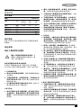
切割能力
宽台钳开口和高枢轴点可切割许多大型工件。参照
切割能力图表确定使用新砂轮可实现的总体最大切
割尺寸。

12
简体中文
警示:某些大型的圆形或不规则形状物体如果
不能使用台钳安全固定,则可能需要额外的固定
方法。
警示:请勿使用本工具切割镁。
最大切割能力
注:
图表显示的是假设砂轮无磨损且处于最佳挡板
位置时的能力。
A x B
ޗऋဳካǖ
90°
೧ރलڡ
45°
೧ރलڡ
A = 4-7/8"
(125ࠒ୶)
A= 4-1/2"
(115ࠒ୶)
A = 4-1/2"
(115ࠒ୶)
A = 3-13/16"
(98ࠒ୶)
4-1/2" x 5-1/8"
(115ࠒ୶ x 130ࠒ୶)
4" x 7-5/8"
(102ࠒ୶ x 188ࠒ୶)
3" x 7-3/8"
(76ࠒ୶ x 229ࠒ୶)
4-1/2" x 4-1/8"
(115ࠒ୶ x 105ࠒ୶)
A = 4-1/2"
(115ࠒ୶)
A = 5-3/8"
(137ࠒ୶)
使用
标准设备
• 355 毫米金属研磨切割轮
• 1 个砂轮扳手
• 1 本使用手册
搬运(图 1)
向下折叠到位,以便搬运型材切割机。将锁定
销(X)推入锁定臂。
安装说明(图 3)
使用两个 M10 螺栓穿过固定的孔,将工具固定于稳
定的位置。
解锁(图 1)
要解锁工具并抬高工具头,请轻轻按下电机臂然后拉
出锁定销(X)。电机臂会沿枢轴向上转动。
火花偏转板调整(图 1)
要尽可能偏转火花以远离周围的人员和材料,请拧
松螺钉(B),调整火花偏转板(C),然后重新拧
紧螺钉。避免电线组件接触偏转板或火花,否则可
能损坏偏转板。
限深器(图 1)
在工厂全新 14 英寸砂轮出厂配备限深器,以防止砂
轮切入支撑面。要增加切割深度,请使用随附的六
角扳手(G)拧松限深器螺栓(M),将螺栓提升到
所需高度,然后顺时针旋转螺帽至到螺帽牢牢固定
在铸件上。使用前拧紧限深器螺栓。
警示:更换新砂轮时,将限深器重新调整到原始位
置以防切入支撑面。
触发开关(图 1)
要启动工具,请按下触发开关(N),接着按下自
锁钮保持机器持续运行。要关闭工具,请再次按下
后松开触发开关。确保双手和材料远离砂轮,直到
砂轮惯性旋转至停止。要防止未经授权使用工具,
请将标准挂锁(另购)安装到触发位置的挂锁孔
(O)。
材料夹紧和支撑
• 最好的夹紧和切割角度是两个脚架稳固支撑在
底座上。
• 垫块比工件稍窄,可增加砂轮利用率(图 2)。
• 长工件必须用垫块支撑以便与底座顶部持
平(图 3)。切割端应可自由下落以避免砂
轮卡住。
台钳操作(图 4)
台钳(F)有快速移动功能。要松开夹紧的台钳,请
将曲柄(H)按逆时针方向旋转一到两次以移除夹紧
压力。抬起台钳拨杆(I)。将曲柄组件向外拉至最
远处。台钳可在不使用曲柄的情况下向前推进到工
件上。放下台钳拨杆(I),然后通过曲柄(F)使
用台钳(H)紧固工件。
挡板操作(图 5、6)
警示:在进行任何调整或者取出或安装附件或配
件之前,请关闭工具的电源并拔下插头。请确保
触发开关处于 OFF(关闭)位置。挡板(E)的
调整方法有两种:更改所需的切割角度以及更改
挡板和台钳之间的间距。
更改所需的切割角度
使用随附的扳手拧松(请勿移除)两颗挡板螺
栓(P)。将所需的角度指示线与底座(Q)上的插
槽线(D)对齐。使用前拧紧两颗挡板螺栓。要实现

13
简体中文
更精确的直角尺切割,请断开电源连接,拧松两颗
挡板螺栓,然后向下推机臂直到砂轮深入底座。紧
靠砂轮放置直角尺,然后根据直角尺调整挡板。
使用前拧紧两颗挡板螺栓。进行斜角切割时,台
钳(F)可能不会夹紧,具体取决于工件的厚度和
斜角角度。进行这些切割时,需要使用其他辅助
工具(如弹簧夹、杆夹或 C 形夹)以将工件固定
到挡板上。
更改挡板和台钳之间的间距
使用随附的扳手拧松并移除两颗挡板螺栓(P)。将
挡板(E)调整到所需位置。在固定位置插入两颗挡
板螺栓。使用前拧紧两颗挡板螺栓。
移除和安装砂轮(图 7、8)
警示:在进行任何调整或者取出或安装附件或配
件之前,请关闭工具的电源并拔下插头。请确保
触发开关处于 OFF(关闭)位置。请勿在砂轮旋
转时进行任何调整。请勿在型材切割机插入电源
时进行任何调整。
1. 推入主轴锁(L)并手动旋转砂轮(J),直到
砂轮锁定杆和内部法兰(R)上的插槽接合以锁
定砂轮。使用 8 毫米六角扳手(G)按逆时针
方向拧松研磨砂轮中心的螺栓(S)。螺栓具有
右旋螺纹。
2. 移除螺栓(S)、垫圈(T)、外部法兰(U)和
旧砂轮(J)。
3. 确保法兰表面干净平整。按照以上相反步骤安
装新研磨砂轮。
4. 请勿过度拧紧螺栓。
警告:更换新研磨砂轮时检查放置型材切割机的
工作表面。机臂完全放下时,砂轮可能会接触工
作表面(底座下)的突出部分或任何突出物体。
警告:确保螺钉始终与护罩连接,并确保更换砂
轮后及使用前,将护罩摆放在正确的位置上,以
保护使用者免受高速旋转砂轮的伤害。
更精确切割的操作提示
• 让砂轮自行切割。用力过度会导致砂轮变光
滑,从而降低切割效率和/或偏转,造成切割不
精确。
• 正确调整挡板角度。
• 确保材料平坦放置在底座上。
• 正确夹紧材料,避免移动和振动。
电机电刷检查和更换(图 9)
警告:关闭电源并拔下工具插头。请确保触发
开关处于 OFF(关闭)位置。应定期检查电刷
是否磨损。要检查电刷,请拧松两颗端盖板螺
钉(V)然后移除端盖板(W)。移除电刷
盖(Y)。电刷(Z)应可在电刷盒中自由
滑动。如果电刷磨损到如图 9 所示的 3 英
寸(8 毫米),则应更换。要重新安装,请将
新电刷推回电刷盒。如果更换现有电刷,请保
持移除时的相同方向。更换电刷盖(请勿拧得
过紧)。更换端盖板和两颗螺钉。然后拧紧。
维护
史丹利电动工具设计精良,可以长时间使用,而且
只需极少的维护。要持续获得令人满意的工作效
果,需要进行合适的工具维护和定期清洁。
• 定期使用软刷或干布清洁工具内的通风槽。
• 定期使用湿布清洁电动机外壳。请勿使用任何
研磨性或基于溶剂的清洁剂。
润滑
本电动工具无需另行润滑
清洁
警告:一旦看到通风口及其周围积聚了
尘屑,请用干燥的空气将灰尘和尘屑从
主机外壳内吹出。执行此过程时,需戴
上经认可的护目装备和防尘面具。
警告:切勿使用溶剂或其他刺激性化学
制品来清洁工具的非金属部件。这些
化学物质可能会削弱这些部位使用的材
料。请用布蘸温和的肥皂水擦拭。切勿
让任何液体渗入工具,切勿让工具的任
何部件浸在液体中。
可选配件
警告:除了史丹利提供的配件之外,其
他配件都未经此产品兼容性测试,如果
将此类配件与本工具一起使用将存在安

14
简体中文
全隐患。为降低伤害风险,本产品仅可
使用史丹利推荐的配件。
警告:仅能使用冲击配件。非冲击型配
件可能会破裂和导致危险情况。使用配
件之前,请检查配件是否处于良好状态
且无裂痕。
请向您的经销商咨询更多关于合适配件的信息。
保护环境
分类回收。本产品不得与普通家庭垃圾
一起处理。
如果您发现您的史丹利产品需要更换或您已经不再
需要使用这些产品,请不要将它们与家庭垃圾一起
处理。请将它们单独分类回收。
分类回收使用过的产品和包装能够让材
料得以再循环和再利用。再生材料的再
利用有助于防止环境污染,并降低对原
材料的需求。
当地法规可能要求由市政废物处理点或向您出售新
产品的零售商提供将家庭废物与电气产品分开收集
的服务。
评价
史丹利的政策是持续改进我们的产品,因此,我们
保留随时更改产品规格的权利,恕不另行通知。
• 标准设备和附件可能会因国家(地区)而异。
• 不同国家(地区)的产品规格也可能会有所
不同。
• 并非所有的国家(地区)都可提供完整的产品系
列。有关各产品系列的供货状况,请联系您当地
的史丹利代理商。
制造商: 史丹利五金工具(上海)有限公司
制造商地址: 中国(上海)自由贸易试验区泰谷路88
号丰谷大楼六层676A室
产地: 上海


-
 1
1
-
 2
2
-
 3
3
-
 4
4
-
 5
5
-
 6
6
-
 7
7
-
 8
8
-
 9
9
-
 10
10
-
 11
11
-
 12
12
-
 13
13
-
 14
14
-
 15
15
-
 16
16


