ページを読み込んでいます...

INSTRUCTION AND
SERVICE MANUAL
ORIGINAL INSTRUCTION
74290 - Model ESAFOR MK II
Hydro-Pneumatic Power Tool
EN
Hydro-Pneumatic Power Tool
JA
油空圧電動ツール
ZSH
液压气动工具

©2021 Stanley Black & Decker inc.
All rights reserved.
The information provided may not be reproduced and/or made public in any way and through any means (electronically or
mechanically) without prior explicit and written permission from STANLEY Engineered Fastening. The information provided
is based on the data known at the moment of the introduction of this product. STANLEY Engineered Fastening pursues a
policy of continuous product improvement and therefore the products may be subject to change. The information provided
is applicable to the product as delivered by STANLEY Engineered Fastening. Therefore, STANLEY Engineered Fastening
cannot be held liable for any damage resulting from deviations from the original specications of the product.
The information available has been composed with the utmost care. However, STANLEY Engineered Fastening will not accept
any liability with respect to any faults in the information nor for the consequences thereof. STANLEY Engineered Fastening
will not accept any liability for damage resulting from activities carried out by third parties. The working names, trade names,
registered trademarks, etc. used by STANLEY Engineered Fastening should not be considered as being free, pursuant to the
legislation with respect to the protection of trademarks.
This instruction manual in ENGLISH is also translated in bellow following languages. On demand the requested instruction
manual shall be provided.
2
ENGLISH ORIGINAL INSTRUCTION

CONTENTS
1. SAFETY DEFINITIONS ................................................................................................................................................... 4
1.1 GENERAL SAFETY RULES .......................................................................................................................................................................... 4
1.2 PROJECTILE HAZARDS .............................................................................................................................................................................. 4
1.3 OPERATING HAZARDS ............................................................................................................................................................................... 5
1.4 REPETITIVE MOTIONS HAZARDS............................................................................................................................................................ 5
1.5 ACCESSORY HAZARDS .............................................................................................................................................................................. 5
1.6 WORKPLACE HAZARDS ............................................................................................................................................................................. 5
1.7 NOISE HAZARDS .......................................................................................................................................................................................... 5
1.8 VIBRATION HAZARDS................................................................................................................................................................................. 5
1.9 ADDITIONAL SAFETY INSTRUCTION FOR PNEUMATIC POWER TOOLS ................................................................................... 6
2. SPECIFICATIONS ............................................................................................................................................................ 7
2.1 INTENT OF USE ............................................................................................................................................................................................. 7
2.2 PLACING TOOL SPECIFICATION .............................................................................................................................................................. 7
2.3 TOOL DIMENSIONS ..................................................................................................................................................................................... 8
3. PUTTING IN SERVICE..................................................................................................................................................... 9
3.1 PRELIMINARY OPERATIONS ..................................................................................................................................................................... 9
3.2 AIR SUPPLY .................................................................................................................................................................................................... 9
3.3 TOOL CONFIGURATION ...........................................................................................................................................................................10
3.4 PRINCIPLE OF OPERATION .....................................................................................................................................................................10
3.5 OPERATING SEQUENCE ........................................................................................................................................................................... 10
4. NOSE ASSEMBLIES ......................................................................................................................................................11
4.1 FITTING INSTRUCTIONS .......................................................................................................................................................................... 11
4.2 SERVICE INSTRUCTIONS ........................................................................................................................................................................11
4.3 74290 NOSE ASSEMBLY COMPONENTS ...........................................................................................................................................11
5. SERVICING THE TOOL..................................................................................................................................................13
5.1 DAILY SERVICING ....................................................................................................................................................................................... 13
5.2 WEEKLY SERVICING ...................................................................................................................................................................................13
5.3 SERVICE KIT ..................................................................................................................................................................................................13
6. MAINTENANCE ............................................................................................................................................................14
6.1 TRIGGER UNIT ............................................................................................................................................................................................ 14
6.2 VERTICAL TRIGGER UNIT (From 43 to 48) .........................................................................................................................................14
6.3 PNEUMATIC PISTON UNIT ......................................................................................................................................................................14
6.4 HYDRAULIC PISTON UNIT .......................................................................................................................................................................14
6.5 PISTON-ROD-PUNCH UNIT ....................................................................................................................................................................14
6.6 MOLYKOTE 55M GREASE ........................................................................................................................................................................15
6.7 PROTECTING THE ENVIRONMENT .......................................................................................................................................................15
7. GENERAL ASSEMBLIES ............................................................................................................................................... 16
7.1 GENERAL ASSEMBLY OF BASE TOOL 74290 .....................................................................................................................................16
7.2 GENERAL ASSEMBLY PARTS LIST 74290 ............................................................................................................................................17
8. PRIMING ......................................................................................................................................................................18
8.1 OIL DETAILS ................................................................................................................................................................................................. 18
8.2 HYSPIN®VG 32 OIL SAFETY DATA .........................................................................................................................................................18
8.3 PRIMING PROCEDURCE ...........................................................................................................................................................................18
8.4 OIL TOP UP ...................................................................................................................................................................................................18
9. FAULT DIAGNOSIS ....................................................................................................................................................... 19
10. EC DECLARATION OF CONFORMITY .......................................................................................................................... 20
11. UK DECLARATION OF CONFORMITY........................................................................................................................ 21
12. PROTECT YOUR INVESTMENT! ...................................................................................................................................22
3
ORIGINAL INSTRUCTION ENGLISH

This instruction manual must be read by any person installing or operating this tool with particular attention to the
following safety rules.
Always wear impact-resistant eye protection during operation of the tool. The grade of protection required should
be assessed for each use.
Use hearing protection in accordance with employer’sinstructions and as required by occupational health and
safety regulations.
Use of the tool can expose the operator’shands to hazards, including crushing, impacts, cuts and abrasions and
heat. Wear suitable gloves to protect hands.
1. SAFETY DEFINITIONS
The denitions below describe the level of severity for each signal word. Please read the manual and pay attention to these
symbols.
DANGER: Indicates an imminently hazardous situation which, if not avoided, will result in death or serious injury.
WARNING: Indicates apotentially hazardous situation which, if not avoided, could result in death or serious injury.
CAUTION: Indicates apotentially hazardous situation which, if not avoided, may result in minor or moderate injury.
CAUTION: Used without the safety alert symbol indicates apotentially hazardous situation which, if not avoided, may
result in property damage.
Improper operation or maintenance of this product could result in serious injury and property damage. Read and
understand all warnings and operating instructions before using this equipment. When using power tools, basic safety
precautions must always be followed to reduce the risk of personal injury.
SAVE ALL WARNINGS AND INSTRUCTIONS FOR FUTURE REFERENCE
1.1 GENERAL SAFETY RULES
• For multiple hazards, read and understand the safety instructions before installing, operating, repairing, maintaining,
changing accessories on, or working near the tool. Failure to do so can result in serious bodily injury.
• Only qualied and trained operators must install, adjust or use the tool.
• DO NOT use outside the design intent specied by Stanley Engineered Fastening.
• Use only parts, fasteners, and accessories recommended by the manufacturer.
• DO NOT modify the tool. Modications can reduce the eectiveness of safety measures and increase the risks to the
operator. Any modication to the tool undertaken by the customer will be the customer’sentire responsibility and void
any applicable warranties.
• Do not discard the safety instructions; give them to the operator.
• Do not use the tool if it has been damaged.
• Prior to use, check for misalignment or binding of moving parts, breakage of parts, and any other condition that
aects the tool’soperation. If damaged, have the tool serviced before using. Remove any adjusting key or wrench
before use.
• Tools shall be inspected periodically to verify that the ratings and markings required by this part of ISO 11148 are legibly
marked on the tool. The employer/user shall contact the manufacturer to obtain replacement marking labels when
necessary.
• The tool must be maintained in asafe working condition at all times and examined at regular intervals for damage
and function by trained personnel. Any dismantling procedure will be undertaken only by trained personnel. Do not
dismantle this tool without prior reference to the maintenance instructions.
1.2 PROJECTILE HAZARDS
• Disconnect the air supply from the tool before performing any maintenance, attempting to adjust, t or remove a nose
assembly or accessories.
• Be aware that failure of the work piece or accessories or even of the inserted tool itself can generate high- velocity
projectiles.
• Always wear impact-resistant eye protection during operation of the tool. The grade of protection required should be
assessed for each use.
• The risks to others should also be assessed at this time.
• Ensure that the work piece is securely xed.
• Warm against the possible forcible ejection of debris from the front of the tool.
• DO NOT operate a tool that is directed towards any person(s).
4
ENGLISH ORIGINAL INSTRUCTION

1.3 OPERATING HAZARDS
• Use of the tool can expose the operator's hands to hazards, including crushing, impacts, cuts and abrasions and heat.
Wear suitable gloves to protect hands.
• Operators and maintenance personnel shall be physically able to handle the bulk, weight and power of the tool.
• Hold the tool correctly; be ready to counteract normal or sudden movements and have both hands available.
• Keep tool handles dry, clean, and free from oil and grease.
• Maintain a balanced body position and secure footing when operating the tool.
• Release the start-and-stop device in the case of an interruption of the air supply.
• Use only lubricants recommended by the manufacturer.
• Contact with hydraulic uid should be avoided. To minimize the possibility of rashes, care should be taken to wash
thoroughly if contact occurs.
• Material Safety Data Sheets for all hydraulic oils and lubricants is available on request from your tool supplier.
• Avoid unsuitable postures, as it is likely for these positions not to allow counteracting of normal or unexpected
movement of the tool.
• If the tool is xed to a suspension device, make sure that the xation is secure.
• Beware of the risk of crushing or pinching if nose equipment is not tted.
• DO NOT operate tool with the nose casing removed.
• Adequate clearance is required for the tool operator’s hands before proceeding.
• When carrying the tool from place to place keep hands away from the trigger to avoid inadvertent activation.
• DO NOT abuse the tool by dropping or using it as a hammer.
1.4 REPETITIVE MOTIONS HAZARDS
• When using the tool, the operator can experience discomfort in the hands, arms, shoulders, neck or other parts of the body.
• While using the tool, the operator should adopt a comfortable posture whilst maintaining a secure footing and
avoiding awkward or o-balance postures. The operator should change posture during extended tasks; this can help
avoid discomfort and fatigue.
• If the operator experiences symptoms such as persistent or recurring discomfort, pain, throbbing, aching, tingling,
numbness, burning sensations or stiness, these warning signs should not be ignored. The operator should tell the
employer and consult a qualied health professional.
1.5 ACCESSORY HAZARDS
• Disconnect the tool from the air supply before tting or removing the nose assembly or accessory.
• Use only sizes and types of accessories and consumables that are recommended by the manufacturer of the tool; do
not use other types or sizes of accessories or consumables.
1.6 WORKPLACE HAZARDS
• Slips, trips and falls are major causes of workplace injury. Be aware of slippery surfaces caused by use of the tool and of
trip hazards caused by the air line or hydraulic hose.
• Proceed with care in unfamiliar surroundings. There can be hidden hazards, such as electricity or other utility lines.
• The tool is not intended for use in potentially explosive atmospheres and is not insulated against contact with electric power.
• Ensure that there are no electrical cables, gas pipes, etc., which can cause a hazard if damaged by use of the tool.
• Dress properly. Do not wear loose clothing or jewellery. Keep your hair, clothing and gloves away from moving parts.
Loose clothes, jewellery or long hair can be caught in moving parts.
1.7 NOISE HAZARDS
• Exposure to high noise levels can cause permanent, disabling hearing loss and other problems, such as tinnitus
(ringing, buzzing, whistling or humming in the ears). Therefore, risk assessment and the implementation of appropriate
controls for these hazards are essential.
• Appropriate controls to reduce the risk may include actions such as damping materials to prevent work pieces from
“ringing”.
• Use hearing protection in accordance with employer's instructions and as required by occupational health and safety
regulations.
• Select, maintain and replace the consumable/inserted tool as recommended in the instruction handbook, to prevent an
unnecessary increase in noise.
1.8 VIBRATION HAZARDS
• Exposure to vibration can cause disabling damage to the nerves and blood supply of the hands and arms.
• Wear warm clothing when working in cold conditions and keep your hands warm and dry.
• If you experience numbness, tingling, pain or whitening of the skin in your ngers or hands, stop using the tool, tell
your employer and consult aphysician.
• Where possible Support the weight of the tool in astand, tensioner or balancer, because alighter grip can then be used
to support the tool.
5
ORIGINAL INSTRUCTION ENGLISH

• Operate and maintain the assembly power tool as recommended in the instruction’s handbook, to prevent an
unnecessary increase in vibration levels.
• Select, maintain and replace the consumable/inserted tool as recommended in the instruction handbook, to prevent an
unnecessary increase in vibration levels.
• Hold the tool with a light but safe grip, taking account of the required hand reaction forces, because the risk from
vibration is generally greater when the grip force is higher.
1.9 ADDITIONAL SAFETY INSTRUCTION FOR PNEUMATIC POWER TOOLS
• The operating supply air must not exceed 7 bar (102 PSI).
• Air under pressure can cause severe injury.
• Never leave operating tool unattended. Disconnect air hose when tool is not in use, before changing accessories or
when making repairs.
• Never direct air at yourself or anyone else.
• Whipping hoses can cause severe injury. Always check for damaged or loose hoses and ttings.
• Prior to use, inspect airlines for damage, all connections must be secure. Do not drop heavy objects on hoses. A sharp
impact may cause internal damage and lead to premature hose failure.
• Cold air shall be directed away from hands.
• Whenever universal twist couplings (claw couplings) are used, lock pins shall be installed and whip check safety cables
shall be used to safeguard against possible hose-to-tool or hose-to-hose connection failure.
• DO NOT lift the placing tool by the hose. Always use the placing tool handle.
• Vent holes must not become blocked or covered.
• Keep dirt and foreign matter out of the hydraulic system of the tool as this will cause the tool to malfunction.
6
ENGLISH ORIGINAL INSTRUCTION

2. SPECIFICATIONS
2.1 INTENT OF USE
The 74290 Tool is designed to convert round holes in to hexagonal holes. The latter are produced by means of a drill. Then
the tool, equipped with punch and reference die, is to be inserted into the hole, where it removes other material in order to
obtain a hexagon hole, ready to receive threaded hexserts.
In this way it is possible to easily and rapidly install threaded inserts which, owing to the hexagon prole, guarantee the on-
rotation of the joint, with evident advantages regarding the production process and the oered performances, compared to
round threaded inserts or other competitor technologies (nuts, welded nuts, etc...).
The use of this tool for threaded inserts enlarges the range of application (up to now it was restricted to the employment of
pre punched sheets) for box type design pieces, low volume series production and in situ applications.
For further details regarding the preparation of the hole in relation to the type of material and the thickness, see page 12.
DO NOT use under wet conditions or in the presence of ammable liquids or gases.
2.2 PLACING TOOL SPECIFICATION
Air Pressure Minimum - Maximum 5-7 bar (75-100 lbf/in)
Free Air Volume Required @ 5 bar/75 lbf/in 8 litres (0.28 ft)
Stroke Maximum 6.5 mm (0.256 in)
Pull Force @ 5.5 bar/ 2400 kgf 23.5 kN (5,290 lbf)
Weight Without nose equipment 2.2 kg (4.85 lb)
Noise values determined according to noise test code ISO 15744 and ISO 3744. 74290
A-weighted sound power level dB(A), LWA Uncertainty noise: kWA = 3.0 dB(A) 89.4 dB(A)
A-weighted emission sound pressure level at the work station
dB(A), LpA
Uncertainty noise: kpA = 3.0 dB(A) 87.4 dB(A)
C-weighted peak emission sound pressure level dB(C), LpC, peak Uncertainty noise: kpC = 3.0 dB(C) 89.8 dB(C)
Vibration values determined according to vibration test code ISO 20643 and ISO 5349 74290
Vibration emission level, ahd:Uncertainty vibration: k = 0.94 m/s 2.36 m/s
Declared vibration emission values in accordance with EN 12096
7
ORIGINAL INSTRUCTION ENGLISH

2.3 TOOL DIMENSIONS
Dimensions shown in bold are millimeters.
8
ENGLISH ORIGINAL INSTRUCTION

3. PUTTING IN SERVICE
IMPORTANT - READ THE SAFETY RULES ON PAGE 4 - 6 CAREFULLY BEFORE PUTTING INTO SERVICE.
• Select relevant size nose equipment and install.
• Connect the placing tool to the air supply. Test pull and return cycles by depressing and releasing the trigger 40.
• Set the tool for desired stroke/pressure.
CAUTION: Correct supply pressure is important for proper function of the installation tool. Personal injury or damage
to equipment may occur without correct pressures. The supply pressure must not exceed that listed in the placing tool
specication.
3.1 PRELIMINARY OPERATIONS
Every day, before using the tool, carry out the operations described in section “LUBRICATION”.
Before connecting the tool to the air supply, blow compressed air through the feed pipe, in order to eliminate any trace of
condensation water or foreign matter.
LUBRICATION: Prior to connecting the air hoses, pour a small quantity of light hydraulic oil into the air admission tting
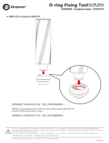
3.2 AIR SUPPLY
All tools are operated with compressed air at an optimum pressure of 5 and 7 Bar. We recommend the use of pressure
regulators and automatic oiling/ltering systems on the main air supply. These should be tted within 3 metres of the tool
(see diagram below) to ensure maximum tool life and minimum tool maintenance.
Air supply hoses should have a minimum working eective pressure rating of 150% of the maximum pressure produced
in the system or 10 bar, whichever is the highest. Air hoses should be oil resistant, have an abrasion resistant exterior and
should be armoured where operating conditions may result in hoses being damaged. All air hoses MUST have a minimum
bore diameter of 6.4 millimetres or 1/4 inch.
We recommend to operate the tool at the minimum pressure necessary to obtain the requested hole, to consume less air
and the maximum tool life is ensured.
Read servicing daily details page 13.
Fig. 2
14
2
3
MAXIMUM
1
1
1
1
1
1
1
1
1
4
4
4
4
4
4
4
4
4
4
4
1
1
4
4
2
2
3
M
A
X
I
M
U
M
STOP COCK
(USEDDURINGMAINTENANCE
OF
FILTER/REGULATOR
OR
LUBRICATIONUNITS)
8
TAKEOFFPOINT
FROMMAINSUPPLY
LUBRICATOR
PRESSURE REGULATOR
AND
FILTER (DRAIN
DAILY
)
MAIN SUPPLY
DRAINPOINT
9
ORIGINAL INSTRUCTION ENGLISH

3.3 TOOL CONFIGURATION
The tool is able to punch hexagon holes, designated to receive metric threaded hexagon inserts type M4, M5, M6, M8, M10.
According to the hole to be realized, the appropriate equipment can be ordered under the relative part number (see Table
on Page 12).
3.4 PRINCIPLE OF OPERATION
Connect the tool provided with the appropriate equipment to the air supply (see table of recommended air pressures in
relation to the material to be punched).
11
3.3.
TOOL CONFIGURATION
The tool is able to punch hexagon holes, designated to receive metric threaded hexagon inserts type M4, M5, M6, M8, M10.
According to the hole to be realized, the appropriate equipment can be ordered under the relative part number (see Table
on Page 15).
3.4.
PRINCIPLE OF OPERATION
Connect the tool provided with the appropriate equipment to the air supply (see table of recommended air pressures in
relation to the material to be punched).
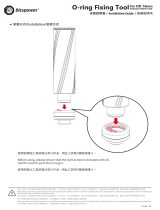
Fig. 1 Fig. 2 Fig. 3 Fig. 4 Fig. 5
Fig.1
Workpiece with round hole.
Fig.2
Insert the punch fixed onto the 74290 Tool into the previously drilled round hole.
Fig.3 Depress the trigger. In this way the rod 24 advances and the punch blades extend on the hole walls,
now the punch is ready to stamp.
Fig.4 In the following the punch removes excess sheet material to create a hexagon hole suitable to place
the hexagon insert.
At the end of this phase the punch retracts from the hole and removes the punching scrap. In general
the scrap is ejected via the punching effect and the return of the punch into the rear position. Scrap
will be expelled without jamming the punch.
Fig.5 The workpiece, with the hexagon hole stamped by the 74290 tool, is now ready to fit a threaded
hexsert.
•
Make sure that no scraps are left on the punch.
•
The tool now is ready for a new operating phase
.
Transforms round holes into hexagonal holes for use of Hexsert® threaded inserts M4 - M10. Thickness range of workpiece
(respective punch equipment has to be ordered seperately):
Aluminium
M4, M10:
0.5 - 2.5 mm
M5 - M8:
0.5 - 4.5 mm
Steel
M4:
0.5 - 1.5 mm
M5 - M10:
0.5 - 3.0 mm
Stainless Steel
M4 - M10:
0.5 - 1.5 mm
Fig.1 Fig.2 Fig.3 Fig.4 Fig.5
Fig.1 Workpiece with round hole.
Fig.2 Insert the punch xed onto the 74290 Tool into the previously drilled round hole.
Fig.3 Depress the trigger. In this way the rod 24 advances and the punch blades extend on the hole walls, now the
punch is ready to stamp.
Fig.4 In the following the punch removes excess sheet material to create a hexagon hole suitable to place the
hexagon insert.
At the end of this phase the punch retracts from the hole and removes the punching scrap. In general the
scrap is ejected via the punching eect and the return of the punch into the rear position. Scrap will be
expelled without jamming the punch.
Fig.5 The workpiece, with the hexagon hole stamped by the 74290 tool, is now ready to t a threaded hexsert.
• Make sure that no scraps are left on the punch.
• The tool now is ready for a new operating phase.
Transforms round holes into hexagonal holes for use of Hexsert® threaded inserts M4 - M10. Thickness range of workpiece
(respective punch equipment has to be ordered seperately):
Aluminium M4, M10: 0.5 - 2.5 mm
M5 - M8: 0.5 - 4.5 mm
Steel M4: 0.5 - 1.5 mm
M5 - M10: 0.5 - 3.0 mm
Stainless Steel M4 - M10: 0.5 - 1.5 mm
3.5 OPERATING SEQUENCE
• Place the punch mounted onto the 74290 Tool
tool inside the round hole.
• Fully depress the trigger of the 74290 tool. The
piston extends the punch and automatically
perforates the sheet material. In doing this,
a punched hexagon hole is produced. A
threaded hexsert can now be inserted by
means of the Stanley Engineered Fastening
tool models 74200 and 74202.
12
3.5.
OPERATING SEQUENCE
•
Place the punch mounted onto the 74290 Tool
tool inside the round hole.
•
Fully depress the trigger of the 74290 tool. The
piston extends the punch and automatically
perforates the sheet material. In doing this, a
punched hexagon hole is produced. A threaded
hexsert can now be inserted by means of the
Stanley Engineered Fastening tool models 74200
and 74202.
Item numbers in
bold
refer to the General Assembly drawing and parts list (pages 18-20).
10
ENGLISH ORIGINAL INSTRUCTION

4. NOSE ASSEMBLIES
It is essential that the correct nose assembly is tted prior to operating the tool. By knowing the details of the fastener to be
placed, you will be able to order a new complete nose assembly using the selection tables on page 12.
4.1 FITTING INSTRUCTIONS
CAUTION: The air supply must be disconnected when tting or removing nose assemblies unless specically instructed
otherwise.
The tting procedure is very simple and described in the following:
Item numbers in bold refer to illustration below on Page 16:
• Disconnect the tool from the air supply.
• Unscrew the outer casing 4 and the coupling sleeve 5, if mounted on the tool.
• Place the punch 1 onto the rod 24, which protrudes from the connection 6 and tighten the parts 6 and 5 using the 17
mm spanner.
• Reattach the outer casing 4.
• Screw the die 2, rst onto the counter lock nut 3 and then onto the casing 4.
• The locking of the die with the counter lock nut, with respect to punch 1, depends on the thickness of the material on
which to realize the hexagon punching. Then t the counter lock nut with a screw nut wrench.
4.2 SERVICE INSTRUCTIONS
Nose assemblies should be serviced at weekly intervals.
• Remove the complete nose assembly using the reverse procedure to the ‘Fitting Instructions’.
• Any worn or damaged part should be replaced by a new part.
• Particularly check wear on Punch.
• Assemble according to tting instructions.
4.3 74290 NOSE ASSEMBLY COMPONENTS
Nose tips vary in shape according to the insert type. Each nose assembly represents a unique assembly of components
which can be ordered individually. Component numbers refer to the illustration on page 16. We recommend some stock
as items will need regular replacement. .
11
ORIGINAL INSTRUCTION ENGLISH

(1)
Adapterkit is required
74290X07555
(included)
(2)
Adapterkit is required
(included)
rev. 01/2011
THIS COMPLETE
EQUIPMENT-
c
ompliteequipment
PunchPunch
Adapter
Matrix Thickness/grip ø Forum/hole indicative
across flats
kitadapter
M4 74290-00004
74290-09571 74290-0910274290-092110,5à2,56,2 à6,3 6.2
no
no
no
no
7429000010kit.
M5 74290-00005
74290-99641 74290-0910274290-092210,5à4,57,2 à7,3 7.2
M6 74290-00006
74290-99741 74290-0910274290-092310,5à4,59,3 à9,4 9.2
M8 74290-00008
74290-99821 74290-0910274290-092410,5à4,511,3à11,5 11.2
M10 74290-00010(2)
74290-09881 74290-0700074290-092510,5 à2,5 13,4à13,613.2
Theequipment described belowiscompatiblewithaluminum, butwedonot recommenduse on this material. They need a thorough cleaning for
everyworkcycle(forminghexagon)
M4 74290-00014(1)
74290-06571 74290-0910274290-062110,5à2,56,2 à6,3 6.274290x07555
M5 74290-00015
74290-06641 74290-0910274290-062210,5à4,57,2 à7,3 7.2
no
M6 74290-00016
74290-06741 74290-0910274290-062310,5à4,59,3 à9,4 9.2
no
M8 74290-00018
74290-06821 74290-0910274290-062410,5à4,511,3à11,5 11.2
no
M10 74290-00020(2)
74290-06881 74290-0700074290-062510,5 à2,5 13,4à13,613.2 7429000010kit.
M4 74290-00014(1)
74290-06571 74290-0910274290-062110,5à1,56,2 à6,3 6.274290x07555
M5 74290-00015
74290-06641 74290-0910274290-062210,5à3,07,2 à7,3 7.2
no
M6 74290-00016
74290-06741 74290-0910274290-062310,5à3,09,3 à9,4 9.2
no
M8 74290-00018
74290-06821 74290-0910274290-062410,5à3,011,3à11,5 11.2
no
M10 74290-00020(2)
74290-06881 74290-0700074290-062510,5 à3,0 13,4à13,613.2 7429000010kit.
M4 74290-00014(1)
74290-06571 74290-0910274290-062110,5à1,56,2 à6,3 6.274290x07555
M5 74290-00015
74290-06641 74290-0910274290-062210,5à1,57,2 à7,3 7.2
no
M6 74290-00016
74290-06741 74290-0910274290-062310,5à1,59,3 à9,4 9.2
no
M8 74290-00018
74290-06821 74290-0910274290-062410,5à1,511,3à11,5 11.2
no
M10 74290-00020(2)
74290-06881 74290-0700074290-062510,5 à1,5 13,4à13,613.2 7429000010kit.
INOX-
stainless
M
M
M
M
ACCIAIO -
steel ALLUMINIO- aluminum
12
ENGLISH ORIGINAL INSTRUCTION

5. SERVICING THE TOOL
Regular servicing should be carried out and a comprehensive inspection performed annually or every 500,000 cycles,
whichever is sooner.
CAUTION: Never use solvents or other harsh chemicals for cleaning the non-metallic parts of the tool. These
chemicals may weaken the materials used in these parts.
CAUTION: Before maintenance, remove any dangerous substances that may have accumulated due to work
processes.
CAUTION: The employer is responsible for ensuring that tool maintenance instructions are given to the
appropriate personnel.
CAUTION: The operator should not be involved in maintenance or repair of the tool unless properly trained.
CAUTION: The tool shall be examined regularly for damage and malfunction.
CAUTION: Read Safety Instructions on page 4 to 6.
5.1 DAILY SERVICING
• Daily, before use or when rst putting the tool into service, pour a few drops of clean, light lubricating oil into the
air inlet of the tool if no lubricator is tted on air supply. If the tool is in continuous use, the air hose should be
disconnected from the main air supply and the tool lubricated every two to three hours.
• Check for air leaks. If damaged, hoses and couplings should be replaced by new items.
• If there is no lter on the pressure regulator, bleed the air line to clear it of accumulated dirt or water before connecting
air hose to tool.
• Check that the nose assembly is correct.
• Check the stroke of the tool is correct.
• Inspect the punch in the nose assembly for wear or damage. If any, renew.
5.2 WEEKLY SERVICING
* Check for oil leaks and air leaks on air supply hose and ttings.
5.3 SERVICE KIT
For all servicing we recommend the use of the service kit (part number 74290-03000) tools below:
SERVICE TOOLS
Description Part Description Part
Spanner 32 mm For part No. 18 Allan key 5 mm For part No. 35
Spanner 20 mm
(part of outt) For part No. 7Allan key 2 mm For part No. 33
Vice with soft jaws For part No. 37 Spanner 12 mm For part No. 75
Flat-nose pliers For part No. 12 Hook device For part No. 83, 28
Spanner 10 mm For part No. 73 Spanner 17 mm For part No. 31
Tubular socket wrench
25 mm For part No. 62 Spanner 22 mm For part No. 4
Allen key 12 mm For part No. 64 Pin Punch For part No. 38
13
ORIGINAL INSTRUCTION ENGLISH

6. MAINTENANCE
Every 500,000 cycles the tool should be completely dismantled and components replaced where worn, damaged or when
recommended. All ‘O’ rings and seals should be replaced with new ones and lubricated with Molykote 55M grease before
assembling.
WARNING: Read Safety Instructions on page 4 to 6.
WARNING: The employer is responsible for ensuring that tool maintenance instructions are given to the
appropriate personnel.
WARNING: The operator should not be involved in maintenance or repair of the tool unless properly trained.
WARNING: The tool shall be examined regularly for damage and malfunction.
The airline must be disconnected before any servicing or dismantling is attempted unless specically instructed otherwise.
It is recommended that any dismantling operation be carried out in clean conditions.
Prior to dismantling the tool it is necessary to remove the nose assembly. For simple removal instructions see the nose
assemblies section, pages 11.
For total tool servicing, we advise that you proceed with dismantling of sub-assemblies in the order shown below.
6.1 TRIGGER UNIT
• Remove the pin 38 and extract the trigger unit 39-40-41-42.
6.2 VERTICAL TRIGGER UNIT FROM 43 TO 48
• To remove this unit it is necessary to disassemble the PNEMATIC PISTON ASSY.
6.3 PNEUMATIC PISTON UNIT
• Unscrew the oil drain screw 35 and bleed the oil.
• Place the tool in an upside-down position in a vice. Take care to use soft jaws so not to damage the body 37.
• Unscrew the 2 nuts 73 (key 10 mm), extract the end plug lock 75 and pay attention to piston 68 which could violently
eject due to spring 65.
• Unscrew the rod guide 62 by means of a 25 mm barrel wrench. In this condition the vertical trigger unit (from 43 to 48)
can be extracted by pressing the rod 43.
• If necessary, separate stem 66 from piston 68, but remember that these two parts for the reassembling must be joint
applying LOCTITE 222 sealing onto the thread of bolt 76.
6.4 HYDRAULIC PISTON UNIT
• Unscrew the outer casing 4, the coupling sleeve 5 and the piston connection 6. Unscrew the 2 screws 33 an d extract
protect ion 21. Unscrew lock screw 26 and move the pipe 27 inside the cylinder 19.
• Detach piston 7 from the piston-rod-punch unit. For this purpose insert the 20 mm wrench behind piston 7 and the 32
mm wrench in head 18, then unscrew. Unscrew the screws 17 and extract limit stop 16 and spring 15, then pull out the
hydraulic piston.
• To replace the lip seal 83 remove the Seeger circlip ring 12.
6.5 PISTON-ROD-PUNCH UNIT
• Place the pneumatic cylinder at the respective circumference sparing into the vise.
• Draw o the spring 25.
• Unscrew the head 18 with a 32 mm wrench.
• In this way the parts 24, 23, 22 can be extracted.
CAUTION: Priming is ALWAYS necessary after the tool has been dismantled and prior to operating.
Item numbers in bold refer to the General Assembly drawing and parts list (pages 16-17).
14
ENGLISH ORIGINAL INSTRUCTION

6.6 MOLYKOTE 55M GREASE
Grease can be ordered as a single item, the part number is shown in the service kit page 13.
FIRST AID
SKIN: Wipe o and wash with soap and water.
INGESTION: No adverse eects are normally expected. Treat symptomatically.
EYES: Irritant but not harmful. Irrigate with water and seek medical attention.
ENNVIRONMENT
Scrape up for incinerating or disposal on approved site.
FIRE
FLASH POINT: 101°C
Not classied as ammable.
Suitable extinguishing media: Carbon dioxide, foam, dry powder or ne water spray.
HANDLING
Plastic or rubber gloves should be worn.
STORAGE
Away from heat and oxidizing agent
6.7 PROTECTING THE ENVIRONMENT
Assure conformity with applicable disposal regulations. Dispose all waste products at an approved waste facility or site so as
not to expose personnel and the environment to hazards.
15
ORIGINAL INSTRUCTION ENGLISH

7. GENERAL ASSEMBLIES
7.1 GENERAL ASSEMBLY OF BASE TOOL 74290
16
ENGLISH ORIGINAL INSTRUCTION

7.2 GENERAL ASSEMBLY PARTS LIST 74290
Parts List for MKII Tool - 74290-03000
ITEM PART N° DESCRIPTION QTY ITEM PART N° DESCRIPTION QTY ITEM PART N° DESCRIPTION QTY
1 see manual punch 1 31 74290-03012 end plug 1 61 07003-00134 O-ring 1
2 see manual die 1 32 74290-03013 cylinder jacket 1 62 74200-12015 rod guide 1
3 see manual counter lock nut 1 33 74290-03014 fastening screw M3 2 63 74200-12014 washer 1
4 07555-00315 outer casing 1 34 74200-12060 O-ring 2 64 74200-12013 nut 1
5 74290-09102 coupling sleeve 1 35 07005-01274 oil drain screw 1 65 07555-00205 spring 1
6 07555-00314 piston connection 1 36 74290-03015 screw washer 1 66 74290-03018 stem 1
7 74290-03001 piston 1 37 74290-03016 body 1 67 74290-03019 tie rods 2
8 07003-00028 O-ring 1 38 74200-12026 pin 1 68 74290-03020 pneumatic piston 1
9 74200-12099 washer 1 39 74200-12024 push wedge 1 69 74290-03021 lip seal 1
10 74200-12049 bleed washer 1 40 74200-12025 trigger 1 70 74290-03022 O-ring 2
11 07001-00329 bleed screw 1 41 74200-12023 roll 1 71 74290-03023 O-ring 1
12 07004-00033 Seeger circlip ring 2 42 74200-12022 pin 1 72 74290-03024 washer 2
13 74290-03002 suspension ring 1 43 74200-12020 trigger rod 1 73 74290-03025 nuts 2
14 74200-12053 lip seal 1 44 07003-00315 O-ring 1 74 74290-03026 rubber base 1
15 07555-00317 spring 1 45 74200-12019 guide 1 75 74290-03027 end plug lock 1
16 74290-03003 limit stop 1 46 74200-12018 lip seal 1 76 74290-03028 bolt 1
17 74290-03004 screw M4 4 47 74290-03017 valve plug 1 77 74200-12103 plug 1
18 07555-00320 rod cylinder head 1 48 07003-00027 O-ring 1 78 07003-00029 O-ring 4
19 74290-03005 rod cylinder 1 49 74200-12302 deector 1 79 74290-03029 air inlet pipe 1
20 07555-00324 seal rod cylinder 1 50 74200-12301 set screw 1 80 74200-12700 Air Connector 1
21 74290-03006 protection 1 51 74200-12033 washer 1/8 1 81 74290-03033 Anti Rotation Plug 1
22 07555-00323 pusher piston 1 52 07003-00046 O-ring 1 82 74290-03032 Stroke Stop 1
23 07265-03206 nut 1 53 07003-00026 O-ring 1 83 07265-02004 Lip Seal 1
24 74290-03007 pusher 1 54 74200-12104 spring 1 84 07007-01526 CE & UKCA Label 1
25 07555-00321 spring 1 55 07003-00086 O-ring 1 85 73200-02022 Safety Label 1
26 74290-03008 pipe lock screw M3 1 56 07003-00040 O-ring 1 86 07007-02221 74290 Label 1
27 74290-03009 Delrin pipe 1 57 74200-12028 valve piston 1
28 74290-03010 retarder 1 58 74200-12027 nut 1
29 74290-03011 O-ring 2 59 74200-12034 silencer 1
30 74200-12029 O-ring 1 60 07003-00100 O-ring 1
17
ORIGINAL INSTRUCTION ENGLISH

8. PRIMING
Priming is ALWAYS necessary after the tool has been dismantled and prior to operating. It may also be necessary to restore the full
stroke after considerable use, when the stroke may be reduced and fasteners are not fully placed by one operation of the trigger.
8.1 OIL DETAILS
The recommended oil for priming is Hyspin® VG32 available in 0.5l (part number 07992-00002) or one gallon containers
(part number 07992-00006). Please see safety data below.
8.2 HYSPIN®VG 32 OIL SAFETY DATA
FIRST AID
SKIN:
Wash thoroughly with soap and water as soon as possible. Casual contact requires no immediate attention. Short term
contact requires no immediate attention.
INGESTION:
Seek medical attention immediately. DO NOT induce vomiting.
EYES:
Irrigate immediately with water for several minutes. Although NOT a primary irritant, minor irritation may occur following
contact.
FIRE
Flash point 232°C. Not classied as ammable.
Suitable extinguishing media: CO2, dry powder, foam or water fog. DO NOT use water jets.
ENVIRONMENT
WASTE DISPOSAL: Through authorized contractor to a licensed site.May be incinerated. Used product may be sent for
reclamation. SPILLAGE: Prevent entry into drains, sewers and water courses. Soak up with absorbent material.
HANDLING
Wear eye protection,impervious gloves (e.g. of PVC) and a plastic apron. Use in well ventilated area.
STORAGE
No special precautions.
8.3 PRIMING PROCEDURCE
CAUTION: Ensure that the oil is perfectly clean and free from air bubbles.
CAUTION: The tool must remain on its side throughout the priming sequence.
CAUTION: All operations should be carried out on a clean bench, with clean hands, in a clean area.
CAUTION: Care MUST be taken, at all times, to ensure that no foreign matter enters the tool, or serious damage
may result.
8.4 OIL TOP UP
• Place the tool in horizontal position.
• Unscrew the oil drain screw 35 using a 5 mm Allan key.
• Pour the recommended oil into the hole leading to the chamber in which the piston rod runs.
• Make sure that the screw washer 36 is in the correct position.
• Screw again with moderation the oil drain screw 35 using the Allan key.
• Now bleed the tool. This operation is necessary to ensure that all air bubbles are eliminated.
• Make sure the drain screw 11 is tightly closed, unscrew the same ONLY BY ONE TURN using an Allan key, then connect
the tool to the air supply and depress the trigger.
• Wait until oil appears around the drain screw 11, then retighten. Clean the excess oil.
• Release the trigger.
• Open the oil drain screw 35 using an Allan key.
• Top up with priming oil to reset level. Replace the screw washer 36 and the oil drain screw 35 in position and close tightly.
• Prior to operating the tool it is necessary to t the appropriate tip equipment and to adjust the tool stroke.
18
ENGLISH ORIGINAL INSTRUCTION

9. FAULT DIAGNOSIS
SYMPTOM POSSIBLE CAUSE REMEDY
Air Leakage from Pipe Connection 27 O-Ring Defective REPLACE
Punching Rod does not properly
extend the punch inside the hole Tail jaws switched o. Switch on tail jaws
Punching Rod does not advance /
return Debris material between Rod and
Punch
If necessary disassemble the
equipment (Head) including the
punch, then clean
Hexagon seats too small Punch worn Rod diameter diminished REPLACE visually check that the
diameter is not smaller than 3,95mm
Tool is not able to produce the seat
Punch worn stroke too small
REPALCE
Visually check the Oil level by opening
the oil drain screw 35. If necessary Top
Up with prescribed Oil.
Pneumatic return spring 65 broken or
excessively stressed REPLACE If possible operate with lower Air
Pressure
Oil Leakage FRONT: Lip Seal 83 worn or scored or
hydraulic piston rod scored.
REPLACE the worn or damaged parts
to restore the tightness.
BACK: Washer 14 worn or scored or the
nish of internal cylinder is scored. Top-Up Oil.
LOWER PART: Washer 63 is worn or
pneumatic piston rod scored.
Air Leakage AT THE TRIGGER: Check O-Rings 44 REPLACE If Worn
AT AIR ESCAPE: Check wear condition
of LIP seal 69.
AT AIR PIPE CONNECTION 27: Check
the correct installation of pipe and
wear condition of O-Rings 34.
19
ORIGINAL INSTRUCTION ENGLISH

10. EC DECLARATION OF CONFORMITY
We, Stanley Engineered Fastening, Stanley House, Works Road, Letchworth Garden City, Hertfordshire,
SG6 1JY UNITED KINGDOM, declare under our sole responsibility that the product:
Description: 74290 Hydro-Pneumatic Tool
Model: 74290
to which this declaration relates is in conformity with the following harmonized standards:
ISO 12100:2010 EN ISO 3744:2010
EN ISO 11202:2010 EN ISO 11148-1:2011
EN ISO 4413:2010 BS EN 28662-1:1993
EN ISO 4414:2010 EN ISO 20643:2008+A1:2012
EN ISO 28927-5:2009+A1:2015 ES100118-rev 17:2017
Technical documentation is compiled in accordance with Annex VII, in accordance with the following Directive: 2006/42/EC
The Machinery Directive (Statutory Instruments 2008 No 1597 - The Supply of Machinery (Safety) Regulations refers).
The undersigned makes this declaration on behalf of STANLEY Engineered Fastening
A. K. Seewraj
Director of Engineering, UK
Avdel UK Limited, Stanley House, Works Road, Letchworth Garden City, Hertfordshire,
SG6 1JY UNITED KINGDOM
Place of issue: Letchworth Garden City, UK
Date of issue: 01-01-2021
The undersigned is responsible for compilation of the technical le for products sold in the European Union and makes this
declaration on behalf of Stanley Engineered Fastening.
Matthias Appel
Team Leader Technical Documentation
Stanley Engineered Fastening, Tucker GmbH, Max-Eyth-Str.1,
35394 Gießen, Germany
This machinery is in conformity with
Machinery Directive 2006/42/EC
20
ENGLISH ORIGINAL INSTRUCTION
/