Bosch GTS 10 J Original Instructions Manual
- カテゴリー
- パワーツール
- タイプ
- Original Instructions Manual
このマニュアルも適しています

Robert Bosch GmbH
Power Tools Division
70745 Leinfelden-Echterdingen
Germany
www.bosch-pt.com
1 619 929 J34 (2011.07) PS / 93 ASIA
GTS 10 J Professional
en Original instructions
cn 正本使用说明书
tw 正本使用說明書
ko
th หนังสือคูมือการใชงานฉบับตนแบบ
id Petunjuk-Petunjuk untuk
Penggunaan Orisinal
vi BΩng hõëng dÿn nguy›n bΩn
OBJ_BUCH-1473-001.book Page 1 Monday, July 18, 2011 10:33 AM

2 |
1 619 929 J34 | (18.7.11) Bosch Power Tools
English . . . . . . . . . . . . . . . . . . . . . . . . . . . . . . . . . . . . . . . . . . Page 15
中文 . . . . . . . . . . . . . . . . . . . . . . . . . . . . . . . . . . . . . . . . . . . . 页 26
中文 . . . . . . . . . . . . . . . . . . . . . . . . . . . . . . . . . . . . . . . . . . . . 頁 35
45
ภาษาไทย . . . . . . . . . . . . . . . . . . . . . . . . . . . . . . . . . . . . . . . . หนา 55
Bahasa Indonesia . . . . . . . . . . . . . . . . . . . . . . . . . . . . . . Halaman 67
Tiøng Vi·t . . . . . . . . . . . . . . . . . . . . . . . . . . . . . Trang 79
OBJ_BUCH-1473-001.book Page 2 Monday, July 18, 2011 10:33 AM

| 3
Bosch Power Tools 1 619 929 J34 | (18.7.11)
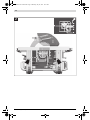
GTS 10 J
Professional
1 2 3 4 5
4
14
15
16
4
11
12
6
7 8 9
1318 1117
10
19202122
72
71
OBJ_BUCH-1473-001.book Page 3 Monday, July 18, 2011 10:33 AM

1 619 929 J34 | (18.7.11) Bosch Power Tools
4 |
10 23 24 25 26 27 28 29 2
31 11 31 3034 11 3233
OBJ_BUCH-1473-001.book Page 4 Monday, July 18, 2011 10:33 AM

| 5
Bosch Power Tools 1 619 929 J34 | (18.7.11)
24 35
A
OBJ_BUCH-1473-001.book Page 5 Monday, July 18, 2011 10:33 AM

1 619 929 J34 | (18.7.11) Bosch Power Tools
6 |
E2E1
D
C
B2B1
26 6
10
9
5
103839
36
40
29
37
39
5
3
3
41
42
6
7
25
14
OBJ_BUCH-1473-001.book Page 6 Monday, July 18, 2011 10:33 AM

| 7
Bosch Power Tools 1 619 929 J34 | (18.7.11)
I
HG
F
GTA 60 W
Professional
GTA 600
Professional
32
33
11
11
43
32
OBJ_BUCH-1473-001.book Page 7 Monday, July 18, 2011 10:33 AM

1 619 929 J34 | (18.7.11) Bosch Power Tools
8 |
LK
J4J3
J2J1
24
156
50
3
27 46
max. 5 mm
49
51
52
45
20 19
47
48
44
OBJ_BUCH-1473-001.book Page 8 Monday, July 18, 2011 10:33 AM

| 9
Bosch Power Tools 1 619 929 J34 | (18.7.11)
P
O
N
26
M
38 9
27
53
9
13
36
28
25
13
1
17
1
2
OBJ_BUCH-1473-001.book Page 9 Monday, July 18, 2011 10:33 AM

1 619 929 J34 | (18.7.11) Bosch Power Tools
10 |
S
R
Q2Q1
22
22
54
9 38 16
5
3
9
4229
51
OBJ_BUCH-1473-001.book Page 10 Monday, July 18, 2011 10:33 AM

| 11
Bosch Power Tools 1 619 929 J34 | (18.7.11)
U
T2T1
59
5855 1920
56 49 57
60 60
61 61
OBJ_BUCH-1473-001.book Page 11 Monday, July 18, 2011 10:33 AM

1 619 929 J34 | (18.7.11) Bosch Power Tools
12 |
Y2Y1
XW
V
28
33
64
65
63
39
62
1
24
53
66
6
34
67
OBJ_BUCH-1473-001.book Page 12 Monday, July 18, 2011 10:33 AM

| 13
Bosch Power Tools 1 619 929 J34 | (18.7.11)
Y6
Y5
Y4Y3
31 3138
69
14
69
65
69
70
3
68 16 15
9
OBJ_BUCH-1473-001.book Page 13 Monday, July 18, 2011 10:33 AM

1 619 929 J34 | (18.7.11) Bosch Power Tools
14 |
Z
OBJ_BUCH-1473-001.book Page 14 Monday, July 18, 2011 10:33 AM

English | 15
Bosch Power Tools 1 619 929 J34 | (18.7.11)
English
Safety Notes
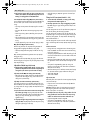
General Power Tool Safety Warnings
When using electric tools basic safety
precautions should always be followed
to reduce the risk of fire, electric shock and personal injury in-
cluding the following.
Read all these instructions before attempting to operate
this product and save these instructions.
The term “power tool” in the warnings refers to your mains-
operated (corded) power tool or battery-operated (cordless)
power tool.
Work area safety
f Keep work area clean and well lit. Cluttered or dark areas
invite accidents.
f Do not operate power tools in explosive atmospheres,
such as in the presence of flammable liquids, gases or
dust. Power tools create sparks which may ignite the dust
or fumes.
f Keep children and bystanders away while operating a
power tool. Distractions can cause you to lose control.
Electrical safety
f Power tool plugs must match the outlet. Never modify
the plug in any way. Do not use any adapter plugs with
earthed (grounded) power tools. Unmodified plugs and
matching outlets will reduce risk of electric shock.
f Avoid body contact with earthed or grounded surfaces,
such as pipes, radiators, ranges and refrigerators.
There is an increased risk of electric shock if your body is
earthed or grounded.
f Do not expose power tools to rain or wet conditions.
Water entering a power tool will increase the risk of electric
shock.
f Do not abuse the cord. Never use the cord for carrying,
pulling or unplugging the power tool. Keep cord away
from heat, oil, sharp edges and moving parts. Damaged
or entangled cords increase the risk of electric shock.
f When operating a power tool outdoors, use an exten-
sion cord suitable for outdoor use. Use of a cord suitable
for outdoor use reduces the risk of electric shock.
f If operating a power tool in a damp location is unavoid-
able, use a residual current device (RCD) protected
supply. Use of an RCD reduces the risk of electric shock.
Personal safety
f Stay alert, watch what you are doing and use common
sense when operating a power tool. Do not use a power
tool while you are tired or under the influence of drugs,
alcohol or medication. A moment of inattention while op-
erating power tools may result in serious personal injury.
f Use personal protective equipment. Always wear eye
protection. Protective equipment such as dust mask,
non-skid safety shoes, hard hat, or hearing protection
used for appropriate conditions will reduce personal inju-
ries.
f Prevent unintentional starting. Ensure the switch is in
the off-position before connecting to power source
and/or battery pack, picking up or carrying the tool.
Carrying power tools with your finger on the switch or en-
ergising power tools that have the switch on invites acci-
dents.
f Remove any adjusting key or wrench before turning
the power tool on. A wrench or a key left attached to a ro-
tating part of the power tool may result in personal injury.
f Do not overreach. Keep proper footing and balance at
all times. This enables better control of the power tool in
unexpected situations.
f Dress properly. Do not wear loose clothing or jewel-
lery. Keep your hair, clothing and gloves away from
moving parts. Loose clothes, jewellery or long hair can be
caught in moving parts.
f If devices are provided for the connection of dust ex-
traction and collection facilities, ensure these are con-
nected and properly used. Use of dust collection can re-
duce dust-related hazards.
Power tool use and care
f
Do not force the power tool. Use the correct power tool
for your application. The correct power tool will do the
job better and safer at the rate for which it was designed.
f Do not use the power tool if the switch does not turn it
on and off. Any power tool that cannot be controlled with
the switch is dangerous and must be repaired.
f Disconnect the plug from the power source and/or the
battery pack from the power tool before making any
adjustments, changing accessories, or storing power
tools. Such preventive safety measures reduce the risk of
starting the power tool accidentally.
f Store idle power tools out of the reach of children and
do not allow persons unfamiliar with the power tool or
these instructions to operate the power tool. Power
tools are dangerous in the hands of untrained users.
f Maintain power tools. Check for misalignment or bind-
ing of moving parts, breakage of parts and any other
condition that may affect the power tool’s operation. If
damaged, have the power tool repaired before use.
Many accidents are caused by poorly maintained power
tools.
f Keep cutting tools sharp and clean. Properly maintained
cutting tools with sharp cutting edges are less likely to bind
and are easier to control.
f Use the power tool, accessories and tool bits etc. in ac-
cordance with these instructions, taking into account
the working conditions and the work to be performed.
Use of the power tool for operations different from those
intended could result in a hazardous situation.
Service
f Have your power tool serviced by a qualified repair per-
son using only identical replacement parts. This will en-
sure that the safety of the power tool is maintained.
W
ARN
I
N
G
OBJ_BUCH-1473-001.book Page 15 Monday, July 18, 2011 10:33 AM

16 | English
1 619 929 J34 | (18.7.11) Bosch Power Tools
Safety Warnings for Table Saws
f Never stand on the power tool. Serious injuries can occur
when the power tool tips over or when inadvertently com-
ing into contact with the saw blade.
f Take care that the blade guard operates properly and
can move freely. Always adjust the blade guard in such a
manner that it faces loosely against the workpiece when
sawing. Never clamp the blade guard when it is open.
f Keep hands away from the cutting area while the ma-
chine is running. Danger of injury when coming in contact
with the saw blade.
f Never reach behind the saw blade in order to hold the
workpiece, remove saw dust/wood chips or for any oth-
er reason. The clearance of your hand to the rotating saw
blade is too small.
f Guide the workpiece against the saw blade only when
the machine is switched on. Otherwise there is damage
of kickback, when the saw blade becomes wedged in the
workpiece.
f Keep handles dry, clean, and free from oil and grease.
Greasy, oily handles are slippery causing loss of control.
f Operate the power tool only when the work area to the
workpiece is clear of any adjusting tools, wood chips,
etc. Small pieces of wood or other objects that come in
contact with the rotating saw blade can strike the operator
with high speed.
f Only saw one workpiece at a time. Workpieces placed on
top or aside of each other can cause the saw blade to jam
or the workpieces to move against each other while saw-
ing.
f Always use the parallel guide or the angle guide. This
improves the cutting accuracy and reduces the possibility
of saw blade binding.
f Use the machine for grooving or rebating only with an
appropriately suitable protective device (e. g. a tunnel
blade guard).
f Do not use the machine for cutting slots (stopped
grooves).
f Use the machine only for cutting the materials listed
under Intended Use. Otherwise, the machine can be sub-
ject to overload.
f If the saw blade should become jammed, switch the ma-
chine off and hold the workpiece until the saw blade
comes to a complete stop. To prevent kickback, the
workpiece may not be moved until after the machine
has come to a complete stop. Correct the cause for the
jamming of the saw blade before restarting the machine.
f Do not use dull, cracked, bent or damaged saw blades.
Unsharpened or improperly set saw blades produce nar-
row kerf causing excessive friction, blade binding and kick-
back.
f Always use saw blades with correct size and shape (dia-
mond versus round) of arbor holes. Saw blades that do
not match the mounting hardware of the saw will run ec-
centrically, causing loss of control.
f Do not use high speed steel (HSS) saw blades. Such saw
blades can easily break.
f Do not touch the saw blade after working before it has
cooled. The saw blade becomes very hot while working.
f Never operate the machine without the insert plate.
Replace a defective insert plate. Without flawless insert
plates, injuries are possible from the saw blade.
f Check the cable regularly and have a damaged cable re-
paired only through an authorised customer service
agent for Bosch power tools. Replace damaged exten-
sion cables. This will ensure that the safety of the power
tool is maintained.
f Store the machine in a safe manner when not being
used. The storage location must be dry and lockable.
This prevents the machine from storage damage, and from
being operated by untrained persons.
f Never leave the machine before it has come to a com-
plete stop. Cutting tools that are still running can cause in-
juries.
f Never use the machine with a damaged cable. Do not
touch the damaged cable and pull the mains plug when
the cable is damaged while working. Damaged cables in-
crease the risk of an electric shock.
Products sold in GB only: Your product is fitted with a
BS 1363/A approved electric plug with internal fuse (ASTA
approved to BS 1362).
If the plug is not suitable for your socket outlets, it should be
cut off and an appropriate plug fitted in its place by an author-
ised customer service agent. The replacement plug should
have the same fuse rating as the original plug.
The severed plug must be disposed of to avoid a possible
shock hazard and should never be inserted into a mains sock-
et elsewhere.
Products sold in AUS and NZ only: Use a residual current de-
vice (RCD) with a rated residual current of 30 mA or less.
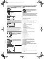
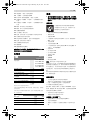
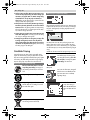
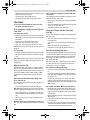
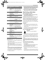
Symbols
The following symbols can be important for the operation of
your power tool. Please memorise the symbols and their
meanings. The correct interpretation of the symbols helps
you operate the power tool better and more secure.
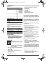
Symbols and their meaning
Keep hands away from the cutting area
while the machine is running. Danger of
injury when coming in contact with the saw
blade.
Wear a dust respirator.
Wear ear protectors. Exposure to noise
can cause hearing loss.
OBJ_BUCH-1473-001.book Page 16 Monday, July 18, 2011 10:33 AM

English | 17
Bosch Power Tools 1 619 929 J34 | (18.7.11)
Product Description and Specifica-
tions
Read all safety warnings and all instruc-
tions. Failure to follow the warnings and in-
structions may result in electric shock, fire
and/or serious injury.
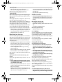
Intended Use
The power tool is intended as a stationary machine for making
straight lengthways and crossways cuts in hard and soft-
wood, as well as in particle and fibre board. In this, mitre an-
gles from –60° to +60° as well as bevel angles from –2° to
47° are possible.
When using appropriate saw blades, sawing aluminium pro-
files and plastic is also possible.
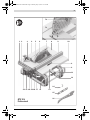
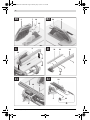
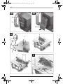
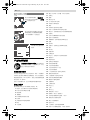
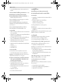
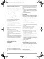
Product Features
The numbering of the components shown refers to the repre-
sentation of the power tool on the graphic pages.
1 Scale for clearance of the saw blade to the parallel
guide 9
2 Guide groove for parallel guide 9
3 Angle stop
4 Recessed handles
5 Guide groove for angle stop
6 Blade guard
7 Clamping screw for mounting blade guard 6
8 Saw table
9 Parallel guide
10 V-guide groove on saw table for parallel guide
11 Mounting holes
12 Carrying handle
13 Saw-Table extension
14 Allen key (5 mm)
15 Ring spanner (23 mm)
16 Push stick
17 Tensioning lever for saw-table extension
18 Fastening bracket for saw stand GTA 600
19 Locking lever for adjustment of bevel angles
20 Handwheel
21 Crank for lowering and raising the saw blade
22 Safety flap of On/Off switch
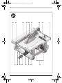
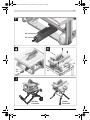
23 Adjustment screw for tightening tension of guide 37
24 Insert plate
25 Riving knife
26 Clamping lever for locking the height of blade guard 6
27 Saw blade
28 Lens
29 Profile rail
30 Cable holder
31 Retaining bracket for storage of the auxiliary parallel
guide
Wear safety goggles.
Do not dispose of power tools into house-
hold waste!
Observe the dimensions of the saw blade. The hole diameter
must match the tool spindle without play. Do not use reduc-
ers or adapters.
When changing the saw blade, pay attention that the kerf
width is not less than 2.3 mm and the blade thickness not
greater than 2.3 mm. Otherwise, there is danger that the riv-
ing knife (2.3 mm) becomes wedged in the workpiece.
The maximal possible workpiece height is 79 mm.
Left side
Indicates the rotation direction of the
handwheel for lowering (transport
position) and raising (working posi-
tion) the saw blade.
Right side
Indicates the position of the locking le-
ver for locking the saw blade and for
adjusting the bevel angle (saw blade
tiltable).
If required, lubricate the
power tool at the indicat-
ed locations.
Symbols and their meaning
OBJ_BUCH-1473-001.book Page 17 Monday, July 18, 2011 10:33 AM

18 | English
1 619 929 J34 | (18.7.11) Bosch Power Tools
32 Sawdust ejector
33 Extraction adapter
34 Fixture for storage of the blade guard
35 Insert-plate notches
36 Clamping handle of the parallel guide
37 V-guide of parallel guide
38 Auxiliary parallel guide
39 “Auxiliary parallel guide” fastening kit
40 Guide rail of the angle stop
41 “Profile rail ”fastening kit
42 Knurled nut for profile rail
43 Fastening screw for sawdust ejector
44 Clamping nut
45 Spindle lock lever
46 Clamping flange
47 Tool spindle
48 Mounting flange
49 Indicator for bevel angle
50 Scale for bevel angle
51 Locking knob for various mitre angles
52 Angle indicator on the angle guide
53 Saw-table clearance indicator
54 ON button
55 Phillips screw for adjustment of stop 56
56 Stop for 0° bevel angle
57 Screw for bevel angle indicator
58 Phillips screw for adjustment of stop 59
59 Stop for 45° bevel angle
60 Front Allen screws (5 mm) for parallelism adjustment of
the saw blade
61 Rear Allen screws (5 mm) for parallelism adjustment of
the saw blade
62 Screw for saw-table clearance indicator
63 Screw for parallel guide clearance indicator
64 Adjusting screws for insert plate
65 Allen key (2 mm)
66 Holder for storage of “auxilliary parallel guide fastening
kit”
67 Retaining clamp for storage of the extraction adapter
68 Fastening nut for the ring spanner and for attaching the
push stick
69 Holder for storage of the Allen key
70 Retaining clamp for storage of the angle stop
71 Side protector
72 Locking screw of side protector
Accessories shown or described are not part of the standard deliv-
ery scope of the product. A complete overview of accessories can
be found in our accessories program.
Technical Data
Assembly
f Avoid unintentional starting of the machine. During as-
sembly and for all work on the machine, the power plug
must not be connected to the mains supply.
Delivery Scope
Please also observe the representation of the
delivery scope at the beginning of the operat-
ing instructions.
Before starting the operation of the machine
for the first time, check if all parts listed be-
low have been supplied:
– Table saw with mounted saw blade 27 and riving knife 25
–Angle stop 3
– Profile rail 29
– Fastening kit “profile rail” 41 (guide plate, knurled nut,
screw, washer)
– Parallel guide 9
– Auxiliary parallel guide 38
– “Auxiliary parallel guide” fastening kit 39 (3 fastening
screws, 3 washers, 3 wing nuts)
– Blade guard 6
– Allen key 14
– Allen key 65
– Ring spanner 15
–Push stick 16
– Insert plate 24
– Extraction adapter 33
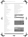
Table saw GTS 10 J
Professional
Article number
3 601 M30 540
3 601 M30 580
3 601 M30 5B0
3 601 M30 5K0
3 601 M30 5L0
Rated power input
W 1800
No-load speed
min
-1
3650
Reduced starting current
z
Weight according to
EPTA-Procedure 01/2003
kg 26
Protection class
/II
Dimensions (incl. removable product features)
Width x depth x height
mm 578 x 706 x 330
Maximum workpiece dimensions, see page 22.
The values given are valid for a nominal voltage [U] of 230 V. For differ-
ent voltages and models for specific countries, these values can vary.
Please observe the article number on the type plate of your machine.
The trade names of the individual machines may vary.
Dimension of suitable saw blades
Saw blade diameter
mm 254
Blade body thickness
mm 1.7–1.9
Tooth thickness/setting, min.
mm 2.6
Mounting hole diameter
mm 25.4
OBJ_BUCH-1473-001.book Page 18 Monday, July 18, 2011 10:33 AM

English | 19
Bosch Power Tools 1 619 929 J34 | (18.7.11)
Note: Check the power tool for possible damage.
Before further use of the machine, check that all protective
devices are fully functional. Any lightly damaged parts must
be carefully checked to ensure flawless operation of the tool.
All parts must be properly mounted and all conditions fulfilled
that ensure faultless operation.
Damaged protective devices and parts must be immediately
replaced by an authorised service centre.
Mounting Individual Components
– Carefully remove all parts included in the delivery from
their packaging.
Remove all packaging material from the machine and the
accessories provided.
– Take care that the packaging material under the motor
block es removed.
The following product features are fastened directly to the
housing:
Push stick 16, ring spanner 15, allen key 14 and 65, parallel
guide 9, angle guide 3, extraction adapter 33, auxiliary paral-
lel guide 38 with fastening kit 39, blade guard 6.
– Carefully remove these product features from their stor-
age locations.
Also see figures Y1–Y6.
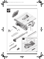
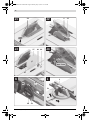
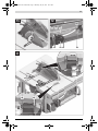
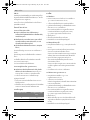
Mounting the Insert Plate (see figure A)
– Hook insert plate 24 into the rear insert-plate notches 35
of the tool basin.
– Guide the insert plate down.
– Press on the insert plate until it engages at the front in the
tool basin.
The front side of the insert plate 24 must be flush with or
somewhat lower than the saw table; the rear side must be
flush with or somewhat above the saw table. (also see “Ad-
justing the Level of the Insert Plate”, page 23)
Mounting the Blade Guard (see figure B1)
– Turn crank 21 clockwise to the stop, so that the saw blade
27 is in the highest possible position above the saw table.
– Pull the riving knife 25 upward to the stop.
– Insert the blade guard 6 into the recess in riving knife 25.
– Tighten clamping screw 7 with Allen key 14.
Adjusting the Blade-guard Height (see figure B2)
Adjust the blade guard according to the workpiece height.
When sawing, the blade guard must always face lightly against
the workpiece.
– For this, loosen clamping lever 26, adjust the appropriate
height of blade guard 6 and then tighten the clamping lever
again.
Mounting the Parallel Guide (see figure C)
The parallel guide 9 can be positioned either left or right from
the saw blade.
– Loosen clamping handle 36 of parallel guide 9.
This releases V-guide 37.
– Firstly, mount the parallel guide via the V-guide in guide
groove 10 of the saw table. Now, position the parallel
guide into the front guide groove 2
of the saw table.
The parallel guide can now be moved to any position.
– To lock the parallel guide, press the clamping handle 36
down.
Mounting the Auxiliary Parallel Guide (see figure D)
When sawing narrow workpieces and bevel angles, the
auxiliary parallel guide 38 must be mounted to parallel guide
9.
The auxiliary parallel guide can be mounted left or right from
parallel guide 9, as required.
For assembly, use the “auxiliary parallel guide” fastening kit
39. (3 fastening screws, 3 washers, 3 wing nuts)
– Insert the fastening screws through the lateral holes in the
parallel guide 9.
The heads of the screws serve as a guide for the auxiliary
parallel guide.
– Move the auxiliary parallel guide 38 over the heads of the
fastening screws.
– Mount the washers to the fastening screws and tighten
them with the wing nuts .
Mounting the Angle Stop (see figures E1 – E2)
– Insert the guide rail 40 of the angle stop 3 into one of the
guide grooves 5 of the saw table intended for this purpose.
For improved placement of long workpieces, the angle stop
can be extended with profile rail 29.
– If required, mount the profile rail to the angle stop with fas-
tening kit 41.
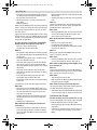
Dust/Chip Extraction
Dusts from materials such as lead-containing coatings, some
wood types, minerals and metal can be harmful to one’s
health. Touching or breathing-in the dusts can cause allergic
reactions and/or lead to respiratory infections of the user or
bystanders.
Certain dusts, such as oak or beech dust, are considered as
carcinogenic, especially in connection with wood-treatment
additives (chromate, wood preservative). Materials contain-
ing asbestos may only be worked by specialists.
– Always use dust extraction.
– Provide for good ventilation of the working place.
– It is recommended to wear a P2 filter-class respirator.
Observe the relevant regulations in your country for the mate-
rials to be worked.
The dust/chip extraction can be blocked by dust, chips or
workpiece fragments.
– Switch the machine off and pull the mains plug from the
socket outlet.
– Wait until the saw blade has come to a complete stop.
– Determine the cause of the blockage and correct it.
f Prevent dust accumulation at the workplace. Dusts can
easily ignite.
f To avoid the danger of fire when sawing aluminium,
empty the sawdust ejector and do not work with
dust/chip extraction.
OBJ_BUCH-1473-001.book Page 19 Monday, July 18, 2011 10:33 AM

20 | English
1 619 929 J34 | (18.7.11) Bosch Power Tools
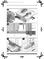
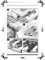
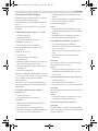
Emptying the Sawdust Ejector (see figure F)
The sawdust ejector 32 can be emptied for removal of work-
piece fragments and large chips.
– Switch the machine off and pull the mains plug from the
socket outlet.
– Wait until the saw blade has come to a complete stop.
– Loosen fastening screw 43 with Allen key 14.
– Pull out sawdust ejector 32 and remove workpiece frag-
ments and chips.
– Mount the sawdust ejector to the power tool again.
External Dust Extraction (see figure G)
To connect a vacuum cleaner to the sawdust ejector 32, use
the supplied extraction adapter 33.
– Firmly attach the extraction adapter 33 and the vacuum
hose.
The vacuum cleaner must be suitable for the material being
worked.
When vacuuming dry dust that is especially detrimental to
health or carcinogenic, use a special vacuum cleaner.
Stationary or Flexible Mounting
f To ensure safe handling, the machine must be mounted
on a level and stable surface (e. g., workbench) prior to
using.
Mounting to a Working Surface (see figure H)
– Fasten the power tool with suitable screw fasteners to the
working surface. The mounting holes 11 serve for this pur-
pose.
Mounting to a Bosch Saw Stand (see figure I)
With the height-adjustable legs, Bosch saw stands (e. g.
GTA 60 W, GTA 600) provide firm support for the power tool
on any surface.
f Read all safety warnings and instructions included with
the worktable. Failure of observing safety warnings and
instructions can lead to electrical shock, fire and/or cause
serious injuries.
f Assemble the worktable properly before mounting the
power tool. Perfect assembly is important in order to pre-
vent the risk of collapsing.
– Mount the power tool in transport position on the saw
stand.
Changing the Saw Blade (see figures J1– J4)
f Before any work on the machine itself, pull the mains
plug.
f When mounting the saw blade, wear protective gloves.
Danger of injury when touching the saw blade.
Use only saw blades whose maximum permitted speed is
higher than the no-load speed of the power tool.
Use only saw blades that correspond with the characteristic
data given in these operation instructions and that are tested
and marked in accordance with EN 847-1.
Use only saw blades recommended by the tool manufacturer,
and suitable for sawing the materials to be cut.
Removing the Saw Blade
– Using a screwdriver, raise the insert plate 24 at the front
and remove it from the tool basin.
– Turn crank 21 clockwise to the stop, so that the saw blade
27 is in the highest possible position above the saw table.
– Loosen clamping lever 26, pull blade guard 6 upward to
the stop and then tighten the clamping lever again.
– Turn the clamping nut 44 with the ring spanner 15
(23 mm) and at the same time, pull the spindle lock lever
45 until it engages.
– Keep the spindle lock lever pulled and unscrew the clamp-
ing nut turning in anticlockwise direction.
– Remove the clamping flange 46.
– Remove the saw blade 27.
Mounting the Saw Blade
If required, clean all parts to be mounted prior to assembly.
– Place the new saw blade onto the supporting flange 48 of
the tool spindle 47.
Note: Do not use saw blades that are too small. The clearance
between saw blade and riving knife must not exceed 5 mm
(max.).
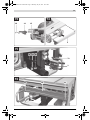
f When mounting the saw blade, pay attention that the
cutting direction of the teeth (arrow direction on the
saw blade) corresponds with the direction of the arrow
on the blade guard!
– Mount the clamping flange 46 and the clamping nut 44.
– Turn the clamping nut 44 with the ring spanner 15
(23 mm) and at the same time, pull the spindle lock lever
45 until it engages.
– Tighten the clamping nut in clockwise direction. (Tighten-
ing torque approx. 15–23 Nm)
– Reinsert the insert plate 24.
– Tilt blade guard 6 down again.
Operation
f Before any work on the machine itself, pull the mains
plug.
Transport and Working Position of the Saw Blade
Transport Position
– Turn crank 21 in anticlockwise direction until the teeth of
the saw blade 27 are positioned below the saw table 8.
– Slide the table extension 13 completely inward.
Press tensioning lever 17 downward.
The saw-table extension is now locked.
For additional information on transport, see page 23.
Working Position
– Turn the crank 21 clockwise, until the teeth of the saw
blade 27 are positioned above the workpiece.
Note: Take care that the blade guard is properly positioned.
When sawing, it must always face against the workpiece.
OBJ_BUCH-1473-001.book Page 20 Monday, July 18, 2011 10:33 AM
ページが読み込まれています...
ページが読み込まれています...
ページが読み込まれています...
ページが読み込まれています...
ページが読み込まれています...
ページが読み込まれています...
ページが読み込まれています...
ページが読み込まれています...
ページが読み込まれています...
ページが読み込まれています...
ページが読み込まれています...
ページが読み込まれています...
ページが読み込まれています...
ページが読み込まれています...
ページが読み込まれています...
ページが読み込まれています...
ページが読み込まれています...
ページが読み込まれています...
ページが読み込まれています...
ページが読み込まれています...
ページが読み込まれています...
ページが読み込まれています...
ページが読み込まれています...
ページが読み込まれています...
ページが読み込まれています...
ページが読み込まれています...
ページが読み込まれています...
ページが読み込まれています...
ページが読み込まれています...
ページが読み込まれています...
ページが読み込まれています...
ページが読み込まれています...
ページが読み込まれています...
ページが読み込まれています...
ページが読み込まれています...
ページが読み込まれています...
ページが読み込まれています...
ページが読み込まれています...
ページが読み込まれています...
ページが読み込まれています...
ページが読み込まれています...
ページが読み込まれています...
ページが読み込まれています...
ページが読み込まれています...
ページが読み込まれています...
ページが読み込まれています...
ページが読み込まれています...
ページが読み込まれています...
ページが読み込まれています...
ページが読み込まれています...
ページが読み込まれています...
ページが読み込まれています...
ページが読み込まれています...
ページが読み込まれています...
ページが読み込まれています...
ページが読み込まれています...
ページが読み込まれています...
ページが読み込まれています...
ページが読み込まれています...
ページが読み込まれています...
ページが読み込まれています...
ページが読み込まれています...
ページが読み込まれています...
ページが読み込まれています...
ページが読み込まれています...
ページが読み込まれています...
ページが読み込まれています...
ページが読み込まれています...
ページが読み込まれています...
ページが読み込まれています...
ページが読み込まれています...
ページが読み込まれています...
-
 1
1
-
 2
2
-
 3
3
-
 4
4
-
 5
5
-
 6
6
-
 7
7
-
 8
8
-
 9
9
-
 10
10
-
 11
11
-
 12
12
-
 13
13
-
 14
14
-
 15
15
-
 16
16
-
 17
17
-
 18
18
-
 19
19
-
 20
20
-
 21
21
-
 22
22
-
 23
23
-
 24
24
-
 25
25
-
 26
26
-
 27
27
-
 28
28
-
 29
29
-
 30
30
-
 31
31
-
 32
32
-
 33
33
-
 34
34
-
 35
35
-
 36
36
-
 37
37
-
 38
38
-
 39
39
-
 40
40
-
 41
41
-
 42
42
-
 43
43
-
 44
44
-
 45
45
-
 46
46
-
 47
47
-
 48
48
-
 49
49
-
 50
50
-
 51
51
-
 52
52
-
 53
53
-
 54
54
-
 55
55
-
 56
56
-
 57
57
-
 58
58
-
 59
59
-
 60
60
-
 61
61
-
 62
62
-
 63
63
-
 64
64
-
 65
65
-
 66
66
-
 67
67
-
 68
68
-
 69
69
-
 70
70
-
 71
71
-
 72
72
-
 73
73
-
 74
74
-
 75
75
-
 76
76
-
 77
77
-
 78
78
-
 79
79
-
 80
80
-
 81
81
-
 82
82
-
 83
83
-
 84
84
-
 85
85
-
 86
86
-
 87
87
-
 88
88
-
 89
89
-
 90
90
-
 91
91
-
 92
92


Bosch GTS 10 J Original Instructions Manual
- カテゴリー
- パワーツール
- タイプ
- Original Instructions Manual
- このマニュアルも適しています