
DOC273.98.90146
PHOSPHAX sigma High Range
Supplement to DOC023.98.90397
User manual
03/2017, Edition 3


3
Table of contents
English..................................................................................................................................................... 5
Deutsch.................................................................................................................................................. 15
英语......................................................................................................................................................... 25

4
Table of contents

English 5
Specifications
English
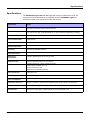
Specifications
The PHOSPHAX sigma HR sets itself apart with a larger measurement range. All
necessary technical modifications as compared with the PHOSPHAX sigma are
described in detail in this supplement to the user manual.
Specification
Details
Measurement method
Reduction method, derived from DIN 38405 D11,
photometric evaluation using IR LED photometer
Measurement ranges
0.01–0.50 to 10.0 mg/L P total phosphate in 0.1 mg/L increments
0.01–0.50 to 10.0 mg/L P orthophosphate in 0.1 mg/L increments (depending on design)
Measurement interval
15–240 minutes at 5 minute steps, "remote" and "off"
Time of measurement
0–600 minutes
Sample requirement
Approximately 100 mL/h
Ambient temperature
+ 5 °C to + 40 °C (41 °F to 104 °F)
Calibration
Automatic at selectable intervals
Inspection interval
3 months
Maintenance
requirements
Typically, approximately 1/2 an hour per week
Reagent storage
3 months (standard solution 6 to 12 months)
Outputs
2 current outputs: 0/4...20 mA, maximum 500
Ω
2 limit contacts: isolated, 24 V 1 A
Service interface: RS 232
Interface: bus-compatible (optional)
Type of protection
In line with IP 54
Power supply
230 V AC voltage ± 10%/50–60 Hz
Power consumption
Approximately 310 VA (incl. refrigerator)
Dimensions: W x H x D
550 mm x 1190 mm x 390 mm (incl. refrigerating set) (21.65 x 46.85 x 15.35 inches)
Weight
Approximately 43 kg (without reagents)
Miscellaneous
Cleaning unit, data logger, graphical display showing hydrograph curve

6 English
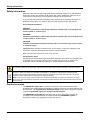
Safety information
Safety information
Read the instructions carefully and in full before unpacking, setting up or operating this
instrument. Please pay attention to all danger and caution statements. Failure to do so
could result in serious injury to the operator or damage to the instrument.
To ensure that the protection provided by this instrument is not impaired, do not use or
install this instrument in any manner other than that specified in this user manual.
Use of hazard information
DANGER
Indicates a potentially or imminently hazardous situation that, if not avoided, will
result in death or serious injury.
WARNING
Indicates a potentially or imminently hazardous situation that, if not avoided, could
result in death or serious injury.
CAUTION
Indicates a potentially hazardous situation that, if not avoided, may result in minor
or moderate injury.
Important note: Indicates a situation that, if not avoided, could lead to damage to the
instrument. Important information that requires special emphasis.
Note: Information that supplements points in the main text.
Precautionary labels
Pay attention to all the labels, tags and stickers attached to the instrument. Personal injury
or damage to the instrument could occur if not
observed. A symbol, if noted on the
instrument, will be included with a danger or caution statement in the manual.
Product overview
The PHOSPHAX sigma HR is a process photometer used to determine the total
phosphate and orthophosphate (depending on design) present in secondary effluent and
surface water. This supplement to DOC023.53.03113 is only valid in conjunction with the
complete PHOSPHAX sigma user manual DOC023.53.03113.
The PHOSPHAX sigma HR sets itself apart with a larger measurement range. All
necessary technical modifications as compared with the PHOSPHAX sigma are
described in detail in this supplement to the user manual.
This symbol, if noted on the instrument, references the operation and/or safety information in the user's manual.
Electrical equipment marked with this symbol may not be disposed of in European public disposal systems after
August 12, 2005, but instead must be collected separately. In accordance with European local and national
regulations (EU Directive 2002/96/EC), European electrical equipment users must now return old or end-of life
equipment to the manufacturer for disposal at no charge to the user.
Note: For return for recycling, please contact the instrument manufacturer or supplier for instructions on how to
return old or end-of life electrical equipment, manufacturer-supplied electrical accessories and all auxiliary items for
proper disposal.

English 7
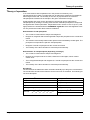
Theory of operation
Theory of operation
In an acidic solution with molybdate ions in the presence of antimony ions,
orthophosphate ions create a complex that can be reduced to phosphorus molybdenum
blue using ascorbic acid. The intensity of the color is proportional to the volume of
orthophosphate contained in the sample in the given measurement range.
Polyphosphate and some organic phosphorus compounds can be hydrolyzed to
orthophosphate by heating in a strong acidic solution. Resistant phosphorus compounds
are digested with sodium persulfate. Temperatures well in excess of 100 °C (212 °F) and
high pressures are obtained with the PHOSPHAX sigma HR. Such short digestion times
can only be achieved under these extreme conditions.
Determination of total phosphate
• The cuvette is rinsed with the sample and reagent B.
• Reagent A, reagent B and the homogenized sample are pumped into the cuvette and
mixed.
• The solution is then briefly heated under pressure and immediately cooled again. The
phosphorus compounds are split into orthophosphate.
• Reagents C and D are pumped into the cuvette and mixed.
• The intensity of the blue coloration is measured photometrically.
Determination of orthophosphate (depending on design)
• The cuvette is rinsed with the sample and reagent B.
• Reagent A is pumped into the cuvette, heated and cooled again, which creates
sulfuric acid.
• The homogenized sample and reagents B, C and D are pumped into the cuvette and
mixed.
• The intensity of the blue coloration is measured photometrically.
Disruptions
The ions listed in the table below were checked individually up to the given concentrations.
The overall effect as well as the influence of other ions was not recorded. The following do
not cause disruption:
40 g/L SO
4
2
–
200 mg/L J
–
20 g/L Cl
–
100 gm/L SiO
2
8 g/L K
+
, Na
+
80 gm/L Hg
2+
2 g/L Ca
2+
50 gm/L Sn
2+
800 mg/L Mg
2+
40 mg/L Pb
2+
400 mg/L
CO
3
2
–
, NO
2
–
, Fe
3+
, Fe
2+
, Cd
2+
, NH
4
,
AL
3+
, Zn
2+
, Cu
2+
, Co
2+
, Ni
2+
, Mn
2+
20 mg/L Ag
+
, Cr
3+
2 mg/L Cr
6+

8 English
Installation
Installation
Please pay attention to all information related to wall mounting, installation of infeed and
discharge points as well as all information about electrical connections in the PHOSPHAX
sigma user manual DOC023.53.03113.
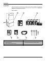
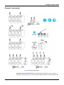
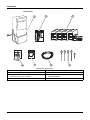
Items supplied
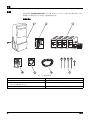
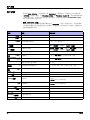
Figure 1 Items supplied
1 PHOSPHAX Σ sigma including refrigerator 5 Wear parts set (new instrument)
2 Small parts set 6 LZP 573 6 m discharge hose
3 LCW 893 reagent set
LCW 824 standard solution (2 mg/L)
7 Screw caps with hose hole for reagent canister
4 Maintenance schedule, certificate of compliance

English 9
Installation
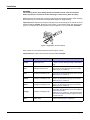
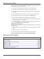
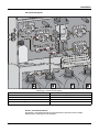
Plan of hose system
Metering and valve hoses
All metering and valve hoses for a piece of equipment must be identifiable by means of
set
colors.
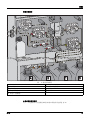
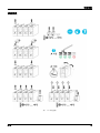
Figure 2 Plan of hose system
1 Discharge hose 6 Reagent A metering hose
2 Valve hose 7 Reagent B metering hose
3 Sample metering hose 8 Sample infeed
4 Reagent C metering hose 9 Discharge
5 Reagent D metering hose

10 English
Installation
WARNING
The metering hoses must always be disconnected from the relevant canisters
before any work is carried out to the metering or valve hoses. (Risk of reflux)
Metering hoses are hoses that connect to the sample and reagent pumps. Each metering
hose must only be connected to the applicable sample or reagent pump.
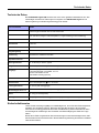
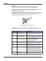
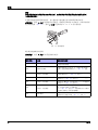
Important note: Replace the sample metering hose, the discharge hose and the hose for
reagent B after 3 months. Brush the pump rollers on the sample pump with silicon paste
(
Figure 3). Replace the metering hoses for the reagents A, B, C and D after 6 months.
Valve hoses are connections between the hose pinch valves.
Important note: Valve hoses must be replaced after 6 months.
Figure 3 Application of silicon paste
Color code Designation Course in instrument
Purple Discharge hose
Runs from the cuvette intake (Figure 2, position
1, page 9) via the discharge pump to the exterior
wall
Red Sample metering hose
Runs from hose pinch valves Q1 and Q2 (T piece
valve hose) via the sample pump to the cuvette
intake (Figure 2, position 3)
Red Reagent B metering hose
Runs from reagent B canister via the hose pinch
valve Q3 and via the sample pump to the cuvette
intake (Figure 2, position 7)
Yellow Reagent C metering hose
Runs from reagent C canister via the reagent
pump C, D (dual-channel pump) to the cuvette
intake (Figure 2, position 4)
Black Reagent D metering hose
Runs from reagent D canister via the reagent
pump C, D (dual-channel pump) to the cuvette
intake (Figure 2, position 5)
Orange Reagent A metering hose
Runs from reagent A canister via the hose pinch
valve QA in the refrigerator and via the reagent A
pump to the cuvette
intake (Figure 2, position 6). The small air hose at
the bottom end (also marked orange) is inserted
into the front slot.
Red Valve hose
Feed hose for sample, reagent B, standard
solution and air (Figure 2, position 2).

English 11
Installation
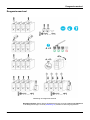
Hose pinch valves
There are four hose pinch valves. Three hose pinch valves in the upper part of the
instrument (Q1, Q2 and Q3) connect the sample, reagent B, air and standard solution to
the sample pump.
The fourth hose pinch valve in the refrigerator (QA) pipes reagent A and air to the reagent
A pump.
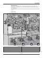
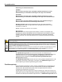
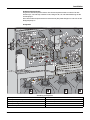
Analysis part
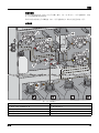
Figure 4 Analysis part
1 Discharge pump 6 Hose pinch valve Q1
2 Sample/reagent/standard B pumps 7 Hose pinch valve Q3
3 Reagent A pump 8 Hose pinch valve QA
4 Reagent C/D pumps 9 Digestion cuvette
5 Hose pinch valve Q2

12 English
User interface
User interface
The menu items MEAS. INTERVAL and MEAS. DELAY have been added to the +SETTINGS
menu in the user interface. All other menus and user operations have remained
unchanged in the move from Phosphax sigma to Phosphax sigma HR and will not be
explained in this supplement. Further information can be found in the PHOSPHAX sigma
user manual DOC023.53.03113.
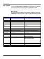
Menu + SETTINGS
All instrument parameters for adjustment to the appropriate conditions are defined in the
+SETTINGS menu. While the instrument is in this menu, further measurements are carried
out and the current output is updated. If no buttons are pressed for over ten minutes, the
instrument returns automatically to the measurement operation display.
Designation Function Available settings
CONTRAST Readability of display -90 to +90
LANGUAGE Selection of menu language DE, GB, FR, NL
STANDARD Concentration of standard solution in use 1.95–2.05 in 0.1 increments
+SPECIAL P Submenu for total phosphorus settings FACTOR, CUR. RANGE, CURRENT, FAULT
+SPECIAL OP Submenu for orthophosphate settings FACTOR, CUR. RANGE, CURRENT, FAULT
P/OP
Number of measurement cycles per
parameter
0–10 each
RELAY-MIN Lower limit contact 0.00 to CUR. OUT P setting
RELAY-MAX Upper limit contact 0.00 to CUR. OUT P setting
SIGMATAX Sample feed via SIGMATAX Yes, no
MEAS. INTERVAL Time between two measurements 15 to 240 minutes in 5 minute steps, remote, off
MEAS. DELAY
Wait time before a measurement,
to rinse pipes etc.
0 ... 600 minutes
DATE Date setting MM:DD:YY
TIME Time setting HH:MM, am, pm
CLEAN Automatic cleaning
Off, 6 h, 12 h, 1–7 days, start time always on the hour
->LAST Last clean displayed
CALIBRATION Automatic calibration
Off, 1–7 days, start time always on the hour
->LAST Last calibration displayed
VERSION Program version
PASSWORD Password protection on activation 4 characters using digits 1–4
SW-LOAD EPROM type Yes, no
SERVICE
STATION
Place and contact
LIGHTING Display illumination On, 20 minutes (after pressing button), time 5°°-17°°


14 English
Replacement parts & reagents
prepared reagent solutions can be stored for 3 months, after which time the canisters
and remaining contents must be discarded.
1. Pour additional component A into the reagent A canister using the funnel.
2. Pour additional component D into the reagent D canister using the funnel.
3. Close reagent canisters A and D using new caps and shake each one thoroughly for
one minute.
4. Stick one label displaying the contents on each of the reagent canisters A and D.
5. Press a menu button for three seconds and select the
+SERVICE menu.
6. Open the refrigerator and remove the reagent hoses from the canisters.
7. Remove the old reagent canisters from the refrigerator, unscrew the caps and replace
them with the caps from the new canisters.
8. Place the new canisters in the refrigerator, connect the hoses, close the refrigerator,
then select
PREPUMPING and then CALIBRATION.
Replacement of standard solution
The standard solution is ready to use. Replace the standard solution every 6–12 months,
depending on use.
1. Remove the old bottle of standard solution, unscrew cap and replace with cap of new
bottle.
2. Insert new bottle, screw cap onto intake hose.
3. The exact concentration of the standard solution is printed on the bottle.
Enter the standard concentration in the
+SETTINGS> STANDARD MENU.
Replacement parts & reagents
Description Order no.
Reagents A, B, C and D and additional components LCW893
Annual wear parts set LZV809
Reagent A, 5 L canister BCF689
Additional component A, 250 mL wide-mouth bottle BCZ822
Reagent B, 5 L canister BCF1161
Reagent C, 5 L canister BCF691
Reagent D, 5 L canister BCF692
Additional component D, 100 mL wide-mouth bottle BCZ824
Standard solution, 500 mL square bottle LCW824

Deutsch 15
Technische Daten
Deutsch
Technische Daten
Das PHOSPHAX sigma HR zeichnet sich durch einen größeren Messbereich aus. Alle
notwendigen technischen Änderungen im Vergleich zum PHOSPHAX sigma sind in
dieser Ergänzung zur Bedienungsanleitung genau erklärt.
Sicherheitshinweise
Lesen Sie die Anleitung sorgfältig und vollständig durch, bevor Sie das Gerät auspacken,
aufstellen und in Betrieb nehmen. Beachten Sie bitte alle Hinweise, die mit Gefahr,
Vorsicht bzw. Achtung gekennzeichnet sind. Nichtbeachtung dieser Informationen kann
schwerwiegende Verletzungen der Anwender oder Beschädigung am Gerät zur Folge
haben.
Damit die im Gerät vorgesehenen Schutzvorrichtungen nicht beeinträchtigt werden, darf
das Gerät auf keinen Fall anders als in dieser Bedienungsanleitung beschrieben installiert
oder benutzt werden.
Technische Daten
Details
Messverfahren
Reduktionsmethode, abgeleitet aus DIN 38405 D11,
Auswertung photometrisch über IR-LED-Photometer
Messbereiche
0,01–0,50 bis 10,0 mg/L P Gesamtphosphat in 0,1 mg/L-Schritten
0,01–0,50 bis 10,0 mg/L P ortho-Phosphat in 0,1 mg/L-Schritten (je nach Ausführung)
Messintervall
15–240 min in 5 min.-Schritten, „remote“ und „aus“
Messwertzeit
0–600 min.
Probebedarf
ca. 100 mL/h
Umgebungstemp.
+ 5°C bis + 40°C (41°F bis 104°F)
Kalibrierung
automatisch in wählbaren Intervallen
Inspektionsintervall
3 Monate
Wartungsaufwand
ca. 1/2 Stunde pro Woche, typisch
Reagenzienvorrat
3 Monate (Standardlösung 6 bis 12 Monate)
Ausgänge
2 Stromausgänge: 0/4...20 mA, max. 500
Ω
2 Grenzwertkontakte: potenzialfrei, 24 V 1A
Service-Schnittstelle: RS 232
Schnittstelle: busfähig (optional)
Schutzart
gemäß IP 54
Netzanschluss
230 V Wechselspannung ± 10% / 50–60 Hz
Leistungsaufnahme
ca. 310 VA (inkl. Kühlaggregat)
Abmessungen: B x H x T
550 mm x 1.190 mm x 390 mm (inkl. Kühlaggregat) (21.65 x 46.85 x15.35 inch)
Masse
ca. 43 kg (ohne Reagenzien)
Sonstiges
Reinigungsautomatik, Datenlogger, Grafik-Display mit Gangliniendarstellung

16 Deutsch
Produktüberblick
Bedeutung von Gefahrenhinweisen
GEFAHR
Weist auf eine potenzielle oder unmittelbare Gefahrensituation hin, deren
Nichtbeachtung zu ernsthaften Verletzungen oder sogar zum Tod führt.
ACHTUNG
Weist auf eine potenzielle oder unmittelbare Gefahrensituation hin, deren
Nichtbeachtung zu ernsthaften Verletzungen oder sogar zum Tod führen kann.
VORSICHT
Weist auf eine potenzielle Gefahrensituation hin, deren Nichtbeachtung zu
kleineren oder mittelschweren Verletzungen führen kann.
Wichtiger Hinweis: Weist auf eine Situation hin, die, wenn nicht vermieden,
Beschädigung am Gerät zur Folge haben kann. Wichtige Informationen, auf die
besonders zu achten ist.
Hinweis: Zusätzliche Informationen zum Haupttext.
Warnetiketten
Beachten Sie alle am Gerät angebrachten Etiketten, Schilder und Aufkleber. Bei
Nichtbeachtung dieser Warnetiketten können Verletzungen oder Schäden am Gerät
auftreten. Wenn dieses Symbol am Gerät angebracht ist, sollten die zugehörigen
Gefahrenhinweise oder Vorsichtsmaßnahmen in der Bedienungsanleitung beachtet
werden.
Produktüberblick
Das PHOSPHAX sigma HR ist ein Prozess-Photometer zur Bestimmung von
Gesamtphosphat und Ortho-Phosphat (je nach Ausführung) im Kläranlagenablauf und
Oberflächenwasser. Die vorliegende Ergänzung zu DOC023.72.03113 ist nur in
Verbindung mit der ausführlichen Bedienungsanleitung PHOSPHAX sigma
DOC023.72.03113 gültig.
Das PHOSPHAX sigma HR zeichnet sich durch einen größeren Messbereich aus. Alle
notwendigen technischen Änderungen im Vergleich zum PHOSPHAX sigma sind in
dieser Ergänzung zur Bedienungsanleitung genau erklärt.
Funktionsprinzip
Ortho-Phosphat-Ionen bilden in saurer Lösung mit Molybdat-Ionen in Gegenwart von
Antimon-Ionen einen Komplex, der durch Ascorbinsäure zu Phosphormolybdänblau
reduziert wird. Die Farbintensitat ist dem Ortho-Phosphat-Gehalt der Probe im
angegebenen Messbereich proportional.
Polyphosphate und einige organische Phosphorverbindungen werden durch Kochen in
stark saurer Lösung zu Ortho-Phosphat hydrolysiert. Beständige Phosphorverbindungen
werden durch Natriumperoxodisulfat aufgeschlossen. Im PHOSPHAX sigma HR wird bei
Wenn dieses Symbol am Gerät angebracht ist, verweist es auf Bedienungs- und/oder Sicherheitshinweise in der
Bedienungsanleitung.
Elektrogeräte, die mit diesem Symbol gekennzeichnet sind, dürfen nach dem 12. August 2005 nicht im normalen
öffentlichen Abfallsystem entsorgt werden, sondern müssen gesondert gesammelt werden. Nach den Maßgaben
der EU-Richtlinie 2002/96/EG müssen Elektro- und Elektronik-Altgeräte kostenlos von den Nutzern zur Entsorgung
an den Hersteller zurückgegeben werden können.
Hinweis: Zur Rücknahme zwecks Recycling wenden Sie sich bitte an den Hersteller oder Lieferanten des Geräts,
um Informationen zur Rückgabe von Elektro- und Elektronik-Altgeräten, zu den vom Hersteller geliefertem
Elektrozubehör und zu allen Zusatzteilen zur vorschriftsmäßigen Entsorgung zu erhalten.

Deutsch 17
Installation
Temperaturen weit über 100 °C unter Druck gearbeitet. Nur unter diesen extremen
Bedingungen sind so kurze Aufschlusszeiten möglich.
Gesamtphosphat-Bestimmung
• Die Küvette wird mit Probe und Reagenz B gespült.
• Reagenz A, Reagenz B und homogenisierte Probe werden in die Küvette gepumpt
und gemischt.
• Die Lösung wird unter Druck kurz aufgeheizt und sofort wieder abgekühlt. Die
Phosphorverbindungen werden zu Ortho-Phosphat aufgespalten.
• Reagenz C und D werden in die Küvette gepumpt und gemischt.
• Die Intensität der Blaufärbung wird photometrisch gemessen.
Ortho-Phosphat-Bestimmung (je nach Ausführung)
• Die Küvette wird mit Probe und Reagenz B gespült.
• Reagenz A wird in die Küvette gepumpt, erhitzt und wieder abgekühlt, hierbei entsteht
Schwefelsäure.
• Homogenisierte Probe, Reagenz B, C und D werden in die Küvette gepumpt und
gemischt.
• Die Intensität der Blaufärbung wird photometrisch gemessen.
Störungen
Die in der Tabelle aufgeführten Ionen wurden bis zu den angegebenen Konzentrationen
einzeln überprüft. Die summarische Wirkung sowie der Einfluss weiterer Ionen wurde
nicht ermittelt. Es stören nicht:
Installation
Beachten Sie sorgfältig alle Angaben zur Wandmontage, Installation der Zu- und Abläufe
sowie alle Angaben zu den elektrischen Anschlüssen in der Bedienungsanleitung
PHOSPHAX sigma DOC023.72.03113.
40 g/L SO
4
2
–
200 mg/L J
–
20 g/L Cl
–
100 gm/L SiO
2
8 g/L K
+
, Na
+
80 gm/L Hg
2+
2 g/L Ca
2+
50 gm/L Sn
2+
800 mg/L Mg
2+
40 mg/L Pb
2+
400 mg/L
CO
3
2
–
, NO
2
–
, Fe
3+
, Fe
2+
, Cd
2+
, NH
4
,
AL
3+
, Zn
2+
, Cu
2+
, Co
2+
, Ni
2+
, Mn
2+
20 mg/L Ag
+
, Cr
3+
2 mg/L Cr
6+

18 Deutsch
Installation
Lieferumfang
Abbildung 6 Lieferumfang
1 PHOSPHAX Σ sigma einschließlich Kühlschrank 5 Verschleißteilesatz (Neugerät)
2 Kleinteile Set 6 Ablaufschlauch 6 m, LZP 573
3 Reagenzien Set LCW 893
Standardlösung (2 mg/L) LCW 824
7 Schraubkappen mit Schlauchbohrung für
Reagenzienkanister
4 Instandhaltungskalender, Werksprüfzeugnis

Deutsch 19
Installation
Verschlauchungsplan
Dosier- und Ventilschläuche
Alle Dosier- und Ventilschläuche für eine Bestückung sind durch feste, farbige
Markierungen eindeutig zu unterscheiden.
Abbildung 7 Verschlauchungsplan
1 Ablaufschlauch 6 Dosierschlauch Reagenz A
2 Ventilschlauch 7 Dosierschlauch Reagenz B
3 Probendosierschlauch 8 Probenzulauf
4 Dosierschlauch Reagenz C 9 Ablauf
5 Dosierschlauch Reagenz D

20 Deutsch
Installation
ACHTUNG
Bei allen Arbeiten an den Dosier- und Ventilschläuchen immer erst die
Dosierschläuche aus den jeweiligen Kanistern ziehen. (Rücklaufgefahr)
Dosierschläuche sind Schläuche, die über die Proben- und Reagenzienpumpen geführt
werden. Jeder Dosierschlauch darf nur auf die entsprechende Proben- oder
Reagenzienpumpe gesetzt werden.
Wichtiger Hinweis: Nach 3 Monaten tauschen Sie den Probendosierschlauch, den
Ablaufschlauch und den Schlauch für Reagenz B aus. Streichen Sie die Pumpenrollen der
Probenpumpe mit Silikonpaste ein (
Abbildung 8). Nach 6 Monaten tauschen Sie die
Dosierschläuche für die Reagenzien A, B, C und D aus.
Ventilschläuche sind Verbindungen zwischen den Schlauchquetschventilen.
Wichtiger Hinweis: Ventilschläuche müssen nach 6 Monaten ausgewechselt werden.
Abbildung 8 Aufbringen der Silikonpaste
Markierung Bezeichnung Verlauf im Gerät
violett Ablaufschlauch
führt von der Küvettenaufnahme (Abbildung 7,
Position 1, auf Seite 19) über die Ablaufpumpe
zur Außenwand
rot Probendosierschlauch
führt vom Schlauchquetschventil Q1 und Q2
(T-Stück Ventilschlauch) über die Probenpumpe
zur Küvettenaufnahme (Abbildung 7, Position 3)
rot Dosierschlauch Reagenz B
führt vom Reagenzkanister B über das
Schlauchquetschventil Q3 über die
Probenpumpe zur Küvettenaufnahme
(Abbildung 7, Position 7)
gelb Dosierschlauch Reagenz C
führt vom Reagenzkanister C über die
Reagenzienpumpe C, D (2 Kanal-Pumpe) zur
Küvettenaufnahme (Abbildung 7, Position 4)
schwarz Dosierschlauch Reagenz D
führt vom Reagenzkanister D über die
Reagenzienpumpe C, D (2 Kanal-Pumpe) zur
Küvettenaufnahme (Abbildung 7, Position 5)
orange Dosierschlauch Reagenz A
führt vom Reagenzkanister A über das
Schlauchquetschventil QA im Kühlschrank und
über die Reagenzpumpe A zur Küvetten-
aufnahme (Abbildung 7, Position 6). Der kleine
Luftschlauch am unteren Ende (auch orange
markiert) wird in den vorderen Schlitz eingelegt.
rot Ventilschlauch
Zuleitung für Probe, Reagenz B, Standard-
lösung und Luft (Abbildung 7, Position 2).
ページが読み込まれています...
ページが読み込まれています...
ページが読み込まれています...
ページが読み込まれています...
ページが読み込まれています...
ページが読み込まれています...
ページが読み込まれています...
ページが読み込まれています...
ページが読み込まれています...
ページが読み込まれています...
ページが読み込まれています...
ページが読み込まれています...
ページが読み込まれています...
ページが読み込まれています...
ページが読み込まれています...
ページが読み込まれています...
-
 1
1
-
 2
2
-
 3
3
-
 4
4
-
 5
5
-
 6
6
-
 7
7
-
 8
8
-
 9
9
-
 10
10
-
 11
11
-
 12
12
-
 13
13
-
 14
14
-
 15
15
-
 16
16
-
 17
17
-
 18
18
-
 19
19
-
 20
20
-
 21
21
-
 22
22
-
 23
23
-
 24
24
-
 25
25
-
 26
26
-
 27
27
-
 28
28
-
 29
29
-
 30
30
-
 31
31
-
 32
32
-
 33
33
-
 34
34
-
 35
35
-
 36
36


他の言語で
関連論文


その他のドキュメント
-
Agilent Technologies TriScroll PTS03001UNIVUK 取扱説明書
-
Solid State Logic Sigma Delta インストールガイド
-
Varian triscroll 600 取扱説明書
-
-
3M Microbial Luminescence System Ultra High Temperature (UHT) Dairy Screen Kit DPQCOG3000, 3000 per case 取扱説明書
-
 Renfert Basic master 294xxxxx ユーザーマニュアル
-
Lovibond 00386449 - MD1x0/200 - Iron (TPTZ) PP, Iron PP, Iron T ユーザーマニュアル
-
-
-
