Bernard Controls SQ Range Installation & Operation Manual
- タイプ
- Installation & Operation Manual

储存、调试和维护手册
INSTRUCTIONS FOR START-UP,
STORAGE AND MAINTENANCE
型号/
MODELS : SQ
(适用于/ SUITABLE FOR MAS & MBS)
NR1248_revB_EN_CN
Art : 5100182C
SQ
系列
Range

SQ100/SQ250/SQ400
3
Chinese
目录
1 安全须知 page 3
2 阀门安装 page 3
3 手轮操作 page 3
4 电气连接和初检 page 4
5 机械限位与行程限位开关的设定 page 5
6 扭矩限位开关的设定 page 6
7 位置反馈电位计(选配) page 6
8 «TAM» 位置变送器(选配) page 7
9 存储与维护说明 page 8
SQ 系列配件 Page 17
其他产品系列 Page 17
内部接线图 Page 18
电源接线举例 Page 19
控制盘设计样例 Page 20
TABLE OF CONTENTS
1 Safety information page 10
2 Assembly page 10
3 Handwheel operation and declutching page 10
4 Electrical connections and preliminary tests page 11
5 Setting of mechanical stops and travel
limit switches page 12
6 Setting of torque limit switches page 13
7 Position feedback potentiometer (option) page 13
8 «TAM» position transmitter (option) page 14
9 Maintenance and storage instructions page 15
SQ range accessories Page 17
Other products ranges Page 17
Internal wiring diagrams Page 18
Examples of power supply circuits Page 19
Control panel design examples Page 20
1 安全须知
本装置符合现行安全标准。
本装置的安装、维护和使用只能由经过培训的技术人员实施。
安装和调试之前,请仔细阅读全文。.
2 阀门安装
执行器应采用合适的螺栓及连接装置直接紧固到阀门上。
执行器可于任何方向安装,但电缆接口不得朝上,以免造成漏水。
电机最好不要位于下方,以防内部的冷凝水进入电机。
注意 1 : 搬动执行器时请勿将手轮当把手,以免造成蜗杆损坏。
注意 2 : 如果执行器在交货时已经安装于阀门,则基本设定应已完
成。此时只需参考第3,4和9章节即可。
注意 3 : 调试前的存放注意事项,参见第9章节。
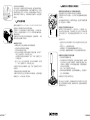
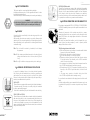
3 手轮操作
通常情况下,手轮在电动操作过程中不会转动。
即使转动,实心手轮上没有任何凸起物,因此不会对操作者构成伤
害风险。
而且,对于大扭矩的执行器来说,扭矩限制系统还提供了多重保
护。
SQ4 到 SQ15:
这类执行器配有手动离合手轮。
要手动操作执行器,请一边旋转手轮一边将其拉出,实现手轮的机
械啮合。
要使手轮脱开,只需朝向执行器体,将手轮推回即可。
SQ100,SQ250 到 SQ1000:
此类执行器均配备电动优先型自动离合手轮。手动操作执行器时,
旋转手轮离合器旋钮,将箭头对准箱体上的三角符号即可(必要时
稍微转动手轮,以便离合器啮合)。当电机启动时,手轮自动返回
到脱离位置。
警告
在防爆执行器安装和调试之前,还请仔细阅读TMS1132
特别说明。

4 5
Chinese
SQ25/SQ60/SQ80 型号:
这些执行器中,部分配有可离合的中间齿轮。通过拨动离合器拨
杆,电机即可与齿轮系统物理脱离。手动手轮操作完毕后,记住要
把电机离合复位。否则,在启动后,电机就会持续运行并发热,直
到电机热保护开关动作为止,如果反复发生这种情况,就会造成电
机损坏。
4 电气连接和初检
如果执行器配有 INTELLI+®, INTEGRAL+, POSIGAM, MINIGRAL 或 MINIGAM
控制装置,请参考相应的说明手册进行接线。
其它情况下,执行器的所有电子元器件均连接至一个公共端子板。
打开机壳,将电缆从电缆接口 (M20). 穿入,具体的端子编号系统,
请参考接线图。
扭矩和行程开关必须和用户的控制系统接好(见接线样例),以防
将来造成执行器或阀门的损坏。.
必须检查以下各项:
a)
确保电源电压与执行器铭牌上刻印的数据相符。
b) 检查所有电缆接口是否正确紧固。
c) 用手将阀门转到半开位置。
d) 进行电动开阀操作,检查电机旋转方向是否正确。用手按下“
开阀”行程限位开关,电机应停止运行。
以同样的方法检查电动关阀命令,以及“关阀”行程限位开关
工作是否正常。
e) 除 SQ4 到 SQ15之外的其他型号:进行电动开阀操作。用手按
下“开阀”扭矩限位开关,电机应停止运行。
以同样的方法进行电动关阀操作,检查“关阀”扭矩限位开关工作
是否正常。
本阶段如发现故障,则请检查整个接线。
为提高工作条件的安全性,我们建议立即切断电源,尤其是对扭矩
输出超过300 N.m. 的执行器,更应如此。
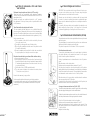
5 机械限位与行程限位开关的设定
机械限位相关说明与功能介绍(仅限角行程执行器):
这些机械限位可防止手轮操作过程中发生过行程现象。
这些限位既可安装于执行器上,也可安装于角行程蜗轮蜗杆齿轮箱
上(如有)。
执行器和齿轮箱均按照90°行程供货和检验。通过调节机械限位螺
栓,可进行最大± 2°的微调。
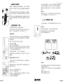
行程限位开关相关说明与功能介绍:
操作限位开关的凸轮组件位于一个圆柱体上,无需拆解。各凸
轮之间可相互独立设置,白色和黑色凸轮一般用于开阀和关阀
方向行程限位开关,其它则留给选配的附加限位开关 ( 2 或 4 )使
用。
凸轮设定方法:
a)
将螺丝刀插入按钮的槽内(按钮上的色圈与待设定的凸轮同
色)。
b) 轻轻下压,让凸轮脱离锁定位置。
c) 转动螺丝刀,将凸轮旋转到能够触发限位开关为止。
d) 松开螺丝刀,确保按钮回到原位,从而将凸轮锁定到所设位置。
机械限位和行程限位开关的设定步骤:
a)
将机械限位螺栓旋松2圈
b) 手动操作将阀门打到关阀位置。对角行程执行器来说,如果尚
未完成关阀,就已达到了机械限位,则表明行程已超出了所允
许的最大2°调整范围,切勿试图超越此限制,应重新调整执行
器与阀门的安装位置。
c) 设定“关阀”行程限位开关的凸轮。
d) 顺时针旋转机械限位螺栓,直到有机械接触为止。然后旋松1.5
圈,用锁定螺母锁定。
按照相同的方式进行开阀限位设定。
进行电动全开全关操作。必须确保电机停在行程限位开关设定位
置,而不是机械限位设定位置(继续转动手轮,检查到机械限位是
否还有额外行程)。

6 7
Chinese
6 扭矩限位开关的设定
重要事项:
伯纳德控制执行器的扭矩限制开关,在设计上只提供瞬
时接触,但可按照要求,在执行器上装配能保持这种接触的继电
器。
执行器的设定和测试均应按照订单中要求的扭矩进行。如未规定扭
矩,则执行器在供货时,扭矩弹簧设定为最大输出(参见技术手
册)。
如果必要,可通过调整扭矩弹簧压紧螺母,重新调整这一扭矩限
制。通过压紧或松开螺母,即可增大或减小扭矩限制。具体请与我
们联系。
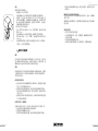
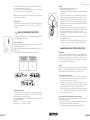
7 位置反馈电位计(选配)
执行器位置信号反馈电位计由行程凸轮组驱动。
电位计无机械限位,并且在行程起点和终点各有一段零电阻区(或
称死区)。0%位置对应阀门关闭,100%对应阀门开启。
电路板安装版本
在将电位计组件安装到开关板上时,要先卸下凸轮组顶端的位置指
示盘,然后将电位计卡好,再将其拧到圆柱支架上面,最后再将位
置指示盘拧回。.
调整“
0%
位置”螺钉可以设定电位计的零点。
令执行器到达关阀位置,
在端子
16
和
17
之间测量电阻值。
找到带“
0%
位置”标记的面板,捏住它正下方的小齿轮,同时调
节电位计螺钉,直到阻值超过
0
欧姆并开始逐渐增加,然后向回调
节,直到电阻值尽可能地接近
0
欧姆。
令执行器到达开阀位置,记下对应
100%
位置的阻值。
然后回到关阀位置,检查电阻是否为对应0%位置的一个接近0的可
重复数值。.
圆柱支架安装版本 (SQ4 到 SQ15)
在安装电位计组件时,首先将支架拧到安装板上,然后将驱动小齿
轮啮合到凸轮上面。
在调整电位计阻值时,先用扳手松开螺母,然后转动电位器,直到
达到所需的信号为止。
在设定
0%
时,将执行器打到关阀位置。
在端子
16
和
17
之间测量电阻值。
转动电位计,直到阻值超过
0
欧姆并开始逐渐增加,然后向回调
节,直到电阻值尽可能地接近
0
欧姆。
设定完毕后,重新拧紧螺母。
͐㏫ݢ
ఇ㏫ݢ
̵㏫ݢ
供电电压
直流电压(伏)
最大允许负载
欧姆
12 150
24 750
30 1050
令执行器到达开阀位置,记下对应
100%
位置的阻值。然后回到关
阀位置,检查电阻是否为对应
0%
位置的一个接近
0
的可重复数值。
注意:如果执行器配有两只电位计,则各电位计之间是相互独立设
定的。
信号反向:
要改变信号变化方向,将执行器端子板上的电位计接线反向即可
(如:正常连接顺序为
16/17/18
,反向则为
18/17/16
)。
8 «TAM» 位置变送器(选配)
TAM 变送器将输出一个与阀门角度位置成线性比例的0/4到20mA信
号。
电气连接
参考执行器所附接线图。也可参照如下典型接线举例。
过滤或稳定的电源应在12至32伏的范围内提供。
最大容许欧姆负载值参考下表 :
信号反向
标准执行器提供的
TAM
变送器,其信号都是从关到开逐渐增加,标
准开阀方向是逆时针方向。
如果需要反方向信号,只要将面板上电位计附近的
2
根跳线做如下
设定即可:
正常信号: 跳线设定为
1-3
和
2-4
反向信号: 跳线设定为
1-2
和
3-4

8 9
Chinese
特别存放环境潮湿时更应如此(除另行规定外,标准电压均为交
流230伏)。
配备有电子元件的执行器的存储:
电子元件长期存放不用,其故障风险会有所加大。因此,这种做法
非常不可取。
如果确实有必要长期存放,则强烈建议在使用执行器之前将电路板
返厂检测。
存放后的控管:
a)
对电气设备进行外观检查,
b)
手动操作微动开关、按钮、选择器等,确保机械功能正常,
c)
检查手轮操作,
d) 检查润滑脂的粘度是否正常,
e) 如果执行器配有加油嘴,则记住要补充一些新鲜润滑脂。
设定
将毫安表接在负载电路上。
-
始终要从0/4mA开始调节。
-
令执行器到达与 0/4mA相对应的位置(标准情况下是关阀位置)。
- 找到带“0%位置”标记的面板,捏住它正下方的小齿轮,同
时调节电位器螺钉,直到输出电流达到最小值。向回调节电位
器,直到电流值开始逐渐增加,然后再次向回调节,在达到上
面确定的最小值时立即停止。
此时电位计位于行程起点。
- 然后,调节TAM 上的标有“0/4mA”的调节螺钉,使电流尽可能
接近0/4 mA。
- 令执行器到达与20mA相对应的位置(标准情况下是开阀位置)。
- 调节TAM 上标有“20mA”的螺钉,直到毫安表上刚好显示为
20mA 为止。
- 然后回到关阀位置,检查信号电流是否显示为对应 0%位置的一
个接近 0/4 mA的可重复数值。
9 维护和存储说明
维护
执行器安装与密封正确时无需特殊维护。每年检查一次电机功
能,确保腔体内没有冷凝水。如果环境潮湿,为避免冷凝,伯
纳德电动执行器在内部安装有抗冷凝的电热电阻。
存储
执行器内部有电气设备以及采用润滑脂进行润滑的齿轮组,尽管有
全天候的防护机壳,但如果不能正确存放,依然有可能造成氧化、
卡死或其它损坏。.
执行器的库房存储
a)
执行器应存放在有遮雨棚的清洁干燥的地方,避免温度大幅度
变化。切勿将其直接放在地上。
b) 对带有加热电阻器的执行器,建议将加热电阻器接好并通电,
特别存放环境潮湿时更应如此(除另行规定外,标准电压均为
交流230伏)。
c) 检查进线口临时密封盖是否封好。检查保护盖和机箱是否盖
好,确保全天候密封。
执行器已安装,尚待接线
如果执行器安装完毕后,预计较长一段时间再进行电气接线,则
:
a) 目视检查电气盒盖和电缆接口的密封情况。
b) 用塑料防护薄膜盖住执行器。
c) 对带有加热电阻器的执行器,建议将加热电阻器接好并通电,

SQ100/SQ250/SQ400
10 11
English
SQ25/SQ60/SQ80 models:
Some of these actuators are equipped with declutchable intermediate
gears. By moving the clutch lever, the motor is physically disengaged from
the gears. Once the manual handwheel operation has been completed,
do not forget to clutch the motor back. Otherwise, once started-up,
it would run and heat up until the motor thermal protection switch closes.
If repeated, these conditions can generate a motor breakdown .
4 ELECTRICAL CONNECTIONS AND PRELIMINARY TESTS
If the actuator is equipped with INTELLI+®, INTEGRAL+, POSIGAM, MINIGRAL
or MINIGAM commands, please report to the specific documentation for wi-
ring details.
Otherwise, all components of the actuator are wired to a common
terminal strip. Remove the cover and pass the cables through the cable
glands (M20). Refer to the wiring diagram for details on the terminals
numbering system.
Both torque and travel limit switches must be integrated into your
control system (see wiring examples) in order to prevent potential
damage to the actuator or valve.
The following points must be checked:
a)
Make sure that power supply voltage is in accordance with the data
engraved on the actuator nameplate,
b)
Check that all cable glands are correctly tightened,
c)
Move the valve manually to an half-open position,
d)
Operate an electrical opening and check that the motor rotates
in the right direction. Press manually on the «OPEN» travel limit
switch ; the motor should stop.
In the same way, check that the closing electrical command as well as
the «CLOSED» travel limit switch are working correctly,
e)
All models except SQ4 to SQ15: operate an electrical opening. Press
manually on the «OPEN» torque limit switch ; the motor should
stop.
In the same way, operate an electrical closing check that
the «CLOSED» torque limit switch is working correctly,
If any misfunction was detected at this stage, please check the overall
wiring.
For safer working conditions, we recommend that the power supply now
be switched off especially if the actuator output max. torque exceeds
300 N.m.
1 SAFETY INFORMATION
This device complies to current applicable safety standards.
Installation, maintenance and use of this apparatus will have to be done
by skilled and trained staff only.
Please read carefully the whole document prior to mounting and starting-up.
2 ASSEMBLY
Actuator should be secured directly to the valve using proper bolts or via
a proper interface.
After assembly, the actuator can operate in any position. However, cable
glands should not be oriented upwards (loss of water tightness) and the
motor will preferably not be positioned at the bottom (potential internal
condensation trap)
Note 1 : do not handle the actuator by handwheel, it could damage
the gearworm.
Note 2 : if the actuator was delivered mounted on the valve, the basic
settings should have been done. In this case, refer to § 3,4 and
9 only.
Note 3 : see §.9 for details on storage precaution prior to starting-up.
3 HANDWHEEL OPERATION AND DECLUTCHING
In general, the handwheel does not turn during electrical operation.
Even if turning, the solid handwheel does not have any protruding part
and therefore does not present any risk of any kind for the operator.
Moreover, for the actuators with the highest torque, the torque limit sys-
tem brings an additional level of protection.
SQ4 to SQ15:
These actuators are equipped with a manually declutchable handwheel.
To operate manually the actuator, turn while pulling the handwheel
in order to mechanically engage it.
To declutch the handwheel, just push it back towards the actuator body.
SQ100, SQ250 to SQ1000:
These actuators are provided with an automatic declutching handwheel,
with motor drive priority. In order to operate manually the actuator, turn
the arrow of the handwheel clutch button in front of the triangular sign
on the housing (it might be necessary to turn the handwheel by a few
degrees to release the claws). When the motor starts, it returns automati-
cally into declutched position.
WARNING
For explosionproof actuators, please also read carefully the special
instructions TMS1132 prior to mounting and starting-up

12 13
English
6 SETTING OF TORQUE LIMIT SWITCHES
IMPORTANT: the torque limit switch design of Bernard Controls actua-
tors gives a short duration contact only. On request, relays holding this
contact maintained can be fitted into the actuator.
Actuators are set and tested in accordance with the torque stated
on orders. If no torque is specified, the actuator is supplied with torque
springs set to the maximum output (refer to our catalogue technical da-
tasheets).
If necessary, this torque setting can be readjusted by rotating the nuts
which compress the torque springs. So the torque can be increased
or decreased by tightening or loosening the nuts. Please consult us.
7 POSITION FEEDBACK POTENTIOMETER (OPTION)
The potentiometer used for actuator signal feedback is driven by the travel
cam block system.
The potentiometer has no mechanical stop and has a non-resistive area
(dead zone) at both the beginning and end of track.
0% position corresponds to a closed valve. 100% to an open valve.
Circuit board mounted version
To mount the potentiometer device on the switch plate, clip it without
the position indicator on the camblock and screw it on the support
column. Screw the position indicator back.
Setting of potentiometer zero is achieved thanks to the «0% postion»
screw.
Drive the actuator to the closed position.
Resistance value is measured between terminals 16 and 17.
Hold the pinion located just under the plate with the «0% position»
marking while driving the potentiometer screw. Adjust the potentiometer
so that the resistance value exceeds 0 Ohm and regularly increases then
turn backwards to reach a value as close to 0 Ohm as possible.
Drive the actuator to the open position and write down the resistance
value corresponding to the 100% position.
Come back to the closed position and check that, for the 0% position, the
resistance shows a close to zero repeatable value.
On support column mounted version (SQ4 to SQ15)
To mount the potentiometer device, screw the support column on the mounting
plate and engage the driving pinion into the camblock wheel.
To adjust the potentiometer resistance value, loosen the nut with the wrench
and rotate potentiometer until the signal requested is archieved.
To set the 0%, drive the actuator to the closed position.
Resistance value is measured between terminals 16 and 17.
Rotate the potentiometer so that the resistance value exceeds 0 Ohm
and regularly increases then turn backwards to reach a value as close to
0 Ohm as possible.
Retighten nut after setting.
5 SETTING OF MECHANICAL STOPS AND TRAVEL
LIMIT SWITCHES
Mechanical stops description and function (1/4 Turn only):
These items avoid any over-travelling during handwheel operations.
The stops can be positioned either on the actuator itself or on the 1/4 Turn
worm gearbox if any.
Actuators and gears are supplied and tested for a 90° operation.
Fine adjustment of the stop screws position is possible within a limit
of ± 2° maximum.
Travel limit switches description and function:
The cams operating the limit switches are on a cylindrical block which
does not require any disassembly. Each cam can be set independently of
the others. The white and black cams are for open and close travel limits.
The other ones are for additional limit switches for signalisation (2 or 4).
How to operate the cams:
a)
Put a screwdriver in the slot of the button encircled by the same
color as the cam to be set,
b)
Press lightly to disengage the cam of locked position,
c)
By turning the screwdriver rotate the cam to the position in which
it can trip the limit switch,
d)
Remove screwdriver and ensure that the button has come back to
its original position, thus locking the cam in chosen place.
Procedure of mechanical stops and travel limit switches setting:
a)
Loosen stop screws by 2 turns.
b)
Manually drive the valve to the closed position. If mechanical stops
are reached before the valve closing is completed, it means that the
2° maximum adjustment tolerance has been exceeded ; do not try
to go beyond this limit.
c)
Set the cam of the «CLOSED» travel limit switch.
d)
T urn stop screws clockwise to the mechanical contact, reloosen
1.5 turn, and secure by lock nut.
Proceed in the same way in open position.
Perform complete electrical valve opening and closing operations.
It is mandatory that the motor stops on the travel limit switch and not
on the mechanical stop (check available extra travel to the stop with
handwheel).

14 15
English
Settings
Connect a milliampermeter at the place of burden.
-
Always start by adjusting the 0/4mA.
-
Drive actuator to the position corresponding to the 0/4 mA (closed
in standard),
-
Hold the pinion located just under the plate with the «0% position»
marking while driving the potentiometer screw. Adjust the poten-
tiometer so that the output current reaches a minimum value. Turn
backwards until the current value regularly increases then turn
backwards again and stop as soon as the minimum value determined
here above has been reached.
The potentiometer is then positioned at the very beginning of its track.
-
Then, use the TAM adjustment screw marked as «0/4mA» to adjust
the current to a value as close to the 0/4 mA as possible.
-
Drive actuator to the position corresponding to the 20 mA (open
in standard),
-
Turn the screw marked «20mA» in order to read exactly 20 mA
on the milliampermeter.
-
Come back to the closed position and check that, for the 0% position,
the signal current shows a close to 0/4 mA and repeatable value.
9 MAINTENANCE AND STORAGE INSTRUCTIONS
Maintenance
If actuator is correctly mounted and sealed, no special maintenance is
required. Check once a year function of motor and make sure that switch
compartment is condensation free. If environment is humid, in oder to
avoid condensation BC electric actuator have installed anti-condensa-
tion heater resistance inside the enclosure.
Storage
The actuator includes electric equipment as well as grease lubricated gear
stages. In spite of the weatherproof enclosure, oxydising, jamming and
other alterations are possible if actuator is not correctly stored.
Actuators stored in a stock room
a)
The actuators should be stored under a shelter, in a clean and
dry place and protected from wide temperature variations. Avoid
placing the actuators directly on the floor.
b)
For actuators equipped with an heating resistance, it is recom-
mended to connect and power supply it especially if the storage
area is humid (standard 230 VAC, unless other specification).
c)
Check that the temporary sealing plugs of the cable entries are well
in place. Make sure that the covers and the boxes are well closed
to ensure weatherproof sealing.
Actuators installed but waiting for electrical connection
If a long period of time is expected between the actuator mounting and
the electrical wiring works :
a)
Visually check the tightness of electrical box cover and cable glands.
b)
Cover the device with a plastic protective film.
c)
For actuators equipped with an heating resistance, it is recom
Drive the actuator to the open position and write down the resistance
value corresponding to the 100% position.
Come back to the closed position and check that, for the 0% position, the
resistance shows a close to zero repeatable value.
Note: If actuator is equipped with 2 potentiometers, each potentiometer
is set independently of the other.
Signal inversion:
To inverse the signal variation direction, invert potentiometer wires
on the actuator terminal board (e.g. for a connection on 16/17/18, invert
16 and 18).
8 «TAM» POSITION TRANSMITTER (OPTION)
The TAM transmitter delivers a 0/4 to 20 mA signal linearly proportional
to the angular position of the valve.
Electric connections
Refer to the wiring diagram supplied with the actuator. See also some
typical wiring examples below.
Filtered or stabilised power supply should be provided within the 12 to
32 VDC range.
Maximum admissible ohmic load values are given in the table :
Signal direction inversion
The TAM transmitter, when supplied with a standard actuator, provides
a signal that rise from close position to open position, the standard
opening direction being counter-clockwise.
If an opposite signal variation is required, simply move 2 jumpers on the board
near the potentiometer.
Direct signal : jumpers on 1-3 and 2-4
Reversed signal : jumpers on 1-2 and 3-4
Energy Supply
DC (VOLT)
Max. admissible
load Ohm
12 150
24 750
30 1050

16 17
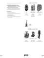
TAM
位置变送器
Position Transmitter
MINIGAM+ - MINIGRAL+
单相电机
简易控制主板
One phase actuator
electronic controls
INTEGRAL+ - POSIGAM+
一体化控制箱
Electronic controls
摇臂系统
Lever systems
SQ & ST INTELLI+®
智能执行器
Intelligent actuators
REGULATION / MODULATING
高负载 & 高精度
High duty & precision
FQ
安全复位执行器
Failsafe spring-return actuators
SQ 系列配件 / SQ RANGE ACCESSORIES
其他产品系列 / OTHER PRODUCTS RANGES
mended to connect and power supply it especially if the storage area
is humid (standard 230 VAC, unless other specification).
Storage of actuators equipped with electronic components:
Long term storage of electronic components which are not in service increases
the malfunction risk. This practice is therefore highly unadvisable.
If a long term storage is absolutely necessary, we strongly recommend
a revision of the electronic boards in our factory before actuator usage.
Control after storage:
a)
Visually check the electric equipment,
b)
Operate manually the microswitches, buttons, selectors, etc., to insure
the correct mechanical function,
c)
Operate apparatus manually,
d)
Verify the correct grease consistency,
e)
For actuators equipped with grease nipple, remember to complete
with some fresh grease.

18 19
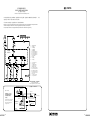
电源接线举例 / EXAMPLES OF POWER SUPPLY WIRING
☙䌛ஔ䯲ݜ⩡ᱦᣑ㏫
䌛ᐬڟ
⛀ஔ
☙ߔ㐓⩡ஔ
☙ߔ㐓⩡ஔ
⛀ஔ
䌛ᐬڟ
⩡ქ
⠘⿷⮰⩡ᱦᣑ㏫⯾
∔ᘻ
ࢁⰤ⩡ᱦ喏⩡ქஔܲᐬӇᏀȠ
(*) 针对预接线 SQ 型号,请参阅下一页的控制板设计举例
(*) for pre-wired SQ models, see examples of control panel design
on next page
非预接线版本 / not pre-wired version(*)
图例 / Legend : C1 = 接触器开 / contactor open ;
C2 = 接触器关 / contactor close
三相
3 PHASES
单相
1 PHASE
EEX E D
Connection
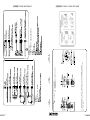
内部接线图 / INTERNAL WIRING DIAGRAMS
䔵䙹
⩡ᱦ
ߌ☙⩡䭧
⩡ᱦ☙ԉ័
ᐬ߇ⴕ䭼ѹ
ڟ߇ⴕ䭼ѹ
ᐬ㵸⼷䭼ѹ
ڟ㵸⼷䭼ѹ
ᐬ䭰ߌ㵸⼷䭼ѹ
ڟ䭰ߌ㵸⼷䭼ѹ
∔ᘻ
䒘ऽ
ᐬ喝䔲ᬢ䦴喞ڟ喝䶦ᬢ䦴
⩡ѹ䃍
じθ⩡ѹ䃍
ѹ㒚ऄ䔭ஔ
ಷण5".
͐㏫
͐㏫ᝂ̵㏫
䬖◥ᣑ㼒喋⩡ᱦ䓼㵸ᠳᴳ喌
∔ᘻ
߇ⴕ䭼ѹᐬڟ
̹䔮⩔κ0"ಷणȠछ䔵㷱㜖ԉᠭᐬڟȠ
∔ᘻ
㵸⼷䭼ѹᐬڟ
Ӈԉᠭ⮰ᣑ㼒Ƞ

备忘/ NOTES
20 21
开阀/Open
关阀/Closed
E1 : Circuit breaker+ fuse
E2 : Thermal relay
C1 : OPENING Contactor
C2 : CLOSING Contactor
C3 : DEFAULT Contactor
FCO : OPEN travel limit switch
FCF : CLOSE travel limit switch
LEO : OPEN torque limit switch
LEF : CLOSE torque limit switch
LT : motor thermal protection
TR : Transformer
B1 : Opening push button
B2 : Closing push button
默认/Defaut
无扭矩限位开关接线
Torque limit default acknoledgement
如需设置为扭矩关阀,请与我们联系。
Stop on torque limit switch
in the closing direction : please consult us.
例1 用行程限位开关停止开阀或关阀,扭矩限位开关用于安全保护(扭矩限位开关触发动作后需手动复位)。 本图
适用于整个SQ系列,SQ4 到 SQ15 除外(参见例2)。
对于SQ4 到 SQ15执行器,无扭矩限位开关,仅使用图中A侧部分。
Example 1 - Stop on travel limit switch on closing and opening directions, torque limit switch in safety action with
manual reset. Diagram valid for the entire SQ range(excepted SQ4 à SQ15) (cf. example 2).
For SQ4 to SQ15 actuators, not equipped with torque limit switch : side A of the diagram only.
执行器
Actuator
控 制 盘 设 计 样 例
CONTROL PANEL SAMPLE DESIGN
执行器位于中间位置
Actuators are represented in an intermediate position
Stop
停止
E1 : 断路器 + 熔断器
E2 : 热继电器
C1 : 开阀接触器
C2 : 关阀接触器
C3 : 故障接触器
FCO : 开阀方向行程限位开关
FCF : 关阀方向行程限位开关
LEO : 开阀方向扭矩限位开关
LEF : 关阀方向扭矩限位开关
LT : 电机过热保护
TR : 变压器
B1 : 开阀按钮
B2 : 关阀按钮
ڟ䬬closed
ᐬ䬬open
ᝣᣑ㏫CUSTOMER WIRING
䬬ᐬOPEN
䬬ڟCLOSED
ࢁⰤ⩡⎼
Single phase power supply
10
11
⩡ქஔCapacitor
ន㵸ஔᣑ㏫ACTUATOR WIRING
1
2
4
3
5
ᐬ䬬OPEN
6
ߌ☙⩡䭧ஔ
Heating resistance
㵸⼷䭼ѹᐬڟ
Travel limit switches
ڟ䬬CLOSED
12
⩡ᱦ䓳☙ԉ័Motor thermal protection
ҷ Example 2
䶰ᣑ㏫ࢁⰤSQ4ݜSQ15ಷ
ន㵸ஔ㼒ࣽᐬ䬬সڟ䬬
ऽ㵸⼷䭼ѹᐬڟᬢ喏ន
㵸ஔֈ₎Ƞ
Pre-wired one phase SQ4 to SQ15
actuators. Stop on travel limit
switch on both opening and
closing directions.
NON VECTORISE

备忘/ NOTES 备忘/ NOTES
22 23

BERNARD CONTROLS
4 rue d’Arsonval - CS 70091 - 95505 Gonesse Cedex - France
Tel: +33.1. 34.07.71.00 - Fax: +33.1.34.07.71.01
E-mail: mail@bernardcontrols.com
Internet: http://www.bernardcontrols.com
BC GROUP
比利时
BERNARD CONTROLS BENELUX
布鲁塞尔
inquiry.belgium@bernardcontrols.com
inquiry.holland@bernardcontrols.com
Tel. +32 (0)2 343 41 22
中国
BERNARD CONTROLS CHINA
北京
inquiry.china@bernardcontrols.com
Tel. +86 (0) 10 6789 2861
法国
BERNARD CONTROLS FRANCE
戈内斯 (巴黎)
inquiry.france@bernardcontrols.com
Tel. +33 1 34 07 71 00
德国
BERNARD CONTROLS DEUFRA
特罗斯多夫
inquiry.germany@bernardcontrols.
com
Tel. +49 22 41 98 340
意大利
BERNARD CONTROLS ITALIA
米兰
inquiry.italy@bernardcontrols.com
Tel. +39 02 931 85 233
韩国
BERNARD CONTROLS KOREA
首尔
inquiry.korea@bernardcontrols.com
Tel. +82 2 553 69 57
中东
BERNARD CONTROLS MIDDLE-EAST
迪拜.
inquiry.middleeast@bernardcontrols.
com
Tel. +971 4 880 0660
金奈 - 印度
inquiry.india@bernardcontrols.com
Tel. +0091 9566204444
俄罗斯
BERNARD CONTROLS RUSSIA
莫斯科
inquiry.russia@bernardcontrols.com
+7 499 251 06 54
新加坡
BERNARD CONTROLS SINGAPORE
新加坡
inquiry.singapore@bernardcontrols.
com
Tel. +65 65 654 227
西班牙
BERNARD CONTROLS SPAIN
马德里
inquiry.spain@bernardcontrols.com
Tel. +34 91 30 41 139
美国
BERNARD CONTROLS Inc
休斯顿
inquiry.usa@bernardcontrols.com
Tel. +1 281 578 66 66
详尽的代理商和分销商信息
请访问
www.bernardcontrols.com
Exhaustive list of agents
and distributors on
www.bernardcontrols.com
-
 1
1
-
 2
2
-
 3
3
-
 4
4
-
 5
5
-
 6
6
-
 7
7
-
 8
8
-
 9
9
-
 10
10
-
 11
11
-
 12
12
-
 13
13


Bernard Controls SQ Range Installation & Operation Manual
- タイプ
- Installation & Operation Manual
他の言語で
- English: Bernard Controls SQ Range
関連論文
-
Bernard Controls ST Range Installation & Operation Manual
-
-
-
Bernard Controls FQ Range Installation & Operation Manual
-
-
-
-
その他のドキュメント
-
AEG CR193 ユーザーマニュアル
-
Danfoss Liquid level sensor Type AKS 4100 / AKS 4100U - Coaxial D14 version インストールガイド
-
 Hach NA5600 sc Na+ 取扱説明書
-
-
-
 Hach Accu4 ユーザーマニュアル
-
-
Schneider Electric TeSys Deca - Coil Overload Protection Module Instruction Sheet
-

