
DOC023.97.80356
Accu4
™
(T53, 8320)
01/2013, Edition 1
User Manual
用户手册

English...................................................................................................................................................................................................3
中文.......................................................................................................................................................................................................29
2

Table of contents
Specifications on page 3 Operation on page 18
General information on page 4 Maintenance on page 23
Installation on page 7 Troubleshooting on page 24
User interface and navigation
on page 17
Replacement parts and accessories
on page 27
Startup on page 18
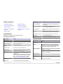
Specifications
Specifications are subject to change without notice.
Model 8320 turbidity sensor
Specification Details
Operational:
Flow rate 0.19 to 26.5 LPM (0.05 to 7 GPM)
Ambient conditions 0 to 60 °C (32 to 140 °F)
Sample temperature
range
0 to 60 °C (32 to 140 °F)
Pressure range 0–3.4 bar at 20 °C (0–50 psig at 68 °F)
Pressure drop 0.0001 bar at 0.36 LPM (0.0017 psig at 0.1 GPM)
Residence time 3.8 LPM (9.5 seconds at 1 GPM)
Air venting Integral bubble trap for 0.19 to 1.9 LPM (0.05 to
0.5 GPM) flows.
Installation of an external bubble trap and a restrictor
valve on the sensor outlet is recommended for flows
above 1.9 LPM (0.5 GPM) with air in the sample.
Refer to Use an external bubble trap on page 27.
Mechanical:
Light sources Two near-infrared (880 nm wavelength) LEDs
Specification Details
Power requirements 5 V supplied by the controller to the light sources
and detectors
Process connections ½–in. NPT female standard; adaptable to
3
/
8
–in. or
¼–in. NPT, barb or tube fittings
Wetted materials PVC, polycarbonate, polystyrene, PPO, nitrile and
Buna-N
Enclosure Molded fiber-glass-reinforced polyester (flame
retardant) with four brackets for surface mounting
Dimensions (W x D x H) 285 x 172 x 400 mm (11.21 x 6.79 x 15.75 in.)
Net weight 4.5 kg (10 lb) approximately
Certifications 15 year environmental friendly use period
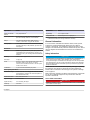
Model T53 controller
Specification Details
Operational:
Display Graphic dot matrix LCD, 128 x 64 pixels with LED
backlighting; 13 mm (½–in.) main character height;
3 mm (
1
/
8
–in.) auxiliary information character height;
menu screens contain up to six lines of text
Ambient conditions Operation: –20 to 60 °C (–4 to 140 °F); 0–95% relative
humidity, non-condensing
Storage: –30 to 70 °C (–22 to 158 °F); 0–95% relative
humidity, non-condensing
Pollution degree 2
Installation category II
Protection class I
Altitude 2000 m (6561 ft) maximum
English 3

Specification Details
Sensor-to-controller
distance
9 m (30 ft) maximum
1
Power requirements 90–130 VAC (115 VAC nominal) or 180–260 VAC
(230 VAC nominal), 50/60 Hz, 10 VA maximum
Relays Four electromechanical relays; SPDT (Form C)
contacts; 115/230 VAC, 5 A @ 30 VDC resistive
Analog outputs Two isolated 0.00–20.00 mA or 4.00–20.00 mA outputs
each with 0.004 mA (12–bit) resolution; up to 600 ohm
load capacity
Mechanical:
Enclosure NEMA 4X; polycarbonate face panel, epoxy-coated
cast aluminum door and case with four 13-mm (½–in.)
cable entry holes, nylon mounting bracket and stainless
hardware
Mounting Panel, surface or pipe mount
Net weight 2.3 kg (5 lb)
Fuses One type T, 80 mA, 250 V slow-blow fuse for the 230 V
line power circuits, 5 mm x 20 mm; one type T,
100 mA, 250 V slow-blow fuse for the 115 V line power
circuits, 5 mm x 20 mm
Certifications 15 year environmental friendly use period
Accu4 system performance:
Measurement range 0.000–100.0 NTU; auto-ranging and automatic decimal
point shift above 1.000 NTU and 10.00 NTU (same for
other measurement units)
Measurement units NTU, TEF, FNU or FTU
Signal averaging 0 to 60 seconds
System accuracy ±2% of reading, all ranges
Sensitivity 0.001 NTU
Specification Details
Repeatability 0.1% of span or better
Temperature drift Zero and span: 0.01% of span per °C
1
Contact the manufacturer if a longer distance is necessary.
General information
In no event will the manufacturer be liable for direct, indirect, special,
incidental or consequential damages resulting from any defect or
omission in this manual. The manufacturer reserves the right to make
changes in this manual and the products it describes at any time, without
notice or obligation. Revised editions are found on the manufacturer’s
website.
Safety information
N O T I C E
The manufacturer is not responsible for any damages due to misapplication or
misuse of this product including, without limitation, direct, incidental and
consequential damages, and disclaims such damages to the full extent permitted
under applicable law. The user is solely responsible to identify critical application
risks and install appropriate mechanisms to protect processes during a possible
equipment malfunction.
Please read this entire manual before unpacking, setting up or operating
this equipment. Pay attention to all danger and caution statements.
Failure to do so could result in serious injury to the operator or damage
to the equipment.
Make sure that the protection provided by this equipment is not impaired.
Do not use or install this equipment in any manner other than that
specified in this manual.
Use of hazard information
D A N G E R
Indicates a potentially or imminently hazardous situation which, if not avoided, will
result in death or serious injury.
4 English

W A R N I N G
Indicates a potentially or imminently hazardous situation which, if not avoided,
could result in death or serious injury.
C A U T I O N
Indicates a potentially hazardous situation that may result in minor or moderate
injury.
N O T I C E
Indicates a situation which, if not avoided, may cause damage to the instrument.
Information that requires special emphasis.
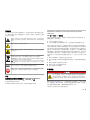
Precautionary labels
Read all labels and tags attached to the instrument. Personal injury or
damage to the instrument could occur if not observed. A symbol, if noted
on the instrument, will be included with a danger or caution statement in
the manual.
This is the safety alert symbol. Obey all safety messages that follow
this symbol to avoid potential injury. If on the instrument, refer to the
instruction manual for operation or safety information.
This symbol indicates that a risk of electrical shock and/or
electrocution exists.
This symbol indicates the presence of devices sensitive to Electro-
static Discharge (ESD) and indicates that care must be taken to
prevent damage with the equipment.
Electrical equipment marked with this symbol may not be disposed of
in European public disposal systems after 12 August of 2005. In
conformity with European local and national regulations (EU Directive
2002/96/EC), European electrical equipment users must now return
old or end-of-life equipment to the Producer for disposal at no charge
to the user.
Note: For return for recycling, please contact the equipment producer or supplier
for instructions on how to return end-of-life equipment, producer-supplied
electrical accessories, and all auxiliary items for proper disposal.
This symbol, when noted on the product, identifies the location of a
fuse or current limiting device.
This symbol indicates that the marked item requires a protective earth
connection. If the instrument is not supplied with a ground plug on a
cord, make the protective earth connection to the protective
conductor terminal.
Certification
Canadian Radio Interference-Causing Equipment Regulation,
IECS-003, Class A:
Supporting test records reside with the manufacturer.
This Class A digital apparatus meets all requirements of the Canadian
Interference-Causing Equipment Regulations.
Cet appareil numèrique de classe A répond à toutes les exigences de la
réglementation canadienne sur les équipements provoquant des
interférences.
FCC Part 15, Class "A" Limits
Supporting test records reside with the manufacturer. The device
complies with Part 15 of the FCC Rules. Operation is subject to the
following conditions:
1. The equipment may not cause harmful interference.
2. The equipment must accept any interference received, including
interference that may cause undesired operation.
Changes or modifications to this equipment not expressly approved by
the party responsible for compliance could void the user's authority to
operate the equipment. This equipment has been tested and found to
comply with the limits for a Class A digital device, pursuant to Part 15 of
the FCC rules. These limits are designed to provide reasonable
protection against harmful interference when the equipment is operated
in a commercial environment. This equipment generates, uses and can
radiate radio frequency energy and, if not installed and used in
accordance with the instruction manual, may cause harmful interference
to radio communications. Operation of this equipment in a residential
area is likely to cause harmful interference, in which case the user will be
required to correct the interference at their expense. The following
techniques can be used to reduce interference problems:
English
5

1. Disconnect the equipment from its power source to verify that it is or
is not the source of the interference.
2. If the equipment is connected to the same outlet as the device
experiencing interference, connect the equipment to a different
outlet.
3. Move the equipment away from the device receiving the interference.
4. Reposition the receiving antenna for the device receiving the
interference.
5. Try combinations of the above.
Product overview
D A N G E R
Chemical or biological hazards. If this instrument is used to monitor a
treatment process and/or chemical feed system for which there are
regulatory limits and monitoring requirements related to public health,
public safety, food or beverage manufacture or processing, it is the
responsibility of the user of this instrument to know and abide by any
applicable regulation and to have sufficient and appropriate
mechanisms in place for compliance with applicable regulations in the
event of malfunction of the instrument.
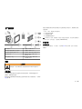
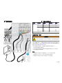
The Accu4 low-range turbidimeter system includes a Model
8320 turbidity sensor and Model T53 controller. Refer to Figure 1 and
Figure 12 on page 17. The system design meets the International
Standards for Measurement of Turbidity (ISO 7027) for FNU and
USEPA-approved GLI Method 2 for NTU.
This system is used to monitor the turbidity of potable water or filtered
water.
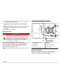
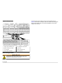
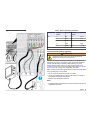
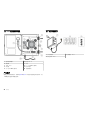
Figure 1 Model 8320 turbidity sensor overview
1 Calibration hose and funnel 6 Detectors (2x)
2 Terminal board 7 Door latch
3 Light sources (2x) 8 Inlet (½–in. NPT female)
4 Flow chamber 9 3-way value, internal
5 Outlet (½–in. NPT female) 10 Sensor cable
Product components
Make sure that all components have been received. Refer to Figure 2
and Figure 3. If any items are missing or damaged, contact the
manufacturer or a sales representative immediately.
6
English

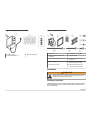
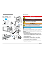
Figure 2 Turbidity sensor components
1 Turbidity sensor 3 Mounting screws (4x)
2 Mounting brackets (4x)
Figure 3 Controller components
1 Controller 6 Flat washers, ¼–in. ID (8x)
2 Sealing gasket for panel mount,
Neoprene
7 Hex nuts, M6 (8x)
3 Mounting foot (2x) for panel mount 8 Pan head screws, M6 x 1.0 x
20 mm (4x)
4 Mounting bracket 9 Pan head screws, M6 x 1.0 x
100 mm for pipe mount (4x)
5 Ground screw, green 10 Pan head screws, M6 x 1.0 x
150 mm for panel mount (4x)
Installation
W A R N I N G
Multiple hazards. Only qualified personnel must conduct the tasks
described in this section of the document.
Installation guidelines
Install the turbidity sensor as near as possible to where the controller is
to be installed. Contact the manufacturer if a distance longer than 9 m
(30 ft) is necessary.
English
7

Make sure that the ambient conditions of the installation location of the
turbidity sensor and controller are within specifications. Refer to
Specifications on page 3.
Install the turbidity sensor indoors or outdoors where there is little or no
ambient vibration. Install the controller in a location that is:
• Clean and dry where there is little or no vibration
• As far as possible away from sources of vibration
• As near as possible to the water source
• Protected from corrosive fluids
Note: If exposed to direct sunlight, the operating temperature of the controller may
increase above the specified limit. Direct sunlight may also decrease the display
visibility. If necessary, use a sun shield (1000G3088-001).
Mechanical installation
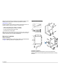
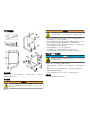
Sensor mounting
Install the turbidity sensor on a flat surface. Refer to the illustrated steps
in Figure 4. Mounting hardware is supplied by the user.
Figure 4 Sensor mounting
Controller mounting
Install the controller on a flat surface, panel or pipe (horizontal or
vertical). Refer to the instructions supplied with the controller mounting
hardware.
8
English

Electrical installation
W A R N I N G
Potential electrocution hazard. In order to maintain the NEMA/IP
environmental ratings of the enclosure, use only conduit fittings and
cable glands rated for at least NEMA 4X/IP66 to route cables in to the
instrument.
W A R N I N G
Potential Electrocution Hazard. Always disconnect power to the
instrument when making electrical connections.
• Put all wiring to the sensor and controller in ½-inch, grounded metal
conduit to protect the cable from moisture, electrical noise or
mechanical damage.
If only shielded cables are used, applicable strain reliefs or cable grips
are necessary. Accessory watertight cable grips (3H1091) and
locknuts (3H1230) are available from the manufacturer.
• Make sure that the diameter of the cables used is 4.3–11.4 mm (0.17–
0.45 in.) so that the cable strain reliefs hold the cables securely when
tightened.
• Do not put more than one cable in a cable strain relief.
• Close all unused cable entry holes with applicable plugs to keep out
moisture.
• Close all unused cable strain reliefs with rods or cables to keep out
moisture.
Electrostatic discharge (ESD) considerations
N O T I C E
Potential Instrument Damage. Delicate internal electronic components
can be damaged by static electricity, resulting in degraded
performance or eventual failure.
Refer to the steps in this procedure to prevent ESD damage to the
instrument:
• Touch an earth-grounded metal surface such as the chassis of an
instrument, a metal conduit or pipe to discharge static electricity from
the body.
• Avoid excessive movement. Transport static-sensitive components in
anti-static containers or packages.
• Wear a wrist strap connected by a wire to earth ground.
• Work in a static-safe area with anti-static floor pads and work bench
pads.
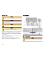
Wiring overview
Figure 5 shows the wiring connections and fuses for the controller.
English 9

Figure 5 Wiring overview
1 Analog output connections (2x) 5 AC input power connections
2 RS232 connection (not used) 6 Fuses (2x)
3 TTL connection 7 Relay connections (4x)
4 Sensor cable connections 8 Grounding strip
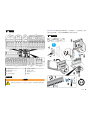
General wiring procedure
W A R N I N G
Potential Electrocution Hazard. Always disconnect power to the
instrument when making electrical connections.
Connect wiring to the controller as shown in the illustrated steps in
Figure 6. When wiring is complete, close the controller cover and tighten
all the cover screws in order to maintain the NEMA/IP environmental
ratings of the enclosure.
10 English

Figure 6 General wiring procedure
Wiring for power
D A N G E R
Electrocution hazard. Protective Earth Ground (PE) connection is
required.
D A N G E R
Electrical shock and fire hazards. Make sure to identify the local
disconnect clearly for the conduit installation.
W A R N I N G
Potential Electrocution Hazard. If this equipment is used outdoors or in
potentially wet locations, a Ground Fault Interrupt device must be
used for connecting the equipment to its mains power source.
N O T I C E
Install the device in a location and position that gives easy access to the
disconnect device and its operation.
Supply power to the controller with conduit or a power cable. Make sure
that a circuit breaker with sufficient current capacity is installed in the
power line. The circuit breaker size is based on the wire gauge used for
installation.
For installation with conduit:
• Install a local disconnect for the controller within 3 m (10 ft) of the
controller. Put a label on the disconnect that identifies it as the main
disconnect device for the controller.
• Make sure that the power and safety ground service drops for the
controller are 18–12 AWG.
• Connect equipment in accordance with local, state or national
electrical codes.
• Connect the conduit through a conduit hub that holds the conduit
securely and seals the enclosure when tightened.
For installation with a power cable, make sure that the power cable is:
• Less than 3 m (10 ft) in length
English
11

• Rated for at least 60 °C (140 °F) and applicable to the installation
environment
• Not less than 18 AWG with applicable insulation colors for local code
requirements
• A power cable with a three-prong plug (with ground connection) that is
applicable to the supply connection
• Connected through a cable gland (strain relief) that holds the power
cable securely and seals the enclosure when tightened
• Does not have a locking type device on the plug
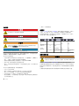
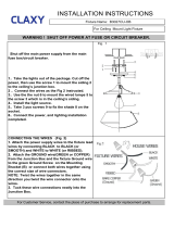
Wiring procedure
Refer to Table 1, Figure 5 on page 10 and General wiring procedure
on page 10 to connect the controller to power. Supply power to only one
terminal (terminal 3 or 4). Connect line power using the standard three-
wire connection arrangement.
Do not put the sensor cable (and interconnect cable, if used) in the same
conduit with power wiring. Electrical noise may interfere with the sensor
signal.
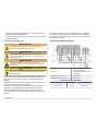
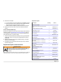
Table 1 AC power wiring information
Input voltage Terminal Description
Color—North
America
Color—EU
115 VAC,
single phase
3 Hot
Black Brown
230 VAC,
single phase
or split phase
4 Hot
115 or
230 VAC
2 Neutral (N) White Blue
— Protective
Earth (PE)
grounding
strip
Green Green with
yellow stripe
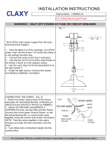
Connect the sensor cable
W A R N I N G
Potential Electrocution Hazard. Always disconnect power to the
instrument when making electrical connections.
Refer to General wiring procedure on page 10, Figure 7 and Table 2 to
connect the sensor cable to the controller.
Cut the sensor cable to the shortest applicable length before it is
connected to the controller to prevent unnecessary electrical noise that
may interfere with the sensor signal. Keep the cable away from motors
or other equipment that may give off electrical or magnetic fields.
Directly connect the sensor to the controller to remove potential
problems caused by wet environments and a junction box.
12 English

Figure 7 Connect the sensor cable
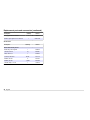
Table 2 Sensor cable wiring information
Terminal block Terminal
number
Wire color Terminal
number
Wire color
TB-1 12 Red 18 Brown
13 Violet 19 Grey
14 Green 20 Blue
15 White 21 Black
16 Yellow 22 Orange
Connect the inner shield wires to the grounding strip.
Connect the analog outputs (optional)
W A R N I N G
Potential Electrocution Hazard. Always disconnect power to the
instrument when making electrical connections.
The controller contains two isolated 0.00-20.00 mA or 4.00-20.00 mA
analog outputs (Output 1 and Outputs 2) that represent the measured
turbidity. Use the analog outputs for analog signaling or to control
external devices. Refer to Figure 5 on page 10 and General wiring
procedure on page 10 to connect the analog outputs. Refer to Configure
the analog outputs on page 19 for configuration information.
Make connections with twisted-pair shielded wire and connect the shield
to the grounding strip in the controller.
• Do not connect the shield at both ends of the cable.
• Use of non-shielded cable may result in radio frequency emission or
susceptibility levels higher than allowed.
• Maximum loop resistance is 600 ohms.
Notes:
• The analog outputs are isolated from the other electronics, but are not
isolated from each other.
English
13

• The analog outputs are self-powered. Do not connect to a load with
voltage that is independently applied.
• The analog outputs cannot be used to supply power to a 2-wire (loop-
powered) transmitter.
Connect the relays (optional)
W A R N I N G
Potential Electrocution Hazard. Always disconnect power to the
instrument when making electrical connections.
W A R N I N G
Potential Electrocution Hazard. Power and relay terminals are
designed for only single wire termination. Do not use more than one
wire in each terminal.
W A R N I N G
Potential fire hazard. Do not daisy-chain the common relay
connections or jumper wire from the mains power connection inside
the instrument.
C A U T I O N
Fire hazard. Relay loads must be resistive. Always limit current to the
relays with an external fuse or breaker. Obey the relay ratings in the
Specifications section.
The controller contains four electromechanical relays (Relay A, B, C and
D) that are opened or closed by the measured turbidity or diagnostics.
Refer to Configure the relays on page 19. The relay outputs are not
powered.
Refer to General wiring procedure on page 10, Figure 8 and Table 3 to
connect the relays to a control or alarm device.
The relay terminals accept 18–12 AWG wire (as determined by load
application). Wire gauge less than 18 AWG is not recommended.
When switching large inductive loads (e.g., motors and pumps) or
currents higher than 5 A, use an auxiliary relay to extend the controller
relay life.
Use the relays at either all high voltage (greater than 30 V-RMS and
42.2 V-PEAK or 60 VDC) or all low voltage (less than 30 V-RMS and
42.2 V-PEAK, or less than 60 VDC). Do not configure a combination of
both high and low voltage.
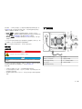
Figure 8 Typical wiring configuration
1 Relay A 5 Control or alarm device, non-
inductive load switching
2 Relay C 6 Control or alarm device, inductive
load switching
3 Capacitor (0.1 µF, 600 V) 7 100–230 VAC
4 Resistor (100 ohms, 1 watt) 8 Phase 2 or N
Table 3 Relay wiring information
NC COM NO
Normally closed Common Normally open
14 English

Connect the TTL input (optional)
W A R N I N G
Potential Electrocution Hazard. Always disconnect power to the
instrument when making electrical connections.
The controller has one TTL input that lets the user hold or transfer the
analog outputs and the relays. Refer to Figure 5 on page 10. The TTL
input feature function is the same as the output state (HOLD, XFER or
ACTIVE) selected during the last calibration.
• HOLD—The analog outputs and relays are held at their present
values/on-off states.
• XFER (transfer)—The analog output values and relay states are
changed to the selected Set Transfer values/states. Refer to
Configure the analog outputs on page 19 and Configure the relays
on page 19.
• ACTIVE—The analog outputs and relays represent the measured
turbidity. The TTL input is disabled.
To apply a TTL hold or transfer, locally or remotely connect the two TTL
terminals. When this connection is broken, the applied hold or transfer
releases.
Note: The TTL input feature is disabled during calibration and system diagnostic
tests that are started by the user.
Plumbing
Plumb the sensor
D A N G E R
Fire hazard. This product is not designed for use with flammable
liquids.
N O T I C E
When metal fittings are used, do not over tighten them onto the plastic inlet or
outlet fitting of the sensor or damage to the plastic fitting may occur.
Install the sensor in an "in line" process configuration using a closed loop
piping arrangement or in a sample bypass line configuration using an
open drain piping arrangement. Refer to Figure 9 and Figure 10.
Procedure notes:
• Bushings may be used to decrease to a smaller tubing size. Barb or
tube fittings may be installed.
• Use larger sample tubing for applications in which sediment buildup
commonly occurs. A faster flow rate helps flush sediment through the
sensor.
• Use Teflon tape to seal the inlet and outlet connections. Do not use
pipe dope or other liquid sealants.
English 15

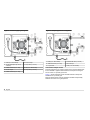
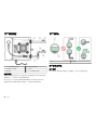
Figure 9 Closed-loop piping arrangement
1 Outlet (½–in. NPT female) 6 Process output
2 To open atmosphere (to vent for
calibration)
7 3-way valve (½–in. IPS)
3 Isolation ball valve (½–in. IPS) 8 Inlet (½–in. NPT female)
4 Process output 9 3-way valve (½–in. IPS)
5 Isolation ball valve (½–in. IPS)
Figure 10 Sample bypass line configuration
1 Outlet (½–in. NPT female) 4 Isolation ball valve (½–in. IPS)
2 Isolation ball valve (½–in. IPS) 5 Process input
3 To open drain 6 Inlet (½–in. NPT female)
Connect the sample stream
Install the sample line into a larger process pipe to minimize interference
from air bubbles or pipeline bottom sediment. A sample line that goes
into the center of a process pipe is best.
Figure 11 shows examples of good and bad methods of sample line
installation into a process pipe.
Keep the sample line as short as possible to decrease analysis delay.
Sediment can collect in long sample lines.
16
English

Figure 11 Sampling methods
1 Air 2 Sample flow
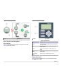
User interface and navigation
User interface
Figure 12 shows the display and keypad of the Model T53 controller.
Table 4 gives the key functions.
Figure 12 Display and keypad
1 Display 2 Keypad
Table 4 Key functions
Key Function
MENU Go to the Main Menu screen and cancel the procedure
to change a setting
ESC Go back one menu level or cancel the procedure to
change a setting
ENTER Confirm a menu selection or confirm changes to a
setting
RIGHT and LEFT
arrows
Toggle between the two Measure screens or change the
cursor position
UP and DOWN
arrows
Select a menu, or change a setting or value
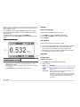
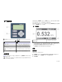
Display description
Figure 13 shows the Measure screen. To go to the Measure screen,
push MENU and then ESC.
English
17

Note: If the keypad is not used within 30 minutes, except during calibration or while
specific controller Test/Maintenance functions are used, the display automatically
goes to the Measure screen.
From the Measure screen, push the RIGHT or LEFT arrow to toggle
between the two Measure screens. The second Measure screen is for
Service use only.
To adjust the display contrast, push and hold ENTER and
simultaneously push the UP or DOWN arrow while the Measure screen
shows.
Figure 13 Measure screen
1 Relay status
1
3 Analog Output 1 value (mA)
3
2 Turbidity reading
2
1
The relays that are energized show. For example, if Relay A and C are
energized, "RELAY: A C" shows. The relay status flashes when a relay
overfeed timer has expired.
2
If the reading is not within the measurement range of the controller, a series of
"+" or "–" shows.
3
Push the DOWN arrow to see the Analog Output 2 value (mA).
Startup
Select the language
Select the display language (default = English).
1. Push MENU and select CONFIGURE>LANGUAGE.
2. Use the UP and DOWN arrows to select the language.
3. Push ENTER.
Start the flow
Start the flow of sample through the flow chamber.
1. Turn the 3-way valve handle of the sensor to the OPERATE position.
2. If the recommended isolation valve is used downstream of the
sensor outlet, open the isolation valve slowly to start the flow.
3. Measure the flow at the outlet. Make sure that the flow is within the
flow range shown in Specifications on page 3.
Operation
Configuration
Configure the sensor
1. Push MENU and select CONFIGURE>SENSOR.
2. Select an option.
Option Description
SELECT
UNITS
Select the measurement units shown—NTU (default), TEF,
FNU or FTU.
SET FILTER Set the amount of time for measurement averaging—0 to
60 seconds (30 seconds = default).
For example, if the value is set to 30 seconds, the turbidity
value shown is updated every 30 seconds and the value is
the average of the turbidity values during the previous
30 seconds.
18 English

Option Description
PULSE
SUPPRESS
Set the pulse suppression feature to on or off. ON—Pulse
suppression is enabled. Pulse suppression prevents
unstable readings caused by external interference (e.g.,
entrained gas bubbles in the sample and electromagnetic
interference). Pulse suppression identifies a pulse change
(reading spike) as a temporary upset and does not show
most of the pulse change. OFF—Pulse suppression is
disabled.
ENTER NOTE Select the alphanumberic text that is shown on the top line
of the Measure screen (default = ACCU4). The text can be
a maximum of 8 characters. The selected digit is in square
brackets. Push the UP or DOWN arrow to change the value
of the selected digit. Push the RIGHT arrow to select the
next digit.
3. Push ENTER to confirm.
Configure the analog outputs
If the analog outputs of the controller are used, configure the analog
outputs. The two analog outputs of the controller represent the
measured turbidity.
1. Push MENU and select CONFIGURE>SET OUTPUT 1 (or 2).
2. Select a configuration option.
Option Description
SET 4mA (or
0mA) VALUE
Select the turbidity value that represents 4 mA (or 0 mA)
on the analog output—0.00 (default) to 100.00.
SET 20mA
VALUE
Select the turbidity value that represents 20 mA on the
analog output—0.00 to 100.00 (default).
Note: If the same turbidity values are set for 0/4 mA and
20 mA, the analog outputs automatically go to and stay at
20 mA.
SET
TRANSFER
Set the transfer value of the analog output—4 (or 0) to
20 mA (default = 20 mA). During calibration, the analog
outputs can be held, transferred or kept active. When
transfer is selected, the analog outputs are held at the
transfer value.
Option Description
SET FILTER Set the amount of time for analog output averaging—
0 (default) to 60 seconds.
For example, if the value is set to 30 seconds, the value of
the analog outputs is updated every 30 seconds and the
value is the average of the analog output values during the
previous 30 seconds.
Note: The analog output filter time setting is added to the
sensor filter time setting which increases the time delay
between measurement updates.
SCALE
0mA/4mA
Set the analog output range of the analog output. 0mA—
0 to 20 mA. 4mA (default)—4 to 20 mA.
3. Push ENTER to confirm.
Configure the relays
If the relay connections of the controller are used, configure the relays.
The four relays of the controller are energized or de-energized (opened
or closed) by the measured turbidity or diagnostics.
1. Push MENU and select CONFIGURE>SET RELAY (A, B, C or D).
2. Select a configuration option.
Option Description
SET
FUNCTION
Set the relay to function as a control, alarm or status relay.
ALARM (default)—a relay with separate high and low
alarm points and deadbands that operates in response to
the measured turbidity. CONTROL—a relay with phasing,
setpoint, deadband and overfeed timer that operates in
response to the measured turbidity. STATUS—a relay that
operates only in response to selected system diagnostic
conditions.
English 19

Option Description
SET
TRANSFER
Set the transfer state of the relay—DE-ENERGIZED
(default) or ENERGIZED. During calibration, the relays
can be held, transferred or kept active. When transfer is
selected, the relays are held at the transfer state.
ACTIVATION This menu changes depending on the selected function of
the relay (alarm relay, control relay or status relay). Refer
to SET FUNCTION.
A table for each relay type follows. Refer to the applicable
table for the configuration options.
Alarm relay
Option Description
LOW ALARM Set the low alarm value—0.00 (default) to 100.00. The
relay is energized when the measured turbidity is lower
than the low alarm value.
HIGH ALARM Setsthe high alarm value—0.00 to 100.00 (default). The
relay is energized when the measured turbidity is higher
than the high alarm value.
LOW
DEADBAND
Set the measured turbidity range in which the relay stays
on after the measured turbidity increases above the low
alarm value—0.00 (default) to 10.00.
HIGH
DEADBAND
Set the measured turbidity range in which the relay stays
on after the measured value decreases below the high
alarm value—0.00 (default) to 10.00.
OFF DELAY Set the delay time for the relay to switch off—0 (default)
to 300 seconds.
ON DELAY Set the delay time for the relay to switch on—0 (default)
to 300 seconds.
Control relay
Option Description
PHASE Set the phase for the relay to high or low. HIGH (default)
—The relay is energized when the measured turbidity is
higher than the setpoint. LOW—The relay is energized
when the measured turbidity is lower than the setpoint.
SET SETPOINT Set the setpoint (measured turbidity) value at which the
relay is energized—0.00 to 100.00 (default).
DEADBAND Set the measured turbidity range in which the relay stays
on—0.00 (default) to 10.00. For a high phase relay, this is
the range after the measured value decreases below the
setpoint. For a low phase relay, this is the range after the
measured value increases above the setpoint.
OVERFEED
TIMER
Set the time to limit how long the relay can stay on—
0.0 (default) to 999.9 minutes. For more details on
overfeed timer operation, refer to Overfeed timer for
control relays on page 20.
OFF DELAY Set the delay time for the relay to switch off—0 (default) to
300 seconds.
ON DELAY Set the delay time for the relay to switch on—0 (default) to
300 seconds.
Status relay
Option Description
SET
STATUS
TYPE
Set the status relay type. ALL (default)—The relay is
energized when there is a "Fail" or a "Chamber Unknown"
condition or a "Chamber Dirty" condition. WARN—The relay is
energized only when there is a "Chamber Dirty" condition.
FAIL—The relay is energized only when there is a "Fail" or a
"Chamber Unknown" system condition. Refer to
Troubleshooting on page 24 for the list of conditions.
3. Push ENTER to confirm.
Overfeed timer for control relays
The overfeed timer setting prevents a condition that keeps the measured
turbidity higher than the setpoint or deadband setting (e.g., damaged
20
English
ページが読み込まれています...
ページが読み込まれています...
ページが読み込まれています...
ページが読み込まれています...
ページが読み込まれています...
ページが読み込まれています...
ページが読み込まれています...
ページが読み込まれています...
ページが読み込まれています...
ページが読み込まれています...
ページが読み込まれています...
ページが読み込まれています...
ページが読み込まれています...
ページが読み込まれています...
ページが読み込まれています...
ページが読み込まれています...
ページが読み込まれています...
ページが読み込まれています...
ページが読み込まれています...
ページが読み込まれています...
ページが読み込まれています...
ページが読み込まれています...
ページが読み込まれています...
ページが読み込まれています...
ページが読み込まれています...
ページが読み込まれています...
ページが読み込まれています...
ページが読み込まれています...
ページが読み込まれています...
ページが読み込まれています...
ページが読み込まれています...
ページが読み込まれています...
-
 1
1
-
 2
2
-
 3
3
-
 4
4
-
 5
5
-
 6
6
-
 7
7
-
 8
8
-
 9
9
-
 10
10
-
 11
11
-
 12
12
-
 13
13
-
 14
14
-
 15
15
-
 16
16
-
 17
17
-
 18
18
-
 19
19
-
 20
20
-
 21
21
-
 22
22
-
 23
23
-
 24
24
-
 25
25
-
 26
26
-
 27
27
-
 28
28
-
 29
29
-
 30
30
-
 31
31
-
 32
32
-
 33
33
-
 34
34
-
 35
35
-
 36
36
-
 37
37
-
 38
38
-
 39
39
-
 40
40
-
 41
41
-
 42
42
-
 43
43
-
 44
44
-
 45
45
-
 46
46
-
 47
47
-
 48
48
-
 49
49
-
 50
50
-
 51
51
-
 52
52


他の言語で
- English: Hach Accu4 User manual
関連論文


その他のドキュメント
-
Extech Instruments MO100 ユーザーマニュアル
-
OTT MF pro Basic ユーザーマニュアル
-
 T'nB DCC70PLP データシート
-
Bernard Controls SQ Range Installation & Operation Manual
-
Mettler Toledo 5000TOCi Sensor 取扱説明書
-
 CLAXY B8878DU インストールガイド
-
 CLAXY B3027CU-OB ユーザーマニュアル
-
 CLAXY B8878DU ユーザーマニュアル
-
Vaisala MHT410 ユーザーマニュアル
-
GF Ball Valve Type 546 Pro ユーザーマニュアル


