
概述
General Description
The Shure ANI4IN Audio Network Interface converts 4 analog audio channels
into independent digital audio channels on a Dante™ network. Microphone,
auxiliary, and line-level devices are supported, with adjustable gain and +48V
phantom power for each channel. In networked conferencing systems, the
Audio Network Interface provides a simple way to connect analog equipment
onto the audio network, such as wireless microphones. The web application
controls signal routing and channel settings from any computer connected
to the same network.
Model Variations
ANI4IN-XLR: Four XLR inputs (balanced audio only)
ANI4IN-BLOCK: Four 6-pin block connector inputs (balanced audio and
logic connections)
Hardware and Installation
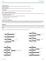
Hardware
Block Connector Model:
sig/clip
power
reset
PoE
network
network audio
encryption
1
1
2
2
3
4
3
4
INPUT
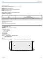
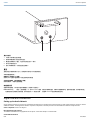
XLR Model:
1/32©2017 Shure Incorporated
ANI4IN

reset
PoE
INPUT
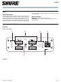
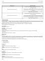
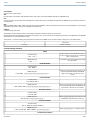
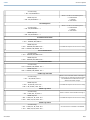
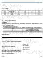
① Input Signal Clip Indicators
Each indicator corresponds to a single input channel. If the LED turns red, attenuate the level from the source device to prevent clipping at the input stage.
Analog and digital gain adjustments are made through the web application.
Audio Signal LevelLED State
less than -60 dBFSOff
-60 dBFS to -18 dBFSGreen
-18 dBFS to -6 dBFSYellow
-6 dBFS or moreRed
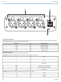
② Audio and Logic Inputs
Note: Logic connections are only featured on the block connector version
Block Inputs: Each input receives balanced audio and logic signals. Pin assignments are as follows:
Audio +
Audio -
Audio ground
Logic Mute (sent from microphone)
switch
Logic LED (received by microphone)
led
Logic ground
gnd
XLR Inputs: Each input receives a balanced audio signal. Pin assignments are as follows:
Ground
1
Positive
2
Negative
3
Shure IncorporatedANI4IN
2017/10/302/32

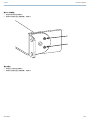
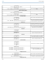
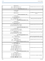
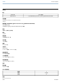
③ Chassis Ground Screw
Provides an optional connection for microphone shield wire to chassis ground
Note: only applies to block connector version
④ LED Indicators
Power: Power over Ethernet (PoE) present
Note: Use a PoE injector if your network switch does not supply PoE.
Network: Network connection active
Network Audio: Dante™ audio present on the network
Note: Error details are available in the event log in the web application.
Encryption: Not currently supported
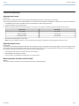
ActivityLED Status
No active signalOff
Device is operating successfullyGreen
Error has occurred. See event log for details.Red
⑤ Dante Network Port
Connects to a network switch to send Dante™ audio, while receiving Power over Ethernet (PoE) and data from the control software. See the Dante and net-
working section for additional information.
⑥ Reset Button
Resets the device settings back to the factory default.
乙太網路供電 (PoE)
乙太網路供電
本裝置需要 PoE 才能工作。它與 0 和 3 PoE 源均相容。
乙太網路供電的工作方式如下:
• 一台提供 PoE 的網路交換機
• 一個 PoE 注射裝置
安裝和機架固定
有兩個固定解決方案可用於安裝:
CRT1 19" 最多支援 3 個裝置;可固定於機架中或桌面下
支援單一裝置以固定在桌面下
固定裝置
使用固定硬體套件中包含的螺釘以固定。可朝任一方向固定。根據下列圖表,在適當的孔中從底部插入螺釘:
如圖所示對齊孔洞,在單一裝置固定托盤中固定單一裝置
Shure IncorporatedANI4IN
3/322017/10/30

如圖所示對齊孔洞,在 19" 機架托盤中最多固定三個裝置。
機架耳片設定
可將最多 3 個的組合固定在單一 19 英吋機架空間中。可調節的機架耳片支援標準設備機架中或桌面下的安裝固定。
Shure IncorporatedANI4IN
2017/10/304/32

標準 19" 機架固定
1. 使用指向前方的固定孔對齊耳片。
2. 安裝將耳片支撐在托盤上的兩個螺釘,如圖所示。
桌面下固定
1. 使用指向上方的固定孔對齊耳片。
2. 安裝將耳片支撐在托盤上的兩個螺釘,如圖所示。
Shure IncorporatedANI4IN
5/322017/10/30

桌面下安裝
1. 以桌面下的所需位置支撐托盤
2. 使用鉛筆標記桌面下固定孔洞的位置。
3. 鑽出要使用螺釘的 4 個孔。托盤中的孔洞直徑為 7.1 毫米。
4. 將元件安裝到托盤中
5. 使用 4 顆螺絲安裝,以將托盤固定在桌面下
重設
重設按鈕位於後側面板的小孔內。使用迴紋針或其他小工具按壓該按鈕。
有兩個硬體重設功能:
網路重設(按住按鈕 4-8 秒鐘)
將所有 Shure 控制和音訊網路 IP 設定重設為出廠預設值
完全重設出廠設定(按住按鈕超過 8 秒鐘)
將所有網路和恢復為出廠預設值。
軟體重設選項
若要簡單恢復設定,而不進行完整的硬體重設,請使用下列選項之一:
Reboot Device在(設定 > 出廠預設值)中,有Reboot Device按鈕,若裝置中斷網路連接,可簡單向裝置循環供電。重新啟動裝置後,會保留所有設定。
若要將音訊設定恢復為出廠預設值(排除设备名称、IP 設定和密碼),請選擇Load Preset並選擇預設設定預設。
Signal Flow and Connections
Setting up the Audio Network
Shure networked conferencing systems are comprised of Microflex Advance microphones and network interfaces, which operate entirely on a Dante™ network.
Additional hardware, including network switches, computers, loudspeakers, and audio processors are described in the hardware component index.
Shure components shown in this diagram:
Microflex Advance Microphones
The MXA910 and MXA310 are equipped with Dante outputs, and connect directly to a network switch.
Audio Network Interfaces
Shure IncorporatedANI4IN
2017/10/306/32

The interfaces are used to connect analog devices such as loudspeakers and analog microphones to the network.
ANI4IN: Converts 4 analog signals (separate XLR and block connector models available) into Dante™ digital audio signals.
ANI4OUT: Converts 4 channels of Dante™ audio from the network into analog signals.
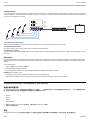
This diagram shows the entire signal path through a networked conference system. Signals from the near end and far end are exchanged through an audio
processor connected to a phone system, or through a computer connected to the internet. Analog microphones connect to the network through the Shure ANI4IN,
while loudspeakers connect through the Shure ANI4OUT.
Shure IncorporatedANI4IN
7/322017/10/30

This diagram shows Microflex Advance components in context, with two rooms communicating through video codecs.
Controlling Hardware and Audio Over the Network
Audio and hardware settings are managed through a computer connected to the same network.
Shure IncorporatedANI4IN
2017/10/308/32

Shure Hardware and Audio
Each Microflex Advance component has a web application which provides mixing and configuration tools to optimize sound quality.
Expanded Control for Analog Devices
Analog devices that are connected to the network through a Shure network interface (ANI4IN/ANI4OUT) benefit from additional remote control: Volume levels,
equalization, and signal routing are managed through the web application. For example, adjusting loudspeaker volume or muting a wired microphone, which
would normally be done from the hardware, can now be controlled remotely over the network.
Dante™ Signal Routing
Signal routing between devices is managed through Dante Controller software, provided by Audinate™ .
Shure IncorporatedANI4IN
9/322017/10/30

Connections and Signal Flow
① MX396 (Dual-element)
In addition to running the audio signals, this boundary microphone features three additional wire leads for logic connections. This allows the switch on the microphone
to send a logic mute signal to other equipment on the network, and to receive a logic LED control signal.
② MX392
In addition to running the audio signal, this boundary microphone features three additional wire leads for logic connections. This allows the switch on the microphone
to send a logic mute signal to other equipment on the network, and to receive a logic LED control signal.
Shure IncorporatedANI4IN
2017/10/3010/32

③ ULX-D Receiver
Wireless microphones connect to the network interface through the balanced analog outputs on the receiver.
④ Network Switch
Provides connectivity between the Dante™ audio network and the computer that controls signal processing and routing.
⑤ Computer
A computer or tablet running the web application provides independent gain control for each connected device.
Input: Analog (4 XLR or Block Connectors)
Each Audio Network Interface has 4 analog inputs with variable analog gain for line, auxiliary, and microphone-level signals. Examples of devices to connect to
the network with the Audio Network Interface:
• Wireless microphone systems
• Wired installed microphones (logic functions supported by block connector model)
• Computers or mobile devices used for presentations
• Other playback devices
Output: Dante™ Digital Audio
Connect the Dante™ output to a network switch with a network cable. A single network cable delivers all 4 channels of audio onto the network, and carries
Power over Ethernet (PoE) to power the device. Use Dante™ Controller to route audio channels from the Audio Network Interface to the appropriate network
destination. Any of the signals may be routed to multiple destinations, to provide local reinforcement while simultaneously delivering audio to the far end.
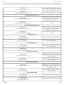
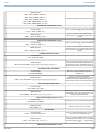
Summing
The Audio Network Interface provides channel summing to combine input signals and send them over a single Dante™ channel. This makes it possible to send
all channels to a device with a limited amount of Dante™ receiver channels. Mixer functionality does not change; audio channels are simply sent as one combined
signal.
Note:When summing is enabled, a limiter is activated to prevent signal overloading. The limiter never applies to the direct outputs, and only affects the summed
signal.
To enable, select one of the summing options in the toolbar at the top of the mixer in the channels tab.
1 + 2 + 3 + 4
1
2
3
4
3
4
1 +2
1
2
3
4
2
1
3 + 4
1
2
3
4
1 + 2
3 + 4
1
2
3
4
Shure IncorporatedANI4IN
11/322017/10/30

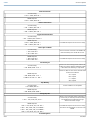
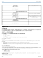
Example Scenario
A common application that requires summing is a video conference where there are multiple microphones. When a device (a computer running conferencing
software and Dante™ Virtual Soundcard, for example) only supports 1 or 2 Dante™ receiver channels, the Audio Network Interface combines the input signals
to transmit as a single Dante™ channel.
reset
PoE
INPUT
1 + 2 + 3 + 4
1
2
3
4
① Summed analog audio channels
When the 4 analog audio channels are summed, each of the Dante™ transmit channels includes all of the input signals.
② Single Dante audio channel
One Dante™ signal is sent over the network, which contains all 4 summed channels.
③ Connection to computer
A computer that is running limited number of Dante™ channels with Dante™ Virtual Soundcard, receives all audio on a single channel. This audio is sent to
the far end.
Encryption
Audio is encrypted with the Advanced Encryption Standard ( AES -256), as specified by the US Government National Institute of Standards and Technology
(NIST) publication FIPS-197. Shure devices that support encryption require a passphrase to make a connection. Encryption is not supported with third-party
devices.
To activate encryption:
1. Open the 设置 menu and select the 總述 tab.
2. Select the Enable Encryption checkbox.
3. Enter a passphrase. All devices must use the same passphrase to establish an encrypted connection.
Important: For encryption to work:
• Encryption must be universally enabled or disabled on all connected Shure devices
• AES67 must be disabled in Dante Controller to turn encryption on or off. AES67 encryption is currently not supported.
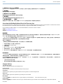
Software Installation, Management, and Security
軟體安裝和裝置發現
Shure Web Device Discovery 應用程式用於存取適用於 Shure 裝置的 。如果加密設定不同,將在接收機液晶顯示面板上顯示 可以在網路瀏覽器中開
啟,提供綜合的裝置管理手段。和裝置聯網的任何電腦均可透過該應用存取 GUI。
• Chrome
• Safari
• Firefox
• Internet Explorer
1. 安裝 Shure Web Device Discovery 應用程式,該程式可從 www.shure.com 取得
2. 按兩下元件以開啟介面。
存取
Shure Web Server Discovery 應用程式可透過基於 Web 的圖表化使用者介面搜尋網路中的所有舒爾裝置。執行這些步驟,安裝軟體並存取 :
Shure IncorporatedANI4IN
2017/10/3012/32

① 安裝 Shure Discovery 應用程式
從 www.shure.com 下載並安裝 Shure Discovery 應用程式。這樣可以在電腦上自動安裝所需的 Bonjour 裝置檢測工具。
② 連接網路
確保電腦和硬體位於相同的網路中。
③ 啟動 Discovery 應用程式
應用程式將顯示採用圖表化使用者介面的所有舒爾裝置。
④ 識別硬體
按兩下裝置可在網路瀏覽器中開啟圖表化使用者介面 (GUI)。
⑤ 給裝置設定標籤 (建議)
將裝置的 DNS 名稱加入書籤,可以在不需要 Shure Discovery 應用程式的情況下存取圖表化使用者介面。
Accessing the Web Application without the Discovery App
If the Discovery application is not installed, the web application can be accessed by typing the DNS name into an internet browser. The DNS name is derived
from model of the unit, in combination with the last three bytes (six digits) of the MAC address, and ending in .local.
Format Example: If the MAC address of a unit is 00:0E:DD:AA:BB:CC, then the link is written as follows:
ANI4IN: http://ANI4IN-aabbcc.local
ANI4OUT: http://ANI4OUT-aabbcc.local
固件更新
固件是在每個功能控制元件中的嵌入式軟體。定期開發的新固件版本中包含附加功能和效能增強部分。若要享受設計改進帶來的優勢,可利用「Shure Update
Utility」工具上傳和安裝新版本的固件。軟體可以從網站 http://www.shure.com 中下載。
當 Shure MXW 音訊網路介面連接 Shure Olympus 元件時,它們的固件必須在更新 MXW 音訊網路介面固件之前在一台裝置上進行更新。嘗試同時更新所
有裝置將導致介面在固件更新後重新啟動,將遺失與其他聯網元件的連接。
按照以下步驟更新固件:
確保裝置在更新期間具有穩定的網路連接。在完成更新之前,請勿關閉裝置電源。
1. 將裝置和電腦接入同一網路(設為相同子網)。
2. 下載和安裝 Shure Update Utility。
3. 開啟應用程式。
4. 按一下 Check For Updates... 檢視可供下載的新固件版本。
5. 選擇所需的固件,按Download下載至固件庫中。
6. 從Update Devices標籤中選擇新固件,然後按下Send Updates...開始固件更新,這會重寫裝置現有固件。
固件版本要求
Shure MXW 裝置採用多通訊協定的網路,這些協定同時確保裝置正常工作。推薦的最佳做法是所有 Shure MXW 裝置採用相同的版本。若要檢視網路中每
個裝置的固件版本,可開啟元件使用者介面,然後查看 Settings>About.
Shure 裝置的固件格式為 MAJOR.MINOR.PATCH。(例如在固件「1.6.2」中,1 為主要固件等級,6 為次要固件等級,2 為補丁固件等級。)在相同子網工作
的裝置至少應擁有相同主要和次要版本號。
• 主要版本號不同的裝置不相容。
• 補丁固件版本號的差異可能會產生不希望出現的不一致性。
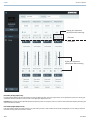
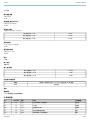
Channel Utilities
+48V (Phantom Power)
Delivers + 48V phantom power to the selected channel
Polarity Reverse
Each channel has a checkbox to reverse the polarity of the input signal.
Analog Gain
Adjusts the gain to optimize input signal level before the analog audio is converted to a digital audio.
Digital Gain
Adjusts the digital signal level to optimize the signal strength over the network.
Mute Groups
Check the 靜音群組 box to add the channel to a group. Muting any channel within the mutes all channels in the group.
Fader Groups
Check the 化音器群組 box to add the channel to a group. All faders within the group are linked, and move together when a single fader is adjusted.
Shure IncorporatedANI4IN
13/322017/10/30

Logic Switch Indicator
Illuminates when a switch logic signal is received by the Audio Network Interface from a microphone.
Note: only applies to block connector model.
Logic LED Indicator
Illuminates when an LED logic signal is received by the Audio Network Interface through the network from a control system.
Note: only applies to block connector model.
Parametric Equalizer
Maximize audio quality by adjusting the frequency response with the parametric equalizer.
Common equalizer applications:
• Improve speech clarity
• Reduce noise from HVAC systems or video projectors
• Reduce room irregularities
• Adjust frequency response for reinforcement systems
Setting Filter Parameters
Adjust filter settings by manipulating the icons in the frequency response graph, or by entering numeric values. Disable a filter using the check-box next to the
filter.
Filter Type
Only the first and last band have selectable filter types.
Parametric: Attenuates or boosts the signal within a customizable frequency range
Low Cut: Rolls off the audio signal below the selected frequency
Low Shelf: Attenuates or boosts the audio signal below the selected frequency
High Cut: Rolls off the audio signal above the selected frequency
High Shelf: Attenuates or boosts the audio signal above the selected frequency
Frequency
Select the center frequency of the filter to cut/boost
Gain
Adjusts the level for a specific filter (+/- 30 dB)
Q Width
Adjusts the range of frequencies affected by the filter. As this value increases, the bandwidth becomes thinner.
Shure IncorporatedANI4IN
2017/10/3014/32

Equalizer Applications
Conferencing room acoustics vary based on room size, shape, and construction materials. Use the guidelines in following table.
Suggested SettingsEQ Application
Add a high shelf filter to boost frequencies greater than 1 kHz by 3-6 dBTreble boost for improved speech intelligibility
Add a low cut filter to attenuate frequencies below 200 HzHVAC noise reduction
Shure IncorporatedANI4IN
15/322017/10/30

Suggested SettingsEQ Application
Identify the specific frequency range that "excites" the room:
1.Set a narrow Q value
2.Increase the gain to between +10 and +15 dB, and then experiment with
frequencies between 1 kHz and 6 kHz to pinpoint the range of flutter echoes
or sibilance
3.Reduce the gain at the identified frequency (start between -3 and -6 dB) to
minimize the unwanted room sound
Reduce flutter echoes and sibilance
Identify the specific frequency range that "excites" the room:
1.Set a narrow Q value
2.Increase the gain to between +10 and +15 dB, and then experiment with
frequencies between 300 Hz and 900 Hz to pinpoint the resonant frequency
3.Reduce the gain at the identified frequency (start between -3 and -6 dB) to
minimize the unwanted room sound
Reduce hollow, resonant room sound
Custom Presets
Use presets to quickly save and recall settings. Up to 10 presets can be stored on each device to match various seating arrangements. A preset saves all device
settings except for the , IP Settings, and Passwords. Importing and exporting presets into new installations saves time and improves workflow. When a preset
is selected, the name displays above the preset menu. If changes are made, an asterisk appears next to the name.
Note: Use the default settings preset to revert to the factory configuration (excludes , IP Settings, and Passwords).
Open the presets menu to reveal preset options:
save as preset:
Saves settings to the device
load preset:
Opens a configuration from the device
import from file:
Downloads a preset file from a computer onto the device. Files may be selected through the browser or dragged into the import window.
export to file:
Saves a preset file from the device onto a computer
Event Log
Event Log
The event log provides a detailed account of activity from the moment the device is powered on. The log collects up to 1,000 activity entries and time-stamps
them relative to the last power cycle. The entries are stored in the internal memory, and are not cleared when the device is power-cycled. The Export feature
creates a CSV (comma separated values) document to save and sort the log data.
Refer to the log file for details when troubleshooting or consulting with Shure Systems Support.
To view the event log:
1. Open the Help menu
2. Select View Event Log
Severity Level
Information
An action or event has been successfully completed
Warning
An action cannot be complete, but overall functionality is stable
Error
A problem has occurred that could inhibit functionality.
Log Details
Description
Provides details on events and errors, including IP address and subnet mask.
Time Stamp
Power cycles:days:hours:minutes:seconds since most recent boot-up.
Event ID
Indicates event type for internal reference.
Tip: Use the filter to narrow down results. Select a category heading to sort the log.
Shure IncorporatedANI4IN
2017/10/3016/32

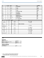
Levels and Metering
Adjusting Input Levels
Input Levels
Before you begin, verify that levels from the analog devices with adjustable output levels are operating at nominal levels.
The analog gain adjusts the level of the audio signal before it is converted from analog to digital. It is adjustable in 3 dB increments, with up to 51 dB total gain.
1. Set the Metering to Pre-fader in the toolbar at the top of the workspace to monitor analog signal levels
2. Select the analog gain value to open the fader
3. Match the analog gain setting to the incoming signal level. Use the gain range markers on the fader to apply the appropriate amount of gain:
Gain RangeSource Level
0 to +9 dBLine (+4 dBu)
+9 to +21 dBAuxiliary (-10 dBV)
+21 to +51 dBMicrophone (varies)
4. The meters should peak between -18 and -9 dB.
Note: Leaving some additional headroom is a recommended to prevent clipping if mobile devices will be plugged into particular channels.
Adjusting Output Levels
Output Levels
Output levels are controlled by the Digital Gain (dB) fader. Always adjust the input gain (analog) before the output gain (digital). In most cases, setting the analog
gain correctly results in an appropriate output level. Sources that have a quiet signal, such as a microphone with low sensitivity, may need someDigital Gain
(dB) applied. If adjustments to the Digital Gain (dB) fader are required, follow these steps:
1. Set the Metering to Post-fader in the toolbar at the top of the workspace.
2. Adjust theDigital Gain (dB) fader as needed.
3. If using summing, use the Digital Gain (dB) faders to mix the channel levels.
Metering Options (Pre-fader and Post-fader)
Metering
There are two modes for monitoring, for input and output signals to be monitored separately.
Shure IncorporatedANI4IN
17/322017/10/30

Analog gain adjustment
(affects pre-fader metering)
Digital gain adjustment
(affects post-fader metering)
Pre-fader
Post-fader
Pre-Fader (Analog Input Level)
Pre-fader metering displays the signal level before it reaches the digital gain fader, so that input signal levels can be optimized for each channel. Analog gain
adjustments affect the meter when set to pre-fader, but the digital gain adjustments do not.
Important: If the incoming signal is adjustable (wireless microphone systems, for example), make sure it is at the nominal level before adjusting the analog gain
on the Audio Network Interface.
Post-Fader (Digital Output Level)
Post-fader metering displays the signal level at the very end of the signal chain, which includes both the analog and digital gain. Use this setting to meter the
levels that are being sent over the Dante™ network.
Shure IncorporatedANI4IN
2017/10/3018/32

Logic and Control Systems
Logic Applications
The block connecter model variation (ANI4IN-BLOCK) features three logic signal connections. Logic signals are converted into Ethernet command strings and
sent and received by any device (such as an echo canceller or control system) that supports Ethernet command strings.
In this diagram, Shure MX392 and MX396 Microflex
®
microphones are connected the audio network interface. The mute button on each microphone sends a
logic signal (switch) to mute other audio equipment. The microphones receive logic signals (LED) so that the microphone LED behavior reflects the state of the
entire audio system.
Shure IncorporatedANI4IN
19/322017/10/30

ANI4IN Command Strings
Command Strings
The device is connected via Ethernet to a control system, such as AMX, Crestron or Extron.
Connection: Ethernet (TCP/IP; select “Client” in the AMX/Crestron program)
Port: 2202
Shure IncorporatedANI4IN
2017/10/3020/32
ページが読み込まれています...
ページが読み込まれています...
ページが読み込まれています...
ページが読み込まれています...
ページが読み込まれています...
ページが読み込まれています...
ページが読み込まれています...
ページが読み込まれています...
ページが読み込まれています...
ページが読み込まれています...
ページが読み込まれています...
ページが読み込まれています...
-
 1
1
-
 2
2
-
 3
3
-
 4
4
-
 5
5
-
 6
6
-
 7
7
-
 8
8
-
 9
9
-
 10
10
-
 11
11
-
 12
12
-
 13
13
-
 14
14
-
 15
15
-
 16
16
-
 17
17
-
 18
18
-
 19
19
-
 20
20
-
 21
21
-
 22
22
-
 23
23
-
 24
24
-
 25
25
-
 26
26
-
 27
27
-
 28
28
-
 29
29
-
 30
30
-
 31
31
-
 32
32


