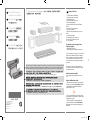
HP DesignJet 510 Printer series Assembly Instructions
- カテゴリー
- 印刷
- タイプ
- Assembly Instructions

© 2010 Hewlett-Packard Company
Inkjet Commercial Division
Camí de Can Graells 1-21 · 08174
Sant Cugat del Vallès
Barcelona · Spain
All rights reserved
Printed in XXX
EN
KO
ZHCN
ZHTW
JP
HP Designjet 510 printer series
Assembly and Set-Up Instructions
HP Designjet 510
HP Designjet 510
HP Designjet 510
HP Designjet 510
1 Check the Contents of the Package / / /
/
EN
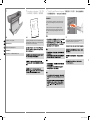
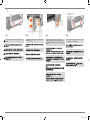
Contents of This Poster
1. Check Contents of the Package
2. Unpack the Main Components
3. Assemble the Stand
4. Attach the Stand to the Printer
5. Assemble the Paper Bin
6. Locate the Front-Panel Overlay and Pocket
Guide
7. Switch On, Choose Language
8. Insert Ink Cartridges
9. Replace Set-Up Printheads with Active Print-
heads
10. Load a Roll of Paper
11. Understand Printer Connections
12. Install and Connect a LAN Card
13. Set-up software.
The information on this poster applies to the
following HP products:
• HP Designjet 510 Series
• Stand and Paper Bin available as accessory.
If you are installing an accessory, such as a stand,
after the main installation has been completed,
use the instructions that came with the accessory.
If you are installing it at the same time as the
main installation, read the appropriate stages of
this Poster.
For accessory cards, see “Understand Printer
Connections” and the documentation that comes
with these accessories.
Read these instructions carefully...
and complete each stage before you start the
next.
What You Will Need to Do the Job
• Because some of the components of the printer
are bulky, you will need 2 or 3 people to lift them.
See the descriptions that follow for details—a
symbol like this is used:
• You are recommended to have a oor area of
approximately 6 square metres for unpacking and
assembling your printer.
• The time required to unpack, assemble and
set up the hardware is about 30 to 90 minutes,
depending on the model and components (e.g.
the stand).
x2
EN
KO
ZHCN
ZHTW
JP
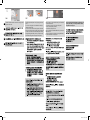
Check the items shown and notify your supplier if any are missing. Don’t open the items until you are prompted to do so on
this Poster. The packaging varies between models; there may be additional items in the box. These Assembly and Set-Up
Instructions, and the ‘Day-to-day’ package containing the Using your printer documentation CD, are supplied in the box.
이 조립 및 설치 방법과 프린터 사용 설명서 CD가 들어 있는 ‘Day-to-day’ 패키지는 상자에 들어 있습니다.
上述组装和设置说明,以及装有“使用打印机”文档 CD 的便携包,均可在包装箱内找到。
這些組件與設置的指示,以及「Using your printer」(如何使用印表機)文件 CD 所屬之「日常」套件,都將隨附於包裝中。
プリンタの前面を見て、緑色の印が付いている脚を右側に取り付けます。
ap.indd 1 9/30/2010 4:08:57 PM

KO
ZHCN
ZHTW
JP
x2
x2
x2
x2
ap.indd 2 9/30/2010 4:08:58 PM

EN
KO
ZHCN
ZHTW
JP
2:1
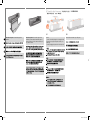
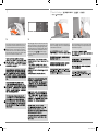
Remove:
- (E+/A0+-size model) The large box containing the stand
and paper bin. Two people may need to do this, as it’s
rather large.
- The foam packaging that protects the ends of the printer.
x2
The E+/A0+ size printer with stand and paperbin as
standard.
The D/A1-size printer with no stand or paper bin as
standard. If you have ordered a stand and paper bin
and are installing it now, follow these instructions, as for
a E+/A0+-size model.
2:2
Remove the foam restraints on top of the printer.
2 Unpack the Main Components / /
/ /
ap.indd 3 9/30/2010 4:09:00 PM

4+4=8
EN
KO
ZHCN
ZHTW
JP
2:3
For E+/A0+-size models and if you have the stand
accessory use the poster supplied with it, open the box
that contains the stand and the paper bin—it’s the large
box above the main printer body. –For models without a
stand, go to Stage 6: Locate the Front-Panel Overlay and
the Pocket Guide.
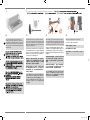
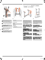
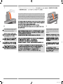
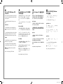
3:1
A screwdriver and 22 screws are provided in the stand
box: 16 screws to assemble the stand, 4 to attach it to the
printer, and 2 are spare. Do not try to remove the washers
from the screws. Note: All the screws are for the stand. The
basket does not need screws.
스탠드 상자에는 드라이버와 22 개의 나사가 들어 있습니
다. 스탠드를 조립하는 데 16 개, 프린터에 스탠드를 연결
하는 데 4 개, 그리고 2 개는 예비용입니다. 나사에서 와셔
를 제거하지 마십시오. 참고: 모든 나사는 스탠드용입니
다. 바스켓에는 나사가 필요 없습니다.
底座盒中有一个螺丝刀和 22 枚螺钉:其中 16 枚螺钉用
于组装底座,4 枚用 于将底座连接到打印机,剩下 2 枚螺
钉 是备用的。不要尝试从螺钉上取下垫圈。注:所有螺钉
都是用于底座的。纸筐的 安装不需要螺钉。
機架盒內附有螺絲起子和 22 顆螺絲:16 顆螺 絲組裝機
架、4 顆將印表機固定在機架上,剩下 的 2 顆備用。請勿
拆除螺絲的墊圈。注意:全部的螺絲都是給機架使用的。
承紙籃並 不需要螺絲。
スタンドの箱にはドライバと22本のネジが同 梱されて
います。16本はスタンドの組み立て 用で、4本はプリン
タへの取り付け用です。残りの2本は予備用です。ネジ
からワッシャを取り外さないでください。注記:すべて
のネジはスタンド用です。バスケットの取り付けにはネ
ジは不要です。
3:2
Attach each leg of the stand to the cross-brace, using two
screws on the outside of the leg and then two on the inside.
First t all four screws loosely, then tighten up the screws on
the outside of the leg, followed by the screws on the inside.
스탠드의 각각의 다리를 버팀대에 연결합니다. 이때 다
리 바깥쪽에 나사 두 개를 사용한 다음 다리 안쪽에 두 개
의 나사를 사용합니다. 처음에는 나사 네 개 모두를 느슨
하게 맞춘 후먼저 바깥쪽 나사를 조이고 안쪽에 있는 나사
를 조입니다.
将底座支柱固定到支撑横梁,方法是在支 柱外侧拧上两枚
螺钉,然后在支柱内侧拧 上两枚螺钉。先松松地拧上这
四枚螺钉,再拧紧支柱 外侧的螺钉,然后拧紧支柱内侧
的螺钉。
將機架的各腳柱裝到橫撐桿上, 在腳 柱外側使用兩顆螺
絲,再於內側使用兩顆。先將這四顆螺絲大致鎖上, 然後
再旋緊腳 柱外側的螺絲,再接著旋緊內側的螺絲。
スタンドの各脚部を、外側から2本、内側から2 本のネジ
でクロスブレイスに固定します。まず4本すべてのネジ
を緩めに取り付けてから、脚部の外側からネジを固く締
め、次に内側から ネジを固く締めます。
3:3
Make sure you have used 4 screws in each leg.
각 다리마다 나사를 4 개씩 사용합니다.
确保每个支柱都使用了 4 枚螺钉
請確定每隻腳架上都有 4 顆螺絲。
各脚部の固定には、それぞれ必ず4本のネジを 使用して
ください。
X8
2 3 Assemble the Stand For assembly of the accessory stand, use the poster supplied with it /
/ / /
ap.indd 4 9/30/2010 4:09:01 PM

X4
180°
EN
KO
ZHCN
ZHTW
JP
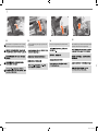
3:4
Attach a foot to each leg, using four screws in each foot.
First t all four screws loosely, then tighten them up.
각 발에 나사 네 개씩 사용하여 각 다리에 발을 연결합니다.
먼저 나사 네 개를 모두 느슨하게 맞춘 후 꽉 조이십시오.
为每个支柱连接底板,每个底板使用四枚 螺钉。先松松地
拧上这四枚螺钉,然后 再拧紧。
為每隻腳架裝上腳座,每個腳座各用四顆螺絲鎖 定。先將
四顆螺絲大致裝上,然後再一一鎖緊。
4本のネジで各足部を各脚部に固定します。まず4本すべて
のネジを緩めに取り付けてから、固く締めます。
3:5
Turn the stand upright.
스탠드를 똑바로 세웁니다.
将底座立起来。
7 把機架倒過來正放。
スタンドを垂直に立てます。
4:1
Check that all the stand screws are tight. If you can’t
tighten all the screws properly, try unscrewing one or
two so that the legs, feet and cross braces are properly
aligned, and then retighten them.
4:2
Put the stand assembly onto the printer. Peel open the
protective cover and then place the stand onto the printer.
Looking at the front of the printer, rst place the leg marked
in green on the right-hand side.
3 4 Attach the Stand to the printer / /
/ /
프린터 앞면을 살펴 보면서 먼저 오른쪽 면에
녹색으로 표시된 곳에 다리를 둡니다.
以打印机正面为
参照,首先将标为绿色的支架放在右侧。
請面對印表機
的正面,首先將標記為綠色的支架置放在右手邊。
プリン
タの前面を見て、緑色の印が付いている脚を右側に取
り付けます。
ap.indd 5 9/30/2010 4:09:02 PM

4
X4
EN
KO
ZHCN
ZHTW
JP
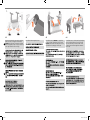
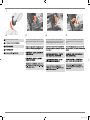
4:5
Tilt and lift the printer (1): WARNING: 2–3 people for the
E+/A0+-size model; 2 people for the D/A1-size model.
CAUTION: Ensure the area in front of the printer is clear of
any obstacles such as packaging or rolls of paper.
4:6
Tilt and lift the printer (2): Tilt the printer through 90-degrees
onto its side, and then stand it up on its legs. The printer
may seem a little wobbly on one side, but that is correct
provided the screws have been tightened as indicated in
previous steps.
x3
4:3
Secure the stand with the four screws that have large at
heads. Two screws (on one leg) are secured normally.
CAUTION: Two of the screws on the same leg will appear
to be not fully tightened, as they will not go in as far as the
others—they should be rm but not over tight.
4:4
Ensure all four brakes are applied, as shown.
ap.indd 6 9/30/2010 4:09:03 PM

4
X2
EN
KO
ZHCN
ZHTW
JP
5:1
Lay out the components of the basket.
取出纸筐的组件
바스켓의 부품들을 바닥에 진열합니다.
將承紙籃的組件擺放整齊。
バスケットの部品を並べます
4:7
Remove the plastic covering and foam end caps.
4:8
Remove the tapes from the window and the spindle. Remove
also the small bag of desiccant material.
4:9
Remove the tapes from the spindle at the back of the printer.
5 Assemble the paper Bin
ap.indd 7 9/30/2010 4:09:04 PM

EN
KO
ZHCN
ZHTW
JP
5:4
Attach the basket’s front tube to the two short tubes on each
foot.
将纸筐的前管连接到每个底板的两根短
管上。
바스켓의 앞쪽 튜브를 각 발의 작은 튜브 두 개에
연결합니다.
將承紙籃的前端管條連接到兩根個別裝在各腳座
上的短管條。
バスケットの前面のチューブを各足部の2本の
短いチューブに取り付けます。
5:5
Rest the basket’s rear tube on the supports that you have just
tted to each leg of the stand.
将纸筐的后管放在已经安装到每个底座支 柱的支架上
스탠드의 각 다리에 맞추었던 지지대에 바스켓의
뒤쪽 튜브를 맞춥니다.
將承紙籃的後端管條擱放在剛才安插到機架各隻腳
架上的支托。
スタンドの各脚部に取り付けたバスケットサポー
トに、バスケットの背面のチューブを乗せます
5:2
Fit the basket supports to the stand legs, one to each leg.
将纸筐支架安装到底座支柱上,每个支 柱 安装一个支架。
바스켓 지지대를 스탠드의 각 다리마다 하나씩
맞춥니다.
將承紙籃支托安插到機架的腳架,每隻腳架各有
一個。
スタンドの各脚部に、バスケットサポートを 1つずつ取
り付けます。
5:3
Fit the two short tubes to the printer’s feet, one on the front
of each foot. Each tube should click into place.
将两个短管安装到打印机底板上,每个底
板前面安装一个短管。两个短管都应该卡
入到位。
작은 튜브 두 개를 프린터 앞쪽 발에 각각 하나씩
맞추십시오. 각 튜브가 딸깍 소리를 내야 합니다.
將兩根短的管條安裝到印表機的腳座上,每根管
條都應該喀嚓一聲卡入定位。
2本の短いチューブをプリンタの各足部の前面に
合わせます。各チューブを所定の位置にカチッと
音がするまで押し込みます。
5 / / / /
ap.indd 8 9/30/2010 4:09:04 PM

EN
KO
ZHCN
ZHTW
JP
5:6
The basket is now complete.
纸筐现已安装完毕 。
바스켓이 이제 완성되었습니다.
承紙籃就完成了。
これでバスケットの取り付けは完了です。
WARNINGS
• When the printer is powered on, keep objects such as
hair, jewelry and clothing away from the printer mecha-
nisms.
• Make sure that the power cord supplied with your
printer matches your AC power outlet connection. Only
use a three-wire (earth-grounded) power cord with this
printer.
6:4
Introductory information is also In the “Installation pack”
of documentation and other items. It contains important
information for the use of the printer.
6 Introductory information / 기본 정보
/ 介绍性信息 / 資訊導引 / 基本情報
7 Switch On and Choose a Language / /
/ /
5
7:1
Plug the power cord into the socket at the back of the
printer and then into the AC power outlet.
ap.indd 9 9/30/2010 4:09:06 PM

EN
KO
ZHCN
ZHTW
JP
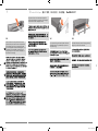
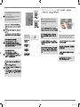
8:2
Insert the ink cartridges into their correct positions. Colored
labels on the ink cartridges must correspond with the same
colored labels on the printer.
7:2
Switch on if the printer doesn’t automatically come on: The
p On/Off switch is located on the front left of the printer.
It is a simple pushbutton switch with a green light (LED) to
indicate when it is On. Switch the power on by pressing
the button once. If there is no sound from the printer and no
light on the switch’s LED, you have a power problem. Check
the power cord connections and power source.
7:3
Select a language: After up to a minute, the printer’s front-
panel menu will invite you to set the language. The menus
are available in the following languages: English, Italian,
Portuguese, German, French, Spanish, Catalan, Japanese,
Korean, Traditional Chinese, and Simplied Chinese. On
the front panel, press the or key until the language
you want is highlighted. Then press the Enter key to select
the language.
7 8 Insert Ink Cartridges / / /
/
8:1
Open the ink cartridge cover and remove the packaging
from the ink cartridges, which are in the “Installation pack”
of documentation and other items.
ap.indd 10 9/30/2010 4:09:07 PM

EN
KO
ZHCN
ZHTW
JP
8 9 Replace Set-Up Printheads with Active Printheads / /
/ /
9:1
When you are prompted to do so in the front panel, open
the window and locate the carriage assembly. This will be
accessible once the ink tubes and set-up printheads have
lled with ink.
8:3
Close the ink cartridge cover. The printer starts to initialize
its ink system as soon as the last cartridge is inserted.
Wait for about a minute until this has nished.
The set-up printheads are provided to protect the ink system while the printer is being transported from the factory, and to ll
up the ink tubes inside the printer when it is rst initialized. They must be replaced by active (normal) printheads when the
printer’s tubes have lled with ink. Set-up printheads cannot be used for printing. It is important not to remove the set-up print-
heads too early, as they are required while the printer is being initialized. When you have removed the set-up printheads (as
described in this stage), you should throw them away, as they cannot be used for printing and are not needed any more.
ap.indd 11 9/30/2010 4:09:07 PM

EN
KO
ZHCN
ZHTW
JP
9:5
With controlled force pull the blue handle upwards until the
printhead is released from the carriage assembly.
9
9:4
To remove a set-up printhead, lift up the blue handle.
9:3
Lift up the printhead cover; this will give you access to the
set-up printheads.
9:2
Release the latch on the printhead cover. You may need to
hold this latch up out of the way during the next steps.
ap.indd 12 9/30/2010 4:09:08 PM

EN
KO
ZHCN
ZHTW
JP
9:9
Close the latch on the printhead cover. The latch may feel
rather stiff, but don’t worry as it needs some pressure to
close it.
9
9:8
When you have replaced all the set-up printheads with
normal printheads, pull the printhead cover down over the
printheads, ensuring that the cover hooks over the latch.
9:7
Insert a new normal printhead ensuring that the colored
label on the printhead corresponds to that on the printhead
slot.
9:6
Remove the tape from the new printheads.
ap.indd 13 9/30/2010 4:09:09 PM

EN
KO
ZHCN
ZHTW
JP
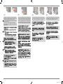
10:2
At the back of the printer, remove the empty spindle by
pulling rmly on each end as indicated.
9 10 Load a Roll of Paper / / / /
10:1
If your printer has legs, make sure the printer wheels are
locked (the brake lever is pressed down) to prevent the
printer from moving.
The printer will now use a certain amount of paper for
checking and calibration. (If you prefer to use sheet paper,
see the Pocket Guide for loading instructions.)
9:10
Close the window. After the replacement of the set-up
printheads, the printer checks that the normal printheads
are functioning correctly. This may take several minutes.
You will be prompted to accept Printhead Alignment— cor-
rect alignment of the printheads is essential for good-
quality printing. For this you will need to load paper, as
described in the next stages.
ap.indd 14 9/30/2010 4:09:09 PM

EN
KO
ZHCN
ZHTW
JP
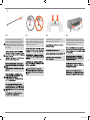
10:6
With the blue-colored roll stop on the right (as seen from
the back of the printer), slide the spindle into the printer left
and then right as shown by the arrows. The paper should
oriented on the roll exactly as shown.
10
10:5
Put the removable stop on to the upper end of the
spindle, and push it down as far as it will go.
10:3
The spindle has a stop at each end to keep the roll in
position. The stop that is colored blue can be removed to
mount a new roll; it slides along the spindle to hold rolls
of different widths. Remove the blue-colored stop from the
spindle end, and stand the spindle vertically, with the xed
stop on the oor.
10:4
Slide the new roll of paper on to the spindle. Make sure the
orientation of the paper is loaded exactly as shown. If it is
not, remove the roll, turn it through 180 degrees vertically
and slide it back on to the spindle.
ap.indd 15 9/30/2010 4:09:10 PM

EN
KO
ZHCN
ZHTW
JP
10:10
Follow the prompts (see steps 11 to 13). Try to avoid
touching the paper in the middle (keep your ngers as close
as possible to each edge). Handle glossy paper by the
edges or wear cotton gloves. Skin oils can interact with the
ink and cause it to smear.
10
10:7
A front-panel message prompts you to load paper to align
the printheads. Press the Enter key.Then, as above left, select
Load roll (or Load sheet, if you prefer–see the Pocket Guide
for loading instructions) and press Enter. Using the or
keys, select the type of paper loaded (see above right) and
press the Enter key. (If in doubt, you should nd the ‘type’ of
the paper on its box.)
10:9
From the front of the printer lean over the top and feed the
paper towards you into the slot at the back of the printer,
as shown here. (You may nd it easier if the paper bin is
pushed back out of the way.)
10:8
Lift the blue paper-load lever.
ap.indd 16 9/30/2010 4:09:11 PM

EN
KO
ZHCN
ZHTW
JP
10:12
At the front of the printer, align the paper against the blue
line as shown here.
10:14
If there is an excess of loose paper wrap it back onto the
roll by turning the roll; then press Enter.
10:11
Leaning over the printer, feed the paper through towards
the front.
10:13
Lower the blue paper-load lever. The printer checks the
alignment of the paper. If it is not correctly aligned, the front
panel displays help instructions. The printer trims the edge
of the roll.
10
ap.indd 17 9/30/2010 4:09:12 PM

EN
KO
ZHCN
ZHTW
JP
10:15
The printer will now print its alignment pattern, using the paper you have loaded. If there is a problem print-
ing, check the front panel error messages. Explanations of these messages are in the Pocket Guide.
You should not cancel the alignment print as correct alignment of the printheads is essential for good-quality
printing. You may also be prompted to let the printer perform its Color Calibration routine. Again, don’t
cancel this as it will help ensure that the colors printed are best for the paper you have loaded. Printhead
Alignment and Color Calibration are different processes and should both be done when required. They are
briey described in the Pocket Guide and more fully in the online User’s Reference Guide.
If you have purchased a network card, for connecting your printer to a local area network (LAN), now is
a good time to install it—see Stage 12. Also install now any HP-GL/2 Accessory card and any additional
memory for your Accessory card. See the instructions packaged with these items for full information on how
to install them. The HPL/2 Accessory card is installed in much the same way as a LAN card, as in Stage 12.
See Stage 12 for connecting a LAN cable.
10 11 Understand Printer Connections / /
/ /
ap.indd 18 9/30/2010 4:09:13 PM

EN
KO
ZHCN
ZHTW
JP
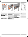
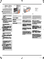
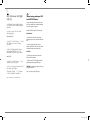
Sockets for connecting your printer to a computer or to a
network. The diagram on the right shows the sockets (or
“ports”) that you can use.
• The USB and parallel sockets are at the back of the
printer, alongside the mains socket.
• The LAN cable socket is inside the back cover of the
printer—see Stage 12 on for how to access it.
NOTE: An internal HP JetDirect Print Server may
already be installed in your printer, inside the
compartment at the top left rear of the printer. If it
is, skip to step 8.
12 Install and Connect a LAN Card / /
/ /
11
12:1
Before installing a card, switch off the printer and
unplug it from the mains electricity supply.
USB socket
Parallel socket
LAN cable socket
(inside back cover)
ap.indd 19 9/30/2010 4:09:14 PM

EN
KO
ZHCN
ZHTW
JP
12
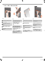
12:5
When you have inserted the card, screw it into place, using
its two screws (at the top and bottom of the card). Again,
this can be done with a screwdriver or manually.
12:4
To insert a LAN card (or an Accessory card), remove the
metal cover from the appropriate slot by unscrewing its two
screws. You can use a screwdriver or do it manually.
12:2
Carefully remove the plastic cover from the left-hand back
of the printer by unclipping it. This cover gives access to the
two slots for an Accessory card and a LAN card.
a. Press in the thumb-tab on the side furthest from the edge
that has the cable-hole.
b. Ease the cover out in the direction of the embossed
arrow, pivoting it by the hinge clips on the side that has the
edge cable-hole.
12:3
Remove the cover completely. Inside the compartment there
are two slots for a LAN card or an Accessory card. You can
use either slot for either card, but we recommend putting a
LAN card on the left (nearer to the front of the printer) and
an Accessory card on the right. In this way the cable from
the LAN card can easily pass through the slot in the door.
ap.indd 20 9/30/2010 4:09:15 PM
ページが読み込まれています...
ページが読み込まれています...
ページが読み込まれています...
ページが読み込まれています...
-
 1
1
-
 2
2
-
 3
3
-
 4
4
-
 5
5
-
 6
6
-
 7
7
-
 8
8
-
 9
9
-
 10
10
-
 11
11
-
 12
12
-
 13
13
-
 14
14
-
 15
15
-
 16
16
-
 17
17
-
 18
18
-
 19
19
-
 20
20
-
 21
21
-
 22
22
-
 23
23
-
 24
24


HP DesignJet 510 Printer series Assembly Instructions
- カテゴリー
- 印刷
- タイプ
- Assembly Instructions
他の言語で
- English: HP DesignJet 510 Printer series
関連論文
-
HP Ink Tank 118 ユーザーガイド
-
-
HP Ink Tank 316 ユーザーガイド
-
-
-
-
-
-
HP DesignJet 820 MFP series リファレンスガイド
-