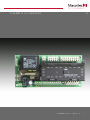
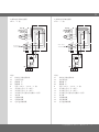
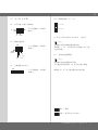
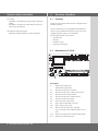
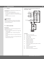
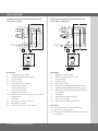
Marantec AS 210B は、有線又は無線の安全停止、手動、自動で動作する電動ドアを制御する装置です。本体は、約1.8kgで、設置に必要な寸法は、幅 16.7cm、高さ 19.0cm、奥行き 8.5cm です。230V または 400V の電源で動作します。 最大消費電力は 2200W - 3.2A で、最長動作時間は 120 秒です。 停電時に非常用操作機能を使用できます。 AS 210B の他の機能には、赤色信号灯、照明灯制御、自動下降、動作時間監視があります。 挿入型モジュール ZM SKS B と組み合わせると、機能を拡張することができます。
Marantec AS 210B は、有線又は無線の安全停止、手動、自動で動作する電動ドアを制御する装置です。本体は、約1.8kgで、設置に必要な寸法は、幅 16.7cm、高さ 19.0cm、奥行き 8.5cm です。230V または 400V の電源で動作します。 最大消費電力は 2200W - 3.2A で、最長動作時間は 120 秒です。 停電時に非常用操作機能を使用できます。 AS 210B の他の機能には、赤色信号灯、照明灯制御、自動下降、動作時間監視があります。 挿入型モジュール ZM SKS B と組み合わせると、機能を拡張することができます。


-
 1
1
-
 2
2
-
 3
3
-
 4
4
-
 5
5
-
 6
6
-
 7
7
-
 8
8
-
 9
9
-
 10
10
-
 11
11
-
 12
12
-
 13
13
-
 14
14
-
 15
15
-
 16
16
-
 17
17
-
 18
18
-
 19
19
-
 20
20
-
 21
21
-
 22
22
-
 23
23
-
 24
24


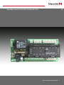
Marantec AS 210B は、有線又は無線の安全停止、手動、自動で動作する電動ドアを制御する装置です。本体は、約1.8kgで、設置に必要な寸法は、幅 16.7cm、高さ 19.0cm、奥行き 8.5cm です。230V または 400V の電源で動作します。 最大消費電力は 2200W - 3.2A で、最長動作時間は 120 秒です。 停電時に非常用操作機能を使用できます。 AS 210B の他の機能には、赤色信号灯、照明灯制御、自動下降、動作時間監視があります。 挿入型モジュール ZM SKS B と組み合わせると、機能を拡張することができます。
他の言語で
- English: Marantec AS 210B Owner's manual