
CN
扩展卡 ZM-SKS B使用说明书
CN
扩展卡ZM-SKS B / 版本A 1.3 – 1

2 – 扩展卡ZM-SKS B / 版本A 1.3
1. 概述 3. 一般安全提示
2. 符号说明
操作说明书原件
– 受版权保护。
– 翻印或摘录均需获得许可。
– 保留改进技术的权利。
– 所有尺寸均以毫米为单位。
– 图示未按正确比例绘制。
保证
只有注意了使用说明书中的警告和安全提示,我们
才对产品功能和安全性提供保证。
如果因为没有注意警告和安全提示而导致人员受伤
或物体损坏,我们 Marantec 驱动器有限公司不负
责任。
规范使用
ZM-SKS B 是控制器AS 210 B的扩展卡。它是专为大
门控制器而设计的。
只允许在干燥的房间内使用。
目标群体
只有经过培训的、具有资格的电工可以连接控制
器、对控制器进行编程和维护。
经过培训的、具有资格的电工必须满足如下要求:
- 了解一般的以及特殊的安全和事故预防法规;
- 了解重要的电工法规;
- 受过安全装备使用和维护方面的培训;
- 能够识别与电相关的危险。
安装和连接提示
- 进行与电相关的作业之前必须将设备与电源断
开。 作业过程中必须确保电源一直保持断开。
- 必须遵守当地的安全保护规定。
- 电网和控制导线必须分开铺设。
致人受伤危险!
务必遵守安全提示!
致物损坏危险!
务必遵守安全提示!
信息
特殊提示
或
指示其它信息源
1. 概述 2
2. 符号说明 2
3. 一般安全提示 2
4. 产品概览 3
5. 启动 4
6. 欧盟符合性声明 7

CN
扩展卡ZM-SKS B / 版本A 1.3 – 3
检验标准和法规
连接、编程和维护的时候必须遵守以下法规(这里
所列未必完全)。
建筑产品标准
- EN 13241-1(不具有防火防烟性质的产品)
- EN 12445(动力操作大门的使用安全 -
检查方法)
- EN 12453(动力操作大门的使用安全 - 要求)
- EN 12978 (动力操作大门的保护装置 - 要求和
检查方法)
EMV
- EN 55014-1(家用电器干扰排放)
- EN 61000-3-2 (对供电网络的扰动 – 谐波)
- EN 61000-3-3 (对供电网络的扰动 –
电压波动)
- EN 61000-6-2(电磁兼容性 (EMV) -
第 6-2 部分: 通用标准 – 抗干扰性 -
工业区)
- EN 61000-6-3(电磁兼容性 (EMV) -
第 6-3 部分: 通用标准 – 干扰排放 -
住宅区,办公区和商业区以及小公司)
机械指令
- EN 60204-1 (机械安全性,机械电力装备;
第 1 部分: 一般要求)
- EN 12100-1 (机械安全性 - 基本概念,一般设
计原则;第 1 部分: 基本术语,方法论)
低电压
- EN 60335-1 (房屋用或类似用途的电气设备的
安全)
- EN 60335-2-103(对大门、门、窗驱动器的特殊
要求)
工作场所委员会(ASTA)
- ASR A1.7(工作场所“门与大门”技术规则)
4.1 功能
扩展卡 ZM SKS B 通过 DIP 开关提供以下功能:
- 对 OPTO电子安全触板进行分析
- 对 8.2 千欧姆安全触板进行分析
- 对气动安全触板进行测试
- 自动关门
- 大院照明灯或红色警示灯功能
- 120 秒运行时间监控
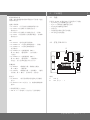
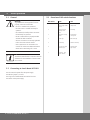
4.2 扩展卡ZM-SKS B
说明:
A: LED 灯
B: DIP 开关 1 – 7
4. 产品概览
A
B

4 – 扩展卡ZM-SKS B / 版本A 1.3
5. 启动
5.1 一般说明
警告!
为了保证顺利运行,必须注意以下几
点:
- 大门已安装好,并且准备就绪。
- 驱动电机已安装好,并且已准备就
绪。
- 控制设备和安全设备已安装好,并
且已准备就绪。
- 按规定安装并连接控制器AS 210
B。
- 拧紧控制器和电机侧的所有电机连
接。
- 与控制器连接的所有组件需要至少
一个额定电压> 230伏的附加绝缘
件。
信息:
安装大门控制器 AS 210 B 时请参阅
相关指导手册。
5.2 安装到主板 AS 210 B 上
切断设备的电源。
拆下跳线 1、2 和 5。
将主板 ZM-SKS B B 插入插线板 X7 中。
接通电源。
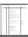
5.3 DIP 开关功能一览表
DIP 开关 开 关
1 8.2 千欧姆安
全触板
OPTO 安全触板
2 激活压力波测
试
无测试功能
3 自动关门 无自动关门
4
大院照明灯 红灯
5 延迟 无延迟
6 连续信号
(警示灯)
闪烁信号
(警示灯)
7 学习打开保持
时间
-

CN
扩展卡ZM-SKS B / 版本A 1.3 – 5
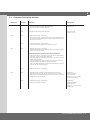
5.4 DIP 开关功能一览表
DIP 开关 位置 功能 连接
DIP 开关 1 开 - 对 8.2 千欧姆安全触板系统进行分析
- 对连有一个 8.2 千欧姆电阻的气动安全触板系统进行评估
接线板 X3、
端子 7 + 8
关 对 OPTO 安全触板系统进行分析。 接线板 X3、
端子 7 + 8 + 9
DIP 开关 2 开 - 启动压力波测试。
- 在关门极限位置上进行压力开关测试。
因此在安装大门时必须暂时断开压力波触点。
-
关 - 不启动压力波测试。
- 关门极限位置上不进行压力波开关测试。
-
DIP 开关 3 开 - 启动自动关门功能。
- 在预设的打开保持时间结束后从开门极限位置自动关闭大门。
自动关门激活时的基本功能
- 如果大门关闭期间,通道光栅被中断,则大门暂停,然后重新
打开,打开保持时间重新计时。
- 如果在打开保持时间内通道光栅被中断,则打开保持时间重新
计时。
- 如果大门关闭期间操作安全触板,则大门暂停,然后重新打
开,打开保持时间重新计时。
如果在一个周期内 3 次操作了安全触板,则大门无法再自动关
闭。
-
关 - 关闭自动关门功能。 -
Dipp 4 开 - 通过开门命令打开大院照明灯功能。
- 大院照明灯灯光的持续时间默认设置为 2 分钟。可通过 DIP
开关 5 设置延迟时间,即驱动装置在灯光亮起 3 秒后才开始
运行。
无电位开关触点 K3,
端子排 X9,
端子 1 + 2 用于打开 一个
外部 光源。
关 - 开启红色警示灯功能。
- 通过 DIP 开关 5 可以在 2 个选项间进行选择。
无电位开关触点 K3,
端子排 X9,
端子 1 + 2 用于打开 一个
红色警示灯。
DIP 开关 5 开 带延迟功能的红色警示灯
(与 DIP 开关 4 的关闭功能有关)
- 自动关门时预警点亮或闪烁 3 秒(DIP 开关 6)。
- 每次运行时预警点亮或闪烁 3 秒(DIP 开关 6)。
- 在运行期间点亮或闪烁 3 秒(DIP 开关 6)。
- 在大门关闭时有 5 秒的余光持续时间
(点亮或闪烁/DIP 开关 6)。
-
关 无延迟功能的红色警示灯
(与 DIP 开关 4 的关闭功能有关)
- 自动关门时预警点亮或闪烁 3 秒(DIP 开关 6)。
- 运行期间点亮或闪烁 3 秒(DIP 开关 6)。
-
DIP 开关 6 开 - 连续信号 – 红色警示灯功能下警示灯在大门运行和预警期间
持续点亮。
-
关 - 闪烁信号 – 红色警示灯功能下警示灯在大门运行和预警期间
闪烁。
-

6 – 扩展卡ZM-SKS B / 版本A 1.3
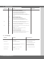
5. 启动
DIP 开关 位置 功能 连接
DIP 开关 7 开 学习打开保持时间。打开保持时间均包括 3 秒的预警时间在内。
例如:如果要将打开保持时间设为 20 秒,
1. 大门向开门位置移动。
2. 关闭电源。
3. 通过 DIP 开关 3 打开自动关门功能。
4. 接通电源。
5. 打开DIP 开关 7(LED 闪烁),20秒后再次关闭。
6. 打开保持时间被设置为 20 秒。
-
5.5 LED 提示信息
LED 灯 含义 解决方法
LED 闪烁 1 次 安全触板被操作/受到干扰 检查安全触板,如需要,清除大门移动路径上
的障碍物
LED 闪烁 2 次 通道光栅被中断 检查光栅,如需要,清除大门移动路径上的障
碍物
LED 闪烁 3 次 压力波测试结果为负,大门只能在松开即停
(Deadman)功能下向关门方向移动
在松开即停(Deadman)功能下关闭大门。获得
正的压力波测试结果后,说明故障已排除。
LED 闪烁 4 次 运行时间超过 120 秒。 重复开门或关门命令。
LED 快速闪烁 打开保持时间结束 -

CN
扩展卡ZM-SKS B / 版本A 1.3 – 7
我们特此声明,以下产品:
扩展卡ZM-SKS B
符合机械指令 (2006/42/EG) 的基本要求:
此外,非独立式机械装置还符合欧盟建筑产品指令
(89/106/EWG)、欧盟电磁兼容性指令(2004/108/
EG)和欧盟低电压指令(2006/95/EG)的所有规
定。
使用了以下标准:
EN 60204-1
机械安全,机器的电气设备;第1部分:一般要求
EN 12100-1
机械安全 -基本概念,一般设计原则-第1部分:基
本术语,方法
DIN EN 12453
动力门的使用安全-要求
DIN EN 12604
大门-机械性能-要求
EN 61000-6-2
电磁兼容性(EMV)-第6-2部分:-通用标准-工
业环境抗扰度
EN 61000-6-3
电磁兼容性(EMV)-第6-3部分:
通用标准-居住、商业和轻工业环境用辐射标准
EN 60335-1
家用和类似用途电器的安全标准
EN 60335-2-103
对大门、房门和窗户驱动装置的特殊要求
生产商和文档管理方
Marantec GmbH & Co. KG, Remser Brook 11,
D-33428 Marienfeld
根据EG-机械指令 2006/42/EG 中附录 VII,B部分
的规定创建专门的技术文件档案。我们有义务遵照
合理要求在适当期限内将该文档的电子版本提交给
市场监管部门。
只有当已确认,安有非独立式机械装置的设备符合
机械指令(2006/42/EG)的规定后,才可运行非独
立式机械装置。
地点,日期
Marienfeld,2011年10月10日
生产厂家签名
Klaus Goldstein
签字人职务
经理
6. 欧盟符合性声明


GB
Operating Instructions for Circuit Card ZM-SKS B
GB
Circuit Card ZM-SKS B / Rev.A 1.3 – 1

2 – Circuit Card ZM-SKS B / Rev.A 1.3
1. Contents 3. General safety instructions
2. Key to symbols
Original operating instructions
− Copyright.
− No part of these instructions may be reproduced without
our prior approval.
− Subject to alterations in the interest of technical progress.
− All dimensions given in mm.
− The diagrams in this manual are not to scale.
Guarantee
The function and safety of the equipment is only
guaranteed if the warning and safety instructions included in
these operating instructions are adhered to.
Marantec GmbH + Co.KG is not liable for any personal injury
or damage to property that occurs as a result of the warning
and safety instructions being disregarded.
Using the equipment for its intended purpose
The ZM-SKS B is an add-on module for the AS 210 B controls.
It is intended exclusively for controlling door systems.
Its use is only permitted in dry rooms.
Target group
Only qualied and trained electricians may connect,
programme and service the circuit card.
Qualied and trained electricians full the following
requirements:
− they have knowledge of the general and specic safety and
accident prevention regulations,
− they have knowledge of the relevant electrical regulations
− they are trained in the use and care of appropriate safety
equipment,
− they are capable of recognising the dangers associated
with electricity.
Instructions for installation and connection
− The controls must be disconnected from the electricity
supply before carrying out electrical works. It must be
ensured that the electricity supply remains disconnected
during the works.
− Local protective regulations must be complied with.
− Mains cables and control cables must be laid separately.
Danger of personal injury!
The safety instructions must be observed!
Warning! Danger to property!
The safety instructions must be observed!
Information
Special information
OR
Reference to other sources of
information
1. Contents 2
2. Key to symbols 2
3. General safety instructions 2
4. Overview of product 3
5. Initial operation 4
6. EC Declaration of Incorporation 7

GB
Circuit Card ZM-SKS B / Rev.A 1.3 – 3
Regulations and bases for testing
For connecting, programming and servicing, the following
regulations must be observed (the list is not exhaustive).
Construction product standards
− EN 13241-1 (Products without re resistance or smoke
control characteristics)
− EN 12445 (Safety in use of power operated doors -
Test methods)
− EN 12453 (Safety in use of power operated doors -
Requirements)
− EN 12978 (Safety devices for power operated doors and
gates - Requirements and test methods)
Electromagnetic compatibility
− EN 55014-1 (Radio disturbance, household appliances)
− EN 61000-3-2 (Disturbances in supply systems -
harmonic currents)
− EN 61000-3-3 (Disturbances in supply systems -
voltage uctuations)
− EN 61000-6-2 (Electromagnetic compatibility (EMC) -
Part 6-2: Generic standards - Immunity for industrial
environments)
− EN 61000-6-3 (Electromagnetic compatibility (EMC) -
Part 6-3: Generic standards - Emission standard for
residential, commercial and light- industrial environments)
Machinery guidelines
− EN 60204-1 (Safety of machinery, electrical equipment of
machines, part 1: general requirements)
− EN 12100-1 (Safety of machinery. Basic concepts, general
principles for design. Basic terminology, methodology)
Low voltage
− EN 60335-1 (Household and similar electrical appliances -
Safety)
− EN 60335-2-103 (Particular requirements for drives for
gates, doors and windows)
Committee for Workplaces (ASTA)
− Workplace regulation ASR A1.7 (“Doors and gates“)
4.1 Functions
The ZM SKS B circuit card offers the following
functions, which can be set via DIP switches:
− Evaluation for optoelectronic closing edge safety device
− Evaluation for 8.2 kOhm closing edge safety device
− Testing for pneumatic closing edge safety device
− Automatic closing timer
− Yard light or red trafc light function
− Excess travel monitoring, 120 seconds
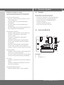
4.2 Circuit card ZM SKS B
Description:
A: LED
B: DIP switches 1 – 7
4. Overview of product
A
B

4 – Circuit Card ZM-SKS B / Rev.A 1.3
5. Initial operation
5.1 General
Warning!
To guarantee that the equipment functions
properly, it must be ensured that:
- the door is installed and operational.
- the drive motor is installed and ready for
operation.
- the command and safety devices are instal-
led and ready for operation.
- the AS 210 B controls are properly installed
and with all cables connected.
- all motor connections are securely tightened
both at the motor and the controls.
- each component to be connected to the
controls has at least one additional isolation
device with a rated voltage of > 230 V.
Information:
The relevant manufacturer’s instructions must be
adhered to for the installation of the AS 210 B
door controls.
5.2 Connecting to circuit board AS 210 B
Disconnect the system from the power supply.
Remove jumpers 1, 2 and 5.
Plug circuit card ZM-SKS B into terminal block X7.
Switch on the power supply.
5.3 Overview of DIP switch functions
DIP switch ON OFF
1 8,2 kOhm
closing edge safety
device
OPTO closing edge
safety device
2 Pressure switch
testing activa-
ted
No testing
3 Automatic closing
timer
No automatic
closing timer
4
Yard light Red trafc light
5 Time delay Without time delay
6 Continuous signal
(trafc light)
Flashing trafc
(light signal)
7 Learning - door
open duration
-

GB
Circuit Card ZM-SKS B / Rev.A 1.3 – 5
5.4 Overview of DIP switch functions
DIP switch Setting Function Connection
DIP 1 ON - Evaluation for 8.2 KOhm closing edge safety device
- Evaluation for pneumatic closing edge safety devices,
in connection with an 8.2 KOhm resistance
Terminal block X3,
Terminals 7 + 8
OFF Evaluation for OPTO closing edge safety device. Terminal block X3,
Terminals 7 + 8 + 9
DIP 2 ON - Pressure switch testing is switched on.
- Pressure switch testing is carried out with the door at the CLOSED end positi-
on. For this, the pressure switch contact must be broken for a moment as the
door touches the ground.
-
OFF - Pressure switch testing is not switched on.
- The pressure switch is not tested at the CLOSED end position.
-
DIP 3 ON - Automatic closing timer is switched on.
- From the OPEN end position, the door closes automatically after the program-
med door-open duration expires.
Basic functions when automatic closing timer is switched on
- If the photocell barrier is interrupted during closing, the door stops and then
opens again. The door open duration starts anew.
- If the photocell barrier is interrupted during the door open duration, the door
open duration starts anew.
- If the closing edge safety system is activated during closing, the door stops
and then opens again. The door open duration starts anew.
If the closing edge safety device is activated three times during one cycle, the
door does not close automatically again.
-
OFF - Automatic closing timer is switched off. -
DIP 4 ON
- Yard light function is switched on when the OPEN command is given.
- With the yard light setting, the light then stays on for 2 minutes. Via DIP
switch 5 it can be set to delay, which means that the drive does not start until
the light has been on for 3 seconds.
Potential-free
switching contact K3,
terminal block X9,
terminals 1 + 2 for connecting
an external light source.
OFF - Red trafc light function is switched on.
- 2 options are available using DIP 5.
Potential-free
switching contact K3,
terminal block X9,
terminals 1 + 2 for connecting a
red trafc light.

6 – Circuit Card ZM-SKS B / Rev.A 1.3
5. Initial operation
DIP switch Setting Function Connection
DIP 5 ON Red trafc light with delay
(relates to the functions of DIP 4, OFF)
- Light shines continuously or ashes (DIP 6) to give advance
warning of automatic closing 3 seconds beforehand.
- Light shines continuously or ashes (DIP 6) to give advance
warning 3 seconds before every door movement.
- Light shines continuously or ashes during door movement (DIP 6).
- Signal (continuous or ashing / DIP 6) continues for 5 seconds after door has
closed.
-
OFF Red trafc light without delay
(relates to the functions of DIP 4, OFF)
- Light shines continuously or ashes (DIP 6) to give advance
warning of automatic closing 3 seconds beforehand.
- Light shines continuously or ashes during door movement (DIP 6).
-
DIP 6 ON - Continuous signal – for the red trafc light function the light remains on
continuously during door movements and warning periods.
-
OFF
- Flashing signal – for the red trafc light function, the trafc light ashes
during door movements and warning periods.
-
DIP 7 ON „Learning“ the door open duration. The door open duration always includes a
warning time of 3 seconds.
Example: The door is required to stay open for 20 seconds:
1. Drive the door to the OPEN position.
2. Switch off the mains power supply.
3. Switch on the automatic closing timer using DIP switch 3.
4. Switch on the mains power supply.
5. Switch on DIP switch 7 (LED ashes); switch off again after 20 seconds.
6. The open door duration is now programmed to 20 seconds.
-
5.5 LED messages
LED signal Meaning Remedial measures
LED ashes once Closing edge safety device activated /
malfunctioning
Check the closing edge safety device,
remove any obstacles from path of door
LED ashes twice Photocell barrier is interrupted Check the photocell barrier,
remove any obstacles from path of door
LED ashes three times Pressure switch testing is negative, now the door can be
closed in deadman mode only
Close the door in deadman mode.
After a positive pressure switch test,
the malfunction has been remedied
LED ashes four times A running time of 120 seconds has been
exceeded
Give a new OPEN or CLOSE command
LED ashes quickly Door open duration is expiring

GB
Circuit Card ZM-SKS B / Rev.A 1.3 – 7
6. EC Declaration of Incorporation
We hereby declare that the product described below:
Circuit Card ZM-SKS B
is in conformity with all essential requirements of the
Machinery Directive 2006/42/EC.
In addition the partly completed machinery is in conformity
with the Construction Products Directive 89/106/EC, the
Electromagnetic Compatibility Directive 2004/108/EC and the
Low Voltage Directive 2006/95/EC.
The following standards were applied:
EN 60204-1
(Safety of machinery, electrical equipment of machines; Part 1:
General requirements)
EN 12100-1
(Safety of machinery - Basic concepts, general principles for
design - Part 1: Basic terminology, methodology)
DIN EN 12453
(Safety in use of power operated doors - Requirements)
DIN EN 12604
Doors and gates. Mechanical aspects. Requirements
EN 61000-6-2
(Electromagnetic compatibility (EMC) - Part 6-2:
Generic standards - Immunity for industrial environments)
EN 61000-6-3
Electromagnetic compatibility (EMC) - Part 6-3:
Generic standards - Emission - standard for residential,
commercial and light-industrial environments)
EN 60335-1
(Household and similar electrical appliances - Safety)
EN 60335-2-103
(Particular requirements for drives for gates, doors and
windows)
Manufacturer and manager of documentation
Marantec GmbH & Co., Remser Brook 11,
D-33428 Marienfeld
The relevant technical documentation is compiled in accord-
ance with Annex VII (B) of the Machinery Directive 2006/42/
EC. We undertake to transmit, in response to a reasoned
request by the market surveillance authorities, this informa-
tion in electronic form within a reasonable term.
The machinery is incomplete and must not be put into
service until the machinery into which it is to be incorporated
has been declared in conformity with the provisions of the
Machinery Directive 2006/42/EC.
Place / Date:
Marienfeld, 10/10/2011
Manufacturer’s signature:
Klaus Goldstein
Position of signatory:
Management

#1700009318
#97348
-
 1
1
-
 2
2
-
 3
3
-
 4
4
-
 5
5
-
 6
6
-
 7
7
-
 8
8
-
 9
9
-
 10
10
-
 11
11
-
 12
12
-
 13
13
-
 14
14
-
 15
15
-
 16
16


