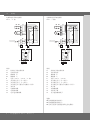
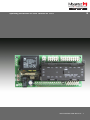
Marantec AS 210B は、安全にドアのシステムを制御したいと望む人々にとって理想的なソリューションです。この製品は、ドアの誤動作や事故を防ぐよう設計されており、頑丈な構造と信頼性の高い性能を備えています。AS 210B は、さまざまな安全機能を搭載しており、ドアの開閉中の事故を防ぐのに役立ちます。これらの機能には、閉鎖エッジ安全デバイスストリップ、過剰移動監視、および自動閉鎖が含まれます。また、赤信号とヤードライトを制御することもできます。AS 210B は、さまざまなドアシステムに簡単に設置でき、さまざまなアクセス制御システムと互換性があります。AS 210B を使用することで、ドアの安全性とセキュリティを向上させ、安心してドアのシステムを使用することができます。
Marantec AS 210B は、安全にドアのシステムを制御したいと望む人々にとって理想的なソリューションです。この製品は、ドアの誤動作や事故を防ぐよう設計されており、頑丈な構造と信頼性の高い性能を備えています。AS 210B は、さまざまな安全機能を搭載しており、ドアの開閉中の事故を防ぐのに役立ちます。これらの機能には、閉鎖エッジ安全デバイスストリップ、過剰移動監視、および自動閉鎖が含まれます。また、赤信号とヤードライトを制御することもできます。AS 210B は、さまざまなドアシステムに簡単に設置でき、さまざまなアクセス制御システムと互換性があります。AS 210B を使用することで、ドアの安全性とセキュリティを向上させ、安心してドアのシステムを使用することができます。


-
 1
1
-
 2
2
-
 3
3
-
 4
4
-
 5
5
-
 6
6
-
 7
7
-
 8
8
-
 9
9
-
 10
10
-
 11
11
-
 12
12
-
 13
13
-
 14
14
-
 15
15
-
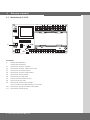 16
16
-
 17
17
-
 18
18
-
 19
19
-
 20
20
-
 21
21
-
 22
22
-
 23
23
-
 24
24


Marantec AS 210B は、安全にドアのシステムを制御したいと望む人々にとって理想的なソリューションです。この製品は、ドアの誤動作や事故を防ぐよう設計されており、頑丈な構造と信頼性の高い性能を備えています。AS 210B は、さまざまな安全機能を搭載しており、ドアの開閉中の事故を防ぐのに役立ちます。これらの機能には、閉鎖エッジ安全デバイスストリップ、過剰移動監視、および自動閉鎖が含まれます。また、赤信号とヤードライトを制御することもできます。AS 210B は、さまざまなドアシステムに簡単に設置でき、さまざまなアクセス制御システムと互換性があります。AS 210B を使用することで、ドアの安全性とセキュリティを向上させ、安心してドアのシステムを使用することができます。
他の言語で
- English: Marantec AS 210B Owner's manual
