Hitachi P 20SF Handling Instructions Manual
- カテゴリー
- パワーツール
- タイプ
- Handling Instructions Manual

Planer
P 20SF
English
Handling instructions
Keep for future reference

2

3

4

5

6

7

8

9

10
○
○

11

12
2
1
3
4
5
6
7
9A
10
17
1
4
5
6
7
9A
19
20
21
22
23
24
25
26
27
28
29
30
31
49
33
34
35
36
37
38
39
40
41
42
43
45
46
47
48
49
50
32
32
51
52
53
54
55
56
57
58
A
A
59
32
60
61
62
63
64
65
66
67
68
69
502 503 504
505
507
44

13

English
14
GENERAL POWER TOOL SAFETY WARNINGS
WARNING
Read all safety warnings and all instructions.
Failure to follow the warnings and instructions may result in electric shock, fi re and/or serious
injury.
Save all warnings and instructions for future reference.
The term “power tool” in the warnings refers to your mains-operated (corded) power tool or
battery-operated (cordless) power tool.
1) Work area safety
a) Keep work area clean and well lit.
Cluttered or dark areas invite accidents.
b) Do not operate power tools in explosive atmospheres, such as in the presence
of fl ammable liquids, gases or dust.
Power tools create sparks which may ignite the dust or fumes.
c) Keep children and bystanders away while operating a power tool.
Distractions can cause you to lose control.
2) Electrical safety
a) Power tool plugs must match the outlet.
Never modify the plug in any way.
CONTENTS
GENERAL POWER TOOL SAFETY WARNINGS ........................................14
PLANER SAFETY WARNINGS ....................................................................17
SYMBOL .......................................................................................................17
SPECIFICATIONS ........................................................................................ 17
STANDARD ACCESSORIES .......................................................................17
OPTIONAL ACCESSORIES (sold separately)..............................................18
APPLICATIONS ............................................................................................18
PRIOR TO OPERATION ...............................................................................18
PLANING PROCEDURES ............................................................................18
CARBIDE BLADE ASSEMBLY AND DISASSEMBLY AND ADJUSTMENT
OF CUTTER BLADE HEIGHT (FOR DOUBLE EDGED BLADE TYPE) ........20
BLADE ASSEMBLY AND DISASSEMBLY AND ADJUSTMENT OF
BLADE HEIGHT (FOR RESHARPENABLE BLADE TYPE) ..........................22
SHARPENING THE RESHARPENABLE BLADES .......................................23
ATTACHING AND DETACHING THE DUST ADAPTER
(OPTIONAL ACCESSORY) ..........................................................................23
MAINTENANCE AND INSPECTION ............................................................24
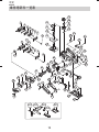
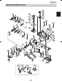
SERVICE PARTS LIST .................................................................................25

English
15
Do not use any adapter plugs with earthed (grounded) power tools.
Unmodifi ed plugs and matching outlets will reduce risk of electric shock.
b) Avoid body contact with earthed or grounded surfaces, such as pipes,
radiators, ranges and refrigerators.
There is an increased risk of electric shock if your body is earthed or grounded.
c) Do not expose power tools to rain or wet conditions.
Water entering a power tool will increase the risk of electric shock.
d) Do not abuse the cord. Never use the cord for carrying, pulling or unplugging
the power tool.
Keep cord away from heat, oil, sharp edges or moving parts.
Damaged or entangled cords increase the risk of electric shock.
e) When operating a power tool outdoors, use an extension cord suitable for
outdoor use.
Use of a cord suitable for outdoor use reduces the risk of electric shock.
f) If operating a power tool in a damp location is unavoidable, use a residual
current device (RCD) protected supply.
Use of an RCD reduces the risk of electric shock.
3) Personal safety
a) Stay alert, watch what you are doing and use common sense when operating a
power tool.
Do not use a power tool while you are tired or under the infl uence of drugs,
alcohol or medication.
A moment of inattention while operating power tools may result in serious personal
injury.
b) Use personal protective equipment. Always wear eye protection.
Protective equipment such as dust mask, non-skid safety shoes, hard hat, or hearing
protection used for appropriate conditions will reduce personal injuries.
c) Prevent unintentional starting. Ensure the switch is in the off position before
connecting to power source and/or battery pack, picking up or carrying the
tool.
Carrying power tools with your fi nger on the switch or energising power tools that have
the switch on invites accidents.
d) Remove any adjusting key or wrench before turning the power tool on.
A wrench or a key left attached to a rotating part of the power tool may result in
personal injury.
e) Do not overreach. Keep proper footing and balance at all times.
This enables better control of the power tool in unexpected situations.
f) Dress properly. Do not wear loose clothing or jewellery. Keep your hair,
clothing and gloves away from moving parts.
Loose clothes, jewellery or long hair can be caught in moving parts.
g) If devices are provided for the connection of dust extraction and collection
facilities, ensure these are connected and properly used.
Use of dust collection can reduce dust-related hazards.

English
16
4) Power tool use and care
a) Do not force the power tool. Use the correct power tool for your application.
The correct power tool will do the job better and safer at the rate for which it was
designed.
b) Do not use the power tool if the switch does not turn it on and off .
Any power tool that cannot be controlled with the switch is dangerous and must be
repaired.
c) Disconnect the plug from the power source and/or the battery pack from the
power tool before making any adjustments, changing accessories, or storing
power tools.
Such preventive safety measures reduce the risk of starting the power tool
accidentally.
d) Store idle power tools out of the reach of children and do not allow persons
unfamiliar with the power tool or these instructions to operate the power tool.
Power tools are dangerous in the hands of untrained users.
e) Maintain power tools. Check for misalignment or binding of moving parts,
breakage of parts and any other condition that may aff ect the power toolʼs
operation.
If damaged, have the power tool repaired before use.
Many accidents are caused by poorly maintained power tools.
f) Keep cutting tools sharp and clean.
Properly maintained cutting tools with sharp cutting edges are less likely to bind and
are easier to control.
g) Use the power tool, accessories and tool bits etc. in accordance with these
instructions, taking into account the working conditions and the work to be
performed.
Use of the power tool for operations diff erent from those intended could result in a
hazardous situation.
5) Service
a) Have your power tool serviced by a qualifi ed repair person using only identical
replacement parts.
This will ensure that the safety of the power tool is maintained.
CAUTION
Keep children and infi rm persons away.
When not in use, tools should be stored out of reach of children and infi rm persons.
Planer Safety Rules:
— Wait for the cutter to stop before setting the tool down.
An exposed cutter may engage the surface leading to possible loss of control and
serious injury.

English
17
PLANER SAFETY WARNINGS
1. Hold the power tool by insulated gripping surface only, because the cutter may
contact its own cord. Cutting a “live” wire may make exposed metal parts of the
power tool “live” and could give the operator an electric shock.
2. Use clamps or another practical way to secure and support the workpiece to
a stable platform. Holding the work by your hand or against the body leaves it
unstable and may lead to loss of control.
3. Do not use the Planer with the blades facing upward (as stationary type planer).
SYMBOL
WARNING
The following show symbols used for the machine. Be sure that you understand their
meaning before use.
To reduce the risk of injury, user must read instruction manual.
SPECIFICATIONS
Voltage 220 V
Power Input 620 W
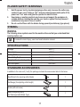
Cutting Width 82 mm
Max. Cutting Depth 2.6 mm
Weight (without cord and guide) 2.5 kg
No-Load Speed 17000 /min
STANDARD ACCESSORIES
In addition to the main unit (1 unit), the package contains the accessories listed in the below.
Box Wrench (for securing cutter blade) 1
Set Gauge (for adjusting cutter height)
1
Guide (with set screw)
1
Blade Sharpening Ass’y
(for Resharpenable Blade Type)
1

English
18
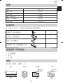
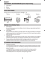
OPTIONAL ACCESSORIES (sold separately)
1. Dust adapter
2. Elbow
3. Dust bag
APPLICATIONS
Planing various wooden planks and panels. (See Fig. 1 ― 4)
Fig. 2
Beveling
Fig. 4
Tapering
9 mm
(Max)
Fig. 3
9 mm
(Max)
Rabbeting
82 mm (Max)
Fig. 1
Planing
PRIOR TO OPERATION
1. Power source
Ensure that the power source to be utilized conforms to the power requirements specifi ed on
the product nameplate.
2. Power switch
Ensure that the power switch is in the OFF position. If the plug is connected to a receptacle
while the power switch is in the ON position, the power tool will start operating immediately,
which could case a serious accident.
3. Extension cord
When the work area is removed from the power source. Use an extension cord of suffi cient
thickness and rated capacity. The extension cord should be kept as short as practicable.
4. Prepare a stable wooden workbench suitable for planing operation. As a poorly balanced
workbench creates a hazard, ensure it is securely positioned on fi rm, level ground.
PLANING PROCEDURES
1. Operation of the switch
The trigger switch lock-off button is designed to prevent inadvertent operation of the power
tool. To operate the power tool, it is necessary to fi rst fully insert the lock-off button into the
hole on the handle.
The trigger switch will not operate unless the lock-off button has been pushed in.
When the trigger switch is released, the power goes off and the lock-off button
automatically returns to its initial position, locking the trigger switch.

English
19
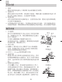
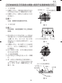
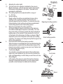
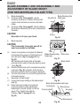
2. Adjusting the cutter depth
(1) Turn the knob in the direction indicated by the arrow in
Fig. 5 (clockwise), until the triangular mark is aligned with
the desired cutting depth on the scale. The scale unit is
graduated in millimeters.
(2) The cutting depth can be adjusted within a range of
0
-
2.6 mm.
3. Surface cutting
Rough cutting should be accomplished at large cutting
depths and at a suitable speed so that shavings are
smoothly ejected from the machine. To ensure a smoothly
fi nished surface, fi nish cutting should be accomplished at
small cutting depths and at low feeding speed.
4. Beginning and ending the cutting operation
As shown in Fig. 6, place the front base of the planer on
the material and support the planer horizontally. Turn ON
the power switch, and slowly operate the planer toward the
leading edge of the material. Firmly depress the front half
of the planer at the fi rst stage of cutting, as shown in Fig. 7,
depress the rear half of the planer at the end of the cutting
operation. The planer must always be kept fl at throughout the
entire cutting operation.
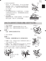
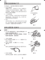
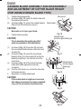
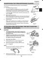
5. Precaution after fi nishing the planing operation
When the planer is suspended with one hand after fi nishing the
planing operation, ensure that the cutting blades (base) of the
planer do not contact or come too near your body. Failure to do
so could result in serious injury.
6. Cord holder (Fig. 8)
A cord holder is provided on the back of the handle below
where the cord is attached. Clip the cord in the holder from
right or left depending on which side you want the cord to be.
7. Stand (Fig. 9)
Lift the back of the planer to extend the foot from the base.
Having the stand extended when you put the planer down
prevents contact between the blade and the material.
Mark
Knob
Scale
Fig. 5
Fig. 6
Beginning of cutting operation
Fig. 7
End of cutting operation
Cord holder
Fig. 8
Stand
Fig. 9

English
20
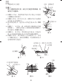
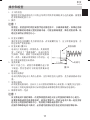
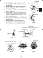
CARBIDE BLADE ASSEMBLY AND DISASSEMBLY
AND ADJUSTMENT OF CUTTER BLADE HEIGHT
(FOR DOUBLE EDGED BLADE TYPE)
1. Carbide blade disassembly
(1) As shown in Fig. 10, loosen the blade holder with
the attached box wrench.
(2) As shown in Fig. 11, remove the carbide blade by
sliding it with the attached box wrench.
CAUTION
Be careful not to injure your hands.
2. Carbide blade assembly
CAUTION
Prior to assembly, thoroughly wipe off all
swarf accumulated on the carbide blade.
(1) As shown in Fig. 12, lift set plate (B) and insert
the new carbide blade between cutter block and
set plate (B).
(2) As shown in Fig. 13, mount the new carbide
blade by sliding it on the set plate (B) so that the
blade tip projects by 1 mm from the end of the
cutter block.
(3) As shown in Fig. 14, fi x the bolts at the blade
holder after blade replacement has been
completed.
(4) Turn the cutter block over, and set the other side
in the same manner.
3. Adjustment of carbide blade height
CAUTION
If the carbide blade’s heights are inaccurate
after above procedures have been completed,
carry out the procedures described below.
Box wrench
Blade holder
Fig. 10
Carbide blade
(Double edged blade type)
Fig. 11
Set plate (B)
Carbide blade
(Double edged
blade type)
Fig. 12
Fig. 13
Fig. 14
ページが読み込まれています...
ページが読み込まれています...
ページが読み込まれています...
ページが読み込まれています...
ページが読み込まれています...
ページが読み込まれています...
ページが読み込まれています...
ページが読み込まれています...
-
 1
1
-
 2
2
-
 3
3
-
 4
4
-
 5
5
-
 6
6
-
 7
7
-
 8
8
-
 9
9
-
 10
10
-
 11
11
-
 12
12
-
 13
13
-
 14
14
-
 15
15
-
 16
16
-
 17
17
-
 18
18
-
 19
19
-
 20
20
-
 21
21
-
 22
22
-
 23
23
-
 24
24
-
 25
25
-
 26
26
-
 27
27
-
 28
28


Hitachi P 20SF Handling Instructions Manual
- カテゴリー
- パワーツール
- タイプ
- Handling Instructions Manual
他の言語で
- English: Hitachi P 20SF
関連論文
-
Hitachi D 6SH Handling Instructions Manual
-
Hikoki G10SQ ユーザーマニュアル
-
-
-
-
-
Hikoki G14DMR ユーザーマニュアル
-
Hikoki CJ 110MV ユーザーマニュアル
-
-
その他のドキュメント
-
Stanley STPP750 ユーザーマニュアル
-
-
-
-
Triton TCMPL ユーザーマニュアル
-
-
-
Bosch GHO 10-82 ユーザーマニュアル
-
DeWalt DW735 ユーザーマニュアル
-
Bosch GHO 185-LI ユーザーマニュアル