
zh
en
装配说明
请保存
Assembly instructions
please keep


zh
请将本说明保存在安全的地方,以备将来参考
安装技术人员操作说明
所有与安装、调整和燃气类型改装有关的操作都
必须由获得授权的安装技术人员根据所有适用的
规定、标准以及国家燃气和电力提供商的要求执
行。关于燃气类型的改装,建议您致电技术支持
服务。开始工作前,断开电器的电源和气源。
在将电器连接到安装设备之前,请先检查
确保其燃气类型与所供应的类型一致
(
参见
表
I)
。燃气灶的出厂设计为使用规格铭牌上
所示的燃气类型。
最重要的是,本电器的安装地点具有
符合规
定的适当通风条件
,可以将燃烧气体用管路
排到室外。
检查灶具尺寸以及厨柜中的切割孔尺寸。
工作面上方紧靠灶具的面板必须用
非易燃材
料
制作。层压表面和固定层压表面的胶水应
该耐热,以防性能变差。
任何电缆都不能接触灼热区域。
必须将电力电缆固定在家具模块上,防止其
接触烤箱或灶具的任何灼热部分。
带有电气部件的所有电器都必须
接地
。
在整个安装过程中小心处理电器。
不要让电
器与其它东西发生磕碰。
若不遵循本建议,由此导致的任何损坏将由
安装技术人员负责,制造商概不负责。
在家具模块中安装灶具
根据燃气电器标准
EN 30-1-1
,燃气灶在橱
柜内的位置为
3
级。
安装尺寸
1 -
最小距离
(mm)
。在工作面上切割一个具
有必要尺寸的孔口。图
1
。
如果不在
电气或混合
(
燃气和电子
)
灶具下
方安装烤箱,则在距离灶具底部
10 mm
处
放置一块非易燃材料隔板,例如胶合板或金
属,以防接近灶具下部。
如果不在
燃气
灶下方安装烤箱,建议在距离
燃气灶底部
10 mm
处放置一块非易燃材料
隔板,例如胶合板或金属,以防接近燃气灶
下部。
在电器下方有抽屉时,请确保抽屉中没有热
敏感或易燃物体,例如喷壶或鞋油。只能使
用耐热抽屉。
所有燃气灶
d < 150
电灶
10 < d < 150
如果要将灶具安装到烤箱上方,请检查并确
认烤箱装有强排风装置,并按照装配手册检
查尺寸。
将灶具放入橱柜模块上的插入孔切口中。
2 -
用于制作灶具模块的木质纤维在与湿气接
触时会极快膨胀。因此,我们建议使用专用
胶水处理切割边缘,以防蒸气或可能从炊具
单元工作表面下方滴落的冷凝水。
根据型号,可能已经安装了夹子和防水密封
件
(
灶具的下方
)
;在这种情况下,切勿将其
拆除。密封件确保整个工作台防水并防止水
渗透。密封件应放在内部外壳的边缘,应突
出约
3mm
。
如果出厂时未安装,请从灶具上拆下锅架和
燃气燃烧器盖板和扩散器,然后将其上下颠
倒。将随电器附带的粘性密封件安装到灶具
的下边缘
(
参见图
2a)
,从已安装的附件袋中
取出
U
型钉,将其固定在侧面的专用孔中。
图
2b
或
2c
。
3 -
沿着边缘按下,以使灶具沿着整个周围边
缘得到支撑
(
图
3)
。
如果您需要拆解电器,只要从下向上推即可
(U
型钉类型
2b)
。
如果您的灶具具有图
2c
中的
U
型钉类型,
则您必须使用螺丝起子将其撬起拆下。
图
2d
。
4 -
在煤气灶上,进气口末端带有
1
/
2
"
(20,955 mm)
螺纹,图
4
。该螺纹确保:
•
刚性连接。灶具附带有铜管、螺栓和防水密
封件。
•
使用可伸缩金属管
(
最短
1 m -
最长
3 m)
进行连接。此时,需要在歧管出口和供气
出口之间安装附件
9000060077
和密封件
(034308)
。图
4a
。如果是这样,您必须
防止管路接触插入单元
(
例如抽屉
)
的运动
部件或接近可能受阻的任何空间。
如果您需要水平连接气源,我们的技术服务
部门可以为您提供管接头
(
代码
173018)
和
密封件
(
代码
034308)
。
为了能够在法国使用该电器,有必要直接
连接至带有密封件
034308
的歧管出口。
图
4b
。相对于待安装厨柜中的孔,煤气管
位置如图
1b
所示。
确保已经安装的所有接头均密封。
制造商对安装技术人员安装的接头或相关的
泄漏不承担任何责任。
5 -
必须检查规格铭牌上的下列内容:电压和
总功率。
本电器必须接地。
必须确保所有接头都按照国家法规要求安
装。遵守当地供电公司的所有需求。
为了满足标准安全规定,安装技术人员必须
提供触点间隔至少为
3 mm
的单极切断开
关。如果使用插头连接,则不必要如此,只
要用户能够操作即可。
使用插头安装的所有电器都只能连接至已经
正确接地的插座。
本电器为“
Y
”型,这表明输入电缆不得由用
户更换,只能由该特定型号的维修技术人员
进行。必须注意电缆的横截面和类型。
不要对电器内部进行任何调整。如果有这种
需要,请致电我们的技术支持服务部门。
我们的灶具配备带或不带插头的电力电缆。
电缆类型:
灶具:
电源线:
所有燃气灶
3 x 0.75 mm
2
电灶
3 x 1.5 mm
2
6 -
为了完成安装,必须将燃烧器扩散器和
盖板安装到相应的环中。另外,也必须将平
底锅支承件放置在正确位置。图
5
。模块化
的灶具可以使用接口附件
NEZ34VLA
与电
器一同使用。图
1a
。如果将陶瓷灶具与电
器一同使用,需要使用的正确接口附件为
NEZ34VLB
;可以从我们的技术服务中心
获得。
改变燃气类型
所有与安装、调整和燃气类型改装有关的操作
都必须由获得授权的安装技术人员根据所有适用
的规定、标准以及国家燃气和电力提供商的要求
执行。
关于燃气类型的改装,建议您致电技术支持服
务。开始工作前,断开电器的电源和气源。
假如国家法规允许,本灶具可以改装为使用
其它类型的燃气。为此,必须执行下列所有
步骤:
A)
更改灶具上的燃烧器喷嘴。
1 -
拆除燃烧器的平底锅支架、盖板和主体。
2 -
使用
7 mm
套筒扳手更换燃烧头,确保
其拧紧到位以便正确密封。图
6
。
对于这些燃烧器,不必调整空气。
B)
调节燃烧器旋塞以减少能耗。
1 -
将气阀设置为最低。
2 -
从气阀拆除控制旋钮。图
7
。
3 -
拆下防溢出密封盘。
如果您的灶具安装时带有外部塑料密封盘,
则将螺丝起子插入盘中间的孔,然后将盘撬
起拆下。图
8
。
•
当您从孔
(
连接控制轴
)
中拆下密封盘时,
您将发现内部有一个由可伸缩橡皮管制成的
密封件;仅需使用螺丝起子的尖端推动密封
件,即可留出一定的空间来安装旋塞调整螺
钉
(
根据型号而定
)
。
请勿拆下内部把手。
4 -
调整旁通螺钉。
•
对于丙烷和丁烷燃气,必须向下拧紧螺钉。
•
对于天然气,转动螺钉
(
向左
)
直至燃烧器
产生所需的燃气量,确保当您把燃烧器控制
旋钮从最大转至最小时不会熄火或产生回焰
(
图
9a
或
9b
,根据型号而定
)
。
5 -
重要的是,必须确保所有的密封件固定
到位,从而确保一旦灶具上有溢出,不会
短路。
6 -
更换气阀上的控制旋钮。
请勿拆解旋塞轴
(
图
10)
:如果发生故障,请
更换整个旋塞。
C)
将电器气源已经改变的指示标签贴在铭牌
旁边。

en
Put these instructions in a safe place for future reference
Instructions for
the installation technician
All installation, regulation and adaptation to
other types of gas must be carried out by an
authorised installation technician, respecting
all applicable regulations, standards and
the country's electrical and gas supply
companies' specifications.
It is recommended that you call our Technical
Assistance Service for adaptation to other
types of gas. Before you begin, turn off the
appliance's electricity and gas supply.
Before connecting up the appliance to the
installation, first check that it has been adjusted
for the type of gas with which it is to be supplied
(see table I).Our cooking hobs leave the factory
designed to function with the type of gas that is
indicated on the specifications plate.
It is of the utmost importance that the place
in which the appliance is installed has suitable
ventilation in accordance with regulations so
that the combustion gases are piped outside.
Check the dimensions of the cooking hob as
well as the dimensions of the hole to be cut in
the kitchen unit.
The panels located above the work surface,
right next to the cooking hob, must be made of
non-inflammable material. Both the stratified
surfacing and the glue used to secure it should
be heat resistant, to prevent deterioration.
No electrical cables should come into contact
with hot areas.
The power cable must be secured to the
furniture module to prevent it from touching
any hot parts of the oven or the cooking hob.
All appliances containing any electrical
components must be earthed.
Handle the appliance with care during
the entire installation process. Do not hit the
appliance against anything.
IN THE EVENT THAT THIS ADVICE IS NOT
FOLLOWED, THE INSTALLATION TECHNICIAN
WILL BE RESPONSIBLE FOR ANY DAMAGE
CAUSED, AND THE MANUFACTURER WILL BE
EXEMPT FROM ALL RESPONSIBILITY.
Installing the cooking hob
in the furniture module
The positioning of a hob in a kitchen unit
is Class 3 according to the standard for gas
appliances EN 30-1-1.
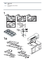
Fitting measurements
1 - Minimum distances (mm). Cut an aperture of
the necessary dimensions in the work surface.
Fig. 1.
If no oven is installed under an electrical or
mixed (gas and electric) hob, place a separator
of non-flammable material e.g. plywood or
metal at a distance of 10 mm. from the bottom
of the hob to prevent access to the lower part of
the hob.
If no oven is installed under a gas hob, it is
suggested to place a separator of non-
flammable material e.g. plywood or metal at a
distance of 10 mm. from the bottom of the hob
to prevent access to the lower part of the hob.
In the event that a drawer is located beneath
the appliance, please make sure that the drawer
contains no heat-sensitive or easily combustible
objects, such as spray cans or shoe polish. Use a
heat-resistant utility drawer only.
All gas d < 150
Electrical hob 10 < d < 150
If the cooking hob is to be installed above an
oven, check that the oven is fitted with power
ventilation, and check the dimensions according
to the assembly manual.
Place the cooking hob in the insertion
aperture cut into the furniture module.
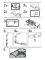
2 - The wood fibres that have been used to
make the cooking hob modules tend to swell
quite quickly when they come into contact with
moisture. We therefore recommend that the cut
edges are treated with a special glue to protect
them from steam or any condensation that
might drip down beneath the work surface of
the cooker unit.
Depending on the model, the clips and the
watertight seal (underside of the cooking hob)
may already be fitted; if this is the case, do not
under any circumstance remove them. The seal
ensures that the entire work surface will be
watertight, and prevents water seepage. The
seal is to be placed on the edge of the interior
housing and should protrude approximately
3mm.
If this item has not been fitted in the factory,
remove the pan supports and the gas burners
covers and diffusers from your cooking hob,
and turn it upside down. Now fit the adhesive
seal supplied with the appliance onto the lower
edge of the cooking hob (see Fig. 2a), remove
the staples from the attached accessories bag
and secure them into the lateral orifices that are
provided for this purpose. Fig. 2b or 2c.
3 - Press down all around the edges so that
the cooking hob is supported along its entire
perimeter (Fig. 3).
If you should need to dismantle the
appliance, simply push it upwards from
underneath (with staple type 2b).
If your cooking hob has the type of staple
shown in Fig. 2c, you will have to lever it up
with a screwdriver to dismantle it. Fig. 2d.
4 - On gas hobs, the end of the gas intake
comes with a
1
/
2
" (20,955 mm) thread, Fig. 4.
This thread ensures:
• A rigid connection. A copper pipe, a bolt
and a watertight seal are supplied together with
the cooking hob.
• Connection using a exible metal tube (L
min. 1 m - max. 3 m).ln this case, it is necessary
to install the accessory 9000060077 and
the seal (034308) between the outlet of the
manifold and the gas supply. Fig. 4a. With this
option, you must prevent the pipe from coming
into contact with moving parts of the insertion
unit (for example, a drawer) or access to any
spaces which might become obstructed.
If you need to connect the gas supply
horizontally, our technical services department
can supply you with an adaptor (code 173018)
and a seal (code 034308)
To be able to use this appliance in France, it is
necessary to carry out a direct connection to the
outlet of the manifold with the seal 034308. Fig.
4b. The position of the gas pipe, relative to the
hole in the kitchen unit where it is to be fitted is
shown in Fig. 1b.
Make sure that all the connections that
have been installed are airtight.
The manufacturer declines any responsibility
for leaks or for any connections installed by
the installation technician.
5 - The following must be checked on the
specifications plate: the voltage and the total
power. This appliance must be earthed.
Always make certain that all connections
that have been installed are in accordance
with national legal requirements. Observe all
the requirements of the local electrical supply
company.
In order to meet standard safety regulations,
the installation technician must provide
an omnipolar cut-off switch with a contact
separation of at least 3 mm. This is not
necessary if the connection is made via a plug,
so long as the user has access to it.
All appliances fitted with plugs should only
be connected up to sockets which have been
correctly earthed.
This appliance is type "Y", which means that
the input cable MUST NOT BE CHANGED BY THE
USER, only by the service technician for that
particular make. The section and type of cable
must be observed.
Do not make any adjustments in the interior of
the appliance. If this should be necessary, call
our technical assistance service.
Our cooking hobs are provided with a power
cable with or without a plug.
Types of cables:
Cooking hob: Power cable:
All gas 3 x 0.75 mm
2
Electrical hob 3 x 1.5 mm
2
6 - To complete the installation, the burner
diffusers and covers must be fitted onto their
corresponding rings. In addition, the pan
supports must also be located in their correct
places.
Fig. 5. Modular hobs may be combined with the
appliance using the joint accessory NEZ34VLA.
Fig. 1a. If a ceramic hob is to be combined with
the appliance, the correct joint accessory to
use is NEZ34VLB; these are available from our
technical service.
Changing gas type
All instalation, regululation and adaptation to
other types of gas must be carried out by an
authorised installation technician, respecting
all applicable regulations, standards and
the country's electrical and gas supply
companies' specifications.
It is recommended that you call our Technical
Assistance Service for adaptation to other
types of gas. Before you begin, turn off the
appliance's electricity and gas supply.
Provided that national laws so permit, this
cooking hob may be adapted to function with
other types of gas. To do so, all the following
steps should be carried out:
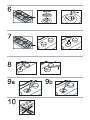
A) Change the nozzles of the burners on
the cooking hob.
1 - Remove the pan supports, covers and the
main body of the burner.
2 - Change the burner tips using a 7 mm
socket spanner and make sure that they are
tightened all the way in order to ensure that
they are correctly sealed. Fig. 6.
With these burners the air does not have to
be adjusted.
B) Adjust the burner taps for reduced
consumption.
1 - Turn the taps down to minimum.
2 - Remove the control knobs from the taps.
Fig. 7.
3 - Remove the anti-spillage disc seals.
If your cooking hob is fitted with exterior
plastic disc seals, remove them by inserting a
screwdriver through the discs' central orifice and
levering them out. Fig. 8.
• When you have removed the disc seals
from the orifice the control shaft emerges
from, you will find an interior seal made of
flexible rubber; simply push it with the tip of
the screwdriver to make room for you to work
on the tap adjustment screw, depending on the
model. Do not remove the interior grip.
4 - Adjust the By-pass screw.
• For propane and butane gas, the screw
must be screwed down tight.
• For natural gas, turn the screw (to the
left) until the burner is producing the desired
gas flow, in such a way that when you turn the
burner controls from maximum to minimum,
the flame does not go out, nor is there a flame
back draught created (Fig. 9a or 9b, depending
on the model).
5 - It is important to make sure that all the
seals are in place in order to ensure that, in the
case of spillages on the hob, there are no short
circuits.
6 - Replace the control knobs on the taps.
Do not dismantle the tap shaft (Fig. 10): In
the event of a malfunction, change the whole
tap.
C) Place the sticker indicating that the
appliance's gas supply has been changed
next to the specifications plate.

国家或地区
/
燃气 燃气已调 型号 类型
∑
Qn (kW)
G20
,
G25
∑
Qn (kW)
G30
,
G31
G20
(m3/h)
G25
(m3/h)
G30
(g/h)
G31
(g/h)
W V~ Hz
- - ET13051EU HSE-3FDE200 - - - - - - 50 Hz
I
3000 W 230 V~

COUNTRIES/GASES GAS ADJUSTED MODEL TYPE
∑
Qn (kW)
G20, G25
∑
Qn (kW)
G30, G31
G20
(m3/h)
G25
(m3/h)
G30
(g/h)
G31
(g/h)
W V~ Hz
- - ET13051EU HSE-3FDE200 - - - - - - 230 V~ 50 Hz
I
3000 W

代码
9000598165 B
-
 1
1
-
 2
2
-
 3
3
-
 4
4
-
 5
5
-
 6
6
-
 7
7
-
 8
8


他の言語で
- English: Siemens ET13051W/01 User manual
その他のドキュメント
-
Bosch PPW916B2TT/01 インストールガイド
-
-
-
-
-
-
Aeg-Electrolux HC411520GB ユーザーマニュアル
-
ROSIERES JZT-RGV63WFM PN ユーザーマニュアル
-
Ariston PH 741 RQO GH CN Operating Instructions Manual
-
Indesit PH 741 RQO GH CN ユーザーガイド