
HOBS
USER INSTRUCTIONS
GB - IE
灶具
使用说明书
CN
USINES DE ROSIÈRES - 30, rue Y. LACELLE - Rosières - 18400 - Lunery - France

安全说明
1. 安装说明
1.1 安装场所
1.2 适宜安装位置
2. 电气连接(仅适用于英国)
2.1 电气连接
2.2 燃气连接(仅适用于英国)
2.3 将灶具连接至不同类型的燃气
2.4 调节最小火焰
3. 灶具使用-用户使用说明
3.1 使用燃气燃烧器
3.2 使用灶具电热板
4. 维护与清洁
5. 售后服务
6. 环境保护
.........................................................................................08
.....................................................................................09
...................................................................................09
............................................................................09
..........................................................09
....................................................................................09
........................................................09
...................................................09
.............................................................................10
...............................................................10
.........................................................................10
.........................................................................10
..................................................................................10
.....................................................................................10
.....................................................................................10
CONTENT
Safety Instructions
1. Instructions For The Installer
1.1. Bulding In
1.2. Suitable Location
2. Electrical Connection (For U.K. Only)
2.1. Electrical Connection
2.2. Gas Connection (For U.K. Only)
2.3. Adapting The Hob To Different Types Of Gas
2.4. Regulating The Minimum Flame
3. Use Of Hob - User Instructions
3.1. Using The Gas Burner
3.2. Use Of Cooktop Electrical Plates
4. Maintenance and Cleaning
5. Aftercare
6. Protection Of The Environment
GB - IE
........................................................................04
.....................................................05
................................................................................05
....................................................................05
.......................................05
..............................................................05
..............................................05
.........................06
..............................................06
..................................................06
.............................................................06
............................................06
........................................................07
...................................................................................07
.................................................07
目录
CN
Gas Type Tables ............................................................12-13-14-15

03
accessible space
Niche accessible
Beschikbare ruimte
dostupan prostor
可用空间
Figure / 图 3
Min 10 mm
Sp.da 25 a 45 mm
A
B
Figure / 图 2Figure / 图 1
2
60 cm
2
240 cm
2
120 cm
2
180 cm
Figure / 图 5
1/2 GAS
CONICAL
C
A B
CYLINDRICAL
圆柱
CONICAL
圆锥体
INJECTOR / 注射器
Figure / 图 6
Figure / 图 7
Figure / 图 8
Seal / 密封
Bracket / 支架
Figure / 图10
Figure / 图 4
A: 56cm B: 59.5 / 74.5cm
A: 64cm B: 86cm
Figure / 图 9
Figure / 图 11
YES
正确
NO
错误
NO
错误
NO
错误
NO
错误

04 GB
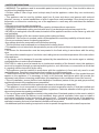
SAFETY INSTURUCTIONS
• WARNING: The appliance and its accessible parts become hot during use. Care should be taken to
avoid touching heating elements.
• Children under 8 Year of age must be kept away from the appliance unless they are continuously
supervised.
• This appliance can be used by children aged from 8 years and above and persons with reduced
physical, sensory or mental capabilities or lack of experience and knowledge if they have been given
supervision or instruction concerning use of the appliance in a safe way and understand the hazards
involved.
• Children must not play with the appliance.
• Cleaning and user maintenance shall not be made by children without supervision
• WARNING: Unattended cooking on a hob with fat or oil can be dangerous and may result in fire.
• NEVER try to extinguish a fire with water, but switch off the appliance and then cover flame e.g. with a lid
or a fire blanket.
• WARNING: Danger of fire: do not store items on the cooking surfaces.
• WARNING: If the surface is cracked, switch off the appliance to avoid the possibility of electric shock.
• Do not use a steam cleaner for cleaning operations.
• Any spillage should be removed from the lid before opening.
• The hob surface must be allowed to cool down before closing the lid.
• This appliance is not intended to be operated by means of an external timer or separate remote-control
system.
• The means for disconnection must be incorporated in the fixed wiring in accordance with the wiring
rules.
• The instructions state the type of cord to be used, taking into account the temperature of the rear surface
of the appliance.
• If the supply cord is damaged, it must be replaced by the manufacturer, its service agent or similarly
qualified persons in order to avoid a hazard.
CAUTION: In order to avoid a hazard due to inadvertent resetting of the thermal cutout, this appliance
must not be supplied through an external switching device, such as a timer, or connected to a circuit that
is regularly switched on and off by the utility.
• This appliance must be installed in accordance with the regulations in force and only used in a well
ventilated space. Read the instructions before installing or using this appliance.
• "These instructions are only valid if the country symbol appears on the appliance. If the symbol does not
appear on the appliance, it is necessary to refer to the technical instructions which will provide the
necessary instructions concerning modification of the appliance to the conditions of use of the country".
• "Prior to installation, ensure that the local distribution conditions (nature of the gas and gas pressure)
and the adjustment of the appliance are compatible";
• "The adjustment conditions for this appliance are stated on the label (or data plate)";
• "This appliance is not connected to a combustion products evacuation device. It shall be installed and
connected in accordance with current installation regulations. Particular attention shall be given to the
relevant requirements regarding ventilation".
• The use of a gas cooking appliance results in the production of heat and moisture in the room in which it
is installed. Ensure that the kitchen is well ventilated: keep natural ventilation holes open or install a
mechanical ventilation device (mechanical extractor hood). Prolonged intensive use of the appliance
may call for additional ventilation, for example opening of a window, or more effective ventilation, for
example increasing the level of mechanical ventilation where present.
• No additional operation/setting is required in order to operate the appliance at the rated frequencies

If an appliance is not fitted with a supply cord and a plug, or with other
means for disconnection from the supply mains having a contact
separation in all poles that provide full disconnection under
overvoltage category III conditions, the instructions shall state that
means for disconnection must be incorporated in the fixed wiring in
accordance with the wiring rules.
05 GB
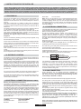
1. INSTRUCTIONS FOR THE INSTALLER
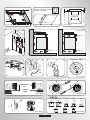
The hob may be installed in any worktop which is heat resistant to a
temperature of 100°C, and has a thickness of 25-45 mm. The
dimensions of the insert to be cut out of the worktop are in shown in
Figure 2.
If the Hob is fitted next to a cabinet on either side, the distance
between the Hob and the cabinet must be at least 15 cm (see Figure
4); while the distance between the hob and the rear wall must be at
least 5,5 cm.
The distance between the hob and any other unit or appliance above it
(e.g. An extractor hood) must be no less than 70 cm (Figure 4).
When there is an accessible space between the built-in hob and the
cavity below, a dividing wall made of insulating material should be
inserted (wood or a similar material) (Figure 3).
Important - The diagram in figure 1 shows how the sealant should
be applied.
The Hob unit is fitted by attaching the Fixing Clamps supplied, using
the holes at the base of the unit.
If a hob of 60 cm is fitted above an oven which is not equipped with fan
cooling system it is recommended that openings are created within
the built in furniture to ensure correct air circulation.
The size of these openings must be at least 300 cm2 and placed as
shown in Figure 5.
When a 75 cm hob is fitted over a built in oven, the latter must be fan
cooled.
This appliance is not intended to be operated by means of an external
timer or separate remote-control system.
2. ELECTRICAL CONNECTION (FOR U.K. ONLY)
Warning - this appliance must be earthed
This appliance is designed for domestic use only. Connection to the
main supply must be made by a competant electrician, ensuring that
all current regulations concerning such installations are observed.
The appliance must only be connected to a suitably rated spur point, a
3 pin 13 amp plug/socket is not suitable. A double pole switch must be
provided and the circuit must have appropriate fuse protection.
Further details of the power requirement of the individual product will
be found in the users’ instruction and on the appliance rating plate. In
the case of built-in product you are advised, should you wish to use a
longer cable than the one supplied, that a suitably rated heat resistant
type must be used.
The wiring must be connected to the mains supply as follows:
CONNECT TO SPUR TERMINAL
Green & Yellow Wire Earth Connection
Blue Wire Neutral Connection
INSTALLING A DOMESTIC APPLIANCE CAN BE A COMPLICATED OPERATION WHICH IF NOT CARRIED OUT CORRECTLY, CAN SERIOUSLY
AFFECT CONSUMER SAFETY. IT IS FOR THIS REASON THAT THE TASK SHOULD BE UNDERTAKEN BY A PROFESSIONALLY QUALIFIED
PERSON WHO WILL CARRY IT OUT IN ACCORDANCE WITH THE TECHNICAL REGULATIONS IN FORCE. IN THE EVENT THAT THIS ADVICE IS
IGNORED AND THE INSTALLATION IS CARRIED OUT BY AN UNQUALIFIED PERSON, THE MANUFACTURER DECLINES ALL RESPONSIBILITY
FOR ANY TECHNICAL FAILURE OF THE PRODUCT WHETHER OR NOT IT RESULTS IN DAMAGE TO GOODS OR INJURY TO INDIVIDUALS.
1.1 BUILDING IN
1.2. SUITABLE LOCATION
Check the data on the rating plate, located on the outside of the unit, to
ensure that the supply and input voltage are suitable.
Before connection, check the earthing system.
By Law, this appliance must be earthed. If this regulation is not
complied with, the Manufacturer will not be responsible for any
damage caused to persons or property. If a plug is not already
attached, fit a plug appropriate to the load indicated on the rating plate.
The earth wire is coloured yellow/green. The plug should always be
accessible.
Where the Hob is connected direct to the electricity supply, a circuit
breaker must be fitted.
If the power supply cord is damaged this is to be replaced by a
qualified engineer so as to prevent any potential risk.
The earth wire ( green and yellow coloured ) must be at least 10 mm
longer than the live and neutral wires.
The section of the cable used must be of the correct size in relation to
the absorbed power of the hob.
Please check rating plate for the power details and ensure that the
power supply cord is of the type 3x0.75 mm² H05 V2V2-F.
LIVE
EARTH
NEUTRAL
L
N
Power Cable
Brown Wire
Green/Yellow Wire
Blue Wire
Mains Supply
2.2. GAS CONNECTION
These instructions are for qualified personnel, installation of
equipment must be in line with the relevant national standard. (For
U.K. only: by law the gas installation\commissioning must be
carried out by a "Gas Safe" installer)
All work must be carried out with the electricity supply disconnected.
The rating plate on the hob shows the type of gas with which it is
designed to be used. Connection to the mains gas supply or gas
cylinder should be carried out after having checked that it is regulated
for the type of gas with which it will be supplied. If it is not correctly
regulated see the instructions in the following paragraphs to change
gas setting.
For liquid gas (cylinder gas) use pressure regulators which comply
with the relevant national standards.
Use only pipes,washers and sealing washers which comply with the
relevant national standards.
For some models a conic link is furnished to outfit for the installation in
the countries where this type of link is obligatory; in picture 8 it is
pointed out how to recognize the different types of links (CY =
cylindrical, CO = conic). In every case the cylindrical part of the link
has to be connected to the hob.
When connecting the hob to the gas supply via use offlexible hoses
please ensure that the maximum distance covered by the hose does
not exceed 2 metres.
This appliance must be installed in accordance with the regulations in
force and only used in a well ventilated space. Read the instructions
before installing or using this appliance.
A gas-powered cooking appliance produces heat and humidity in the
area in which it is installed. For this reason you should ensure good
ventilation either by keeping all natural air passages open or by
installing an extractor hood with an exhaust flue. Intensive and
prolonged use of the appliance may require extra ventilation, such as
the opening of a window or an increase in speed of the electric fan, if
you have one.
If a hood can not be installed, an electric fan should be fitted to an
outside wall or window to ensure that there is adequate ventilation.
The electric fan should be able to carry out a complete change of air in
the kitchen 3-5 times every hour. The installer should follow the
relevant national standards.
Brown Wire Live Connection
Note: We do not advocate the use of earth leakage devices with
electric cooking appliances installed to spur points because of the
«nuisance tripping» which may occur. You are again reminded that
the appliance must be correctly earthed, the manufacturer declines
any responsibility for any event occurring as a result of incorrect
electrical installation.
2.1. ELECTRICAL CONNECTION

06 GB
2.3. ADAPTING THE HOB TO DIFFERENT
TYPES OF GAS
To adapt the Hob for use with different types of gas, carry out the
following instructions:
•remove the grids and burners
•insert on hexagonal spanner (7 mm) into the burner support (Figure
7)
•Unscrew the injector and replace it with one suitable for the gas to be
used (see gas type table)
1)As illustrated, assemble parts in sequence:
A: 1/2 Male Adaptor Cylindirical
B: 1/2 Seal
C: 1/2 Female Gas Adaptor Conical-Cylindirical or
Cylindirical-Cylindirical
2)Tighten the joints with the spanner, remembering to twist the
pipes into position.
3)Attach fitting C to mains gas supply using rigid copper pipe or
flexible steel pipe.
IMPORTANT: carry out a final check for leaks on the pipe
connections using a soapy solution. NEVER USE A FLAME. Also,
make sure that the flexible pipe cannot come into contact with a
moving part of the cabinet (eg.adrawer) and that it is not situated
where it could be damaged.
Warning: If gas can be smelt in the vicinity of this appliance turn off the
gas supply to the appliance and call the engineer directly. Do not
search for a leak with a naked flame.
2.4. REGULATING THE MINIMUM FLAME
After lighting the burners, turn the control knob to the minimum setting
and then remove the knob (this can easily be removed by applying
gentle pressure).
Using a small «Terminal» type screwdriver the regulating screw can
be adjusted as in Figure 9. Turning the screw clockwise reduces the
gas flow, whilst turning it anticlockwise increases the flow – Use this
adjustment to obtain a flame of approximately 3 to 4 mm in length and
then replace the control knob.
When the gas supply available is LPG - the screw to set the idle flame
must be turned (clockwise) to the end stop.
When you have carried out the new gas regulation, replace the old gas
rating plate on your appliance with one (supplied with hob) suitable for
the type of gas for which it has been regulated.
3. USE OF HOB - USER INSTRUCTIONS
This appliance must only be used for the purpose for which it is
intended, domestic cooking, and any other use will be considered
improper and could therefore be dangerous. The Manufacturer will
not be responsible for any damage or loss resulting from improper
use.
3.1. USING THE GAS BURNER
To ignite the burners, place a lighted taper close to the burner, press in
and turn the control knob anti-clockwise.
If the burners have not been used for a couple of days, wait for a few
seconds before lighting the burner, this will allow any air present in the
pipes to escape.
For appliances fitted with electronic ignition carry out the following:
• push in and turn the knob anticlockwise to the ignition symbol.
• ignite the burner by pressing the sparker button.
For hobs fitted with automatic ignition simply push in and turn the knob
to the ignition symbol.
The ignition system will continue to generate sparks as long as the
control knob is being pressed.
If the burner has not ignited within 5 seconds, turn the knob to the 0
position and repeat the operation.
For smaller containers the gas burner should be regulated so that the
flame does not overlap the base of the pan. Vessels with a concave or
convex base should not be used.
The special removable support, supplied with some models,
must be used only on the auxiliary burner.
WARNING: If a flame is accidentally extinguished, turn the knob
to the off position and do not attempt to re-ignite if for at least 1
minute.
If over the years the gas taps become stiff to turn it is necessary to
lubricate them.
Such operation must be carried out only by qualified Service
Engineers.
The flexible tube shall be fitted in such a way that it cannot come into
contact with a moveable part of the housing unit (e.g. a drawer) and
does not pass through any space where it may become crushed/
kinked or damaged in any way.
To prevent any potential damage to the hob please carry out the
installation following this sequence (picture 6):
For models fitted with a safety tap (which cuts-off the flow of gas if the
flame is accidentally extinguished) the burners are ignited and
described above, but care must be taken.
Prior to switching on the gas hob ensure that the burners and burner
caps are correctly placed within their position.
GENERAL ADVISE
For best results, use cooking vessels with a flat surface. The size of
the surface should match the gas burner side as follows. Table A.
Suitability of Cooking Pans (Figure 11)
Keep in mind that larger pans have larger heating surfaces.
This will help them to cook the food faster than pans with smaller heating
surfaces.
Always use pan sizes proportionate to the amount of the food to be
cooked. In order to prevent splashing, do not use very small pans,
especially for foods with excess liquid. If you use excessively large pans
for quick cooked foods, sausages and liquids will stick and residues will
remain attached to the pan after being emptied.
Closed pans and baking trays or moulds are suggested for cooking
sweets. Splashed sugar and juices from an open pan may stick to the
cooker surface and will be difficult to remove.
This is especially important for pans used for roasting or pressurized
cooking at high temperature.
Do not leave burners unattended without a pan or with an empty pan on top.
Check the suitability of cooking pans with respect to the following criteria;
They should be heavy.
They should completely cover the burner surface; they may be a little
bigger but no smaller.
Base surfaces should be completely flat and fit well on the cooking surface.
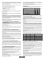
•For the best use of the electric hotplates and to minimize energy
consumption, only pans with smooth flat bases should be used. The size of
the pan should be as close as possible to the diameter of the hotplate, and
never smaller. The base of the pan should be dry and spillage should be
avoided. Empty pans must not be left on the plates, and the plates should
not be left switched on without a pan.
Turn the knob to the position for the required temperature of the hot plate.
The indicator light of the hot plate will come on and the hot plate will start to
heat.
When cooking is completed, turn the knob to the “ O” position. (Figure 10).
Do not leave the hot plate turned on without a pan on it. The diameter and
the base of the pan you use is critical. The maximum diameter of the pan
base is 14 cm and the base should be flat.
Leave the hot plate to heat up for 5 minutes before placing a pan on it the
first time you use it. This will allow the heat resistant coating of the plate to
harden due to burning.
Use a wet cloth and detergent for cleaning the hot plates. Do not remove
food residues from the hot plates with a knife or any other hard, sharp
object.
Turn on the hot plate for a few moments to dry it after cleaning. However, it
must never be left on for more than a few moments without a pan on top.
Position
Power (Watt)
Power (Watt)
Explanation
0
1
2
3
4
5
6
0
100 W
180 W
250 W
500 W
750 W
1000 W
0
135 W
220 W
300 W
850 W
1150 W
1500 W
Off
Heating
Cooking at low temperature
Cooking at low temperature
Cooking, Roasting, Boiling
Cooking, Roasting, Boiling
Cooking, Roasting, Boiling
3.2. USE OF COOKTOP ELECTRICAL PLATES
Table A
Burner Type
Ø pan / pot
Max(cm)
Auxiliary
AUX
Semi Rapid
SR
Rapid
R
18
24
26
Quadruple Crown/Double Crown Burner
QC/DC
26
Ø pan / pot
Mın (cm)
10
12
16
18
Triple Crown Burner
TC
26
18

4. MAINTENANCE AND CLEANING
Before cleaning the hob, ensure the appliance has cooled down.
Remove the plug from the socket or (if connected directly) switch off
the electricity supply.
Cleaning and user maintenance shall not be made by children without
supervision.
Never use abrasives, corrosive detergents, bleaching agents or
acids. Avoid any acid or alkaline substances (lemon, juice, vinegar
etc.) on the enamelled, varnished or stainless steel sections.
When cleaning the enamelled, varnished or chrome sections, use
warm soapy water or a non caustic detergent. For stainless steel use
an appropriate cleaning solution.
The burners can be cleaned with soapy water. To restore their original
shine, use a household stainless steel cleaner. After cleaning, dry the
burners and replace.
It is important the Burners are replaced correctly.
Chromed grids and burners
Chromed grids and burners have a tendency to discolour with use.
This does not jeopardize the functionality of the hob.
Our After Sales Service Centre can provide spare parts if required.
5. AFTERCARE
Before calling out a Service Engineer please check the following:
• that the plug is correctly inserted and fused;
• that the gas supply is not faulty.
If the fault cannot be detected:
Switch off the appliance and call the After Service Centre. DO NOT
TAMPER WITH THE APPLIANCE.
This appliance is marked according to the European
directive 2012/19/EU on Waste Electrical and
Electronic Equipment (WEEE). WEEE contains both
polluting substances (which can cause negative
consequences for the environment) and basic
components (which can be re-used). It is important to
have WEEE subjected to specific treatments, in order
to remove and dispose properly all pollutants, and
recover and recycle all materials.
Individuals can play an important role in ensuring that WEEE does not
become an environmental issue; it is essential to follow some basic
rules:
• WEEE shall not be treated as household waste.
• WEEE shall be handed over to the relevant collection points
managed by the municipality or by registered companies. In many
countries, for large WEEE, home collection could be present.
• When you buy a new appliance, the old one may be returned to the
retailer who has to collect it free of charge on a one-to-one basis, as
long as the equipment is of equivalent type and has the same
functions as the supplied equipment.
6. PROTECTION OF THE ENVIRONMENT
The Manufacturer will not be responsible for any inaccuracy resulting from
printing or transcript errors contained in this brochure. We reserve the right
to carry out modifications to products as required, including the interests of
consumption, without prejiudice to the characteristics relating to safety or
function.
Declaration of compliance: This equipment, in the parts intended to
come into contact with food, complies with the regulations laid down in
EEC directives 89/109.
This equipment, in the parts intended to come into contact with food,
complies with the regulations laid down in EEC directives 89/109.
The appliance complies with European Directive 2009/142/EC (GAD)
and starting from 21/04/2018 with Gas Appliances Regulation
2016/426 (GAR).
By placing the mark on this product, we are confirming
compliance to all relevant European safety, health and environmental
requirements which are applicable in legislation for this product.
07 GB
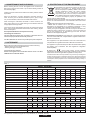
This appliance has been designed for non-professional, i.e. domestic, use only.
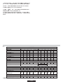
Table 1
1
1
1
1500
1 1 1 1 1 1
1
Gas Power (kW)
G20 20 mbar (N.G.) (l/h)
BUILT IN HOBS
Burners Arrangement
Auxiliary Burner (AUX)
Semirapid Burner (SR)
Rapid Burner (R)
Ultrarapid Burner (UR)
Quadruple Crown Burner (QC)
Triple Crown Burner (TC)
Double Crown Burner (DC)
Electric Plate
Flame Failure Device
Ignition
Installation Class
PLV7S
Type /Reference
3Gas
4Gas
3Gas+1E
5Gas 5Gas 5Gas 4Gas 4Gas 4Gas
YES
YES
PLV6S
3Gas 3Gas
1
-
1
-
-
-
1
-
1
-
1
-
-
1
-
-
1
-
1
-
1
-
-
1
2
1
-
-
-
-
1
2
-
-
-
-
-
1
1
2
-
1
-
-
1
1
2
-
-
1
-
1
1
2
-
-
-
1
-
-
-
1
1
1
-
1
-
-
-
1
1
1
-
-
1
-
-
1
1
1
-
-
-
1
-
3
595X510
3
3 3 3 3 3 3 3 3
745X510
745X510
860X510
-
-
-
1
Product Dimension (mmxmm)
Installed Gas Type / Power
Alternative Injector Kit For LPG Gas Available In The Packaging
Rated Power Input
Gas Power (kW)
G30/G31 28-30/37 mbar (LPG) (g/h)
Voltage (V) /Frequency (Hz)
Electrical Power (W)
3
7,5
7,3 7,1
7
4,5
11,35 11,55 11,75 8,85 9,05 9,25
714 695 676 667 429 1081 1100 1119 843 862 881
7,5
7,3 7,1
7
4,5
11,35 11,55 11,75 8,85 9,05 9,25
546 531 516 509 327 825 840 855 644 658 673
220-240 V / 50-60 Hz

08 CN
安全说明
• 警告:使用中电器及其可接触部件会发热,注意避免接触加热元件。
• 儿童除非年满8岁并且有人监督,否则应远离该电器。
• 8 岁以上儿童以及身体、感官或精神有缺陷的人员或缺乏经验和知识的人员,必须在有人监督的情况
下或被给予电器使用安全指导并了解相关危险的情况下,方可使用本电器。
• 严禁儿童玩耍该电器。
• 除非有人监督,否则儿童不得清洁本电器或执行用户维护操作。
• 警告:在灶具上烹肉或烹油时不得离开,否则存在危险,可能导致火灾。
• 切勿尝试用水灭火,而应关掉电器,并用盖子或防火毯盖住。
• 警告:当心火灾:切勿存放物品于工作台面。
• 警告:如表面存在裂痕,关掉电器,避免触电。
• 清洁时不得使用蒸汽清洗器
• 打开盖子之前,清理盖子上的溢出物。
• 应等灶具冷却后再盖上盖子。
• 不得使用外接定时器或独立的远程控制系统操作本电器。
• 断开方式必须与固定接线相匹配,并符合接线规则。
• 本使用说明书规定了使用的电线类型,考虑到了电器背面的温度。
• 如若电源线损坏,必须用从生产商或其服务代理人或具有类似资质的人员处获取专用电源线或组件进
行替换。
注意:为避免因疏忽而未复位热熔断器而导致危险,不得利用定时器等外部开关设备供电,也不得连
接至定期开关的电路。
• 本电器必须依据现行规定安装,而且仅能在通风良好的场所使用。在安装或使用本电器之前,阅读本
使用说明书。
• 仅当电器有国家标志时,这些使用说明有效。如果电器上无国家标志,需要参考技术说明书。该技术
说明书对于电器在该国家的使用条件修订进行说明。
• "安装之前,确保本地配置条件(燃气和气压条件)和电器调整兼容。"
• "有关该电器的调整条件,详见标签(或铭牌)"。
• 本电器不得连接于燃烧产物疏散设备。安装和连接应符合现行安全规则的要求,而且应特别注意通风
的相关要求。
• 使用燃气灶具,会使安装室内温度升高,湿度加大,所以应确保厨房友良好通风:请保持自然通风孔
打开或安装一个机械通风装置(机械抽风机罩)。电器长期开大火力使用时,需要更好的通风,例如
打开窗户或提高机械通风(如有)水平等更有效的通风措施。
• 需额外的操作/设置即可在额定频率下操作设备
安全说明

09 CN
1. 安装说明
灶具必须安装于耐热的场所,耐热温度为100℃,厚度是25-45mm。
工作场所的嵌入物的尺寸如图2所示。
如果灶具安装的位置的任一侧邻近柜子,灶具和柜子之间的距离应至
少为15cm(参见图4);同时灶具和后墙的距离至少为5.5cm。
灶具和任何装置或其上的电器(如抽风机罩)的距离应少于70cm
(参见图4)。
如果嵌入式灶具和下面空腔之间有可用空间,应嵌入由绝缘材料(木
头或类似材料)制成的隔墙(图3)。
重要提示-图1显示如何使用密封剂。
灶具是通过安装固定夹,利用装置底部的孔进行安装的。
如果一个60cm的灶具安装在一个烤箱之上,而且该烤箱未配置风机
散热系统时,建议在嵌入式家具之间设置开孔以确保适宜的空气流
通。
这些开孔的尺寸应至少为300cm2,位置如图5所示。
如果一个75cm的灶具安装于一个嵌入式烤箱上方,该嵌入式烤箱必
须配置风机散热。
本电器不得以外接电器或独立的遥控系统进行操作。
家用电器的安装操作可能较为复杂,安装错误会严重威胁消费者的安全。因此,电器的安装必须由专业、有资质的士依据现行的技术
规范执行。如果忽略此建议或者由不合格人士进行安装,对于本产品的技术故障,无论是否导致产品损害或人员伤害,生产商均不承
担任何责任。
1.1. 安装场所
1.2. 适宜安装位置
本电器必须依据现行规定进行安装,而且仅可以用于通风良好的场
所。安装和使用本电器之前,请阅读本使用说明书。
燃气灶具的使用会在室内产生热量和湿气,因此应确保厨房通风良
好:保持打开自然通风孔或安装一个具有烟道的机械通风装置(机械
抽风机罩)。电器长期大火力使用时,需要更好的通风,例如打开窗
户或加快电风扇(如有)的速度。
如无法安装机罩,为确保足够的通风,应在外墙或窗户上安装一个电
风扇。
电风扇可以每小时对厨房空气进行3-5次换气。安装人员应遵循相关
的国家标准。
火线
地线
中线
L
N
电源电缆
棕线
绿/黄线
蓝线
电源线
2.2. 燃气连接(仅适用于英国)
这些说明适用于专业人士,设备的安装必须符合相关的国家标准。
(仅适用于英国:依据法律规定,燃气安装/调试必须由安全燃气中
心的安装人员进行)
所有工作均必须在切断电源后进行。
灶具上的铭牌显示了规定使用的燃气类型。电源或燃气连接之前,
必须检查燃气类型与指定类型是否一致。如未能正确指定,参见以
下各段的说明改变燃气设置。
对于液态燃气(筒装燃气),请采用符合相关国家标准的压力调节
器。
仅使用符合相关国家标准的管道、垫圈和密封垫圈。
对于某些型号,提供圆锥链路以便在对链路具有强制性要求的国家
进行安装;在图8中指明了如何识别不同的链路(CY=圆柱形、
CO=圆锥形)。在任何情况下,链路的圆柱部分必须连接至灶具。
当通过使用柔性软管将灶具连接至燃气供应时,请确保软管覆盖的
最大距离不超过2m。
柔性管的安装方式应使其不会与家用装置(如抽屉)的可移动部分
接触,而且也不会穿过任何会使得管道以任何方式变形、弯曲或损
坏的场所。
为防止对灶具造成任何潜在损坏,请按照如下顺序进行安装(图
6):
1)如图所示,按照如下顺序装配各部件:
A:1/2外螺纹连接圆柱体
B:1/2密封
C:1/2 内螺纹燃气连接圆锥-圆柱或圆柱-圆柱
2)用扳手拧紧接头,注意转动管道到位。
3)使用刚性铜管或柔性钢管连接配件C至燃气供应。
重要提示:利用肥皂液最后检查管道连接是否存在泄漏。切勿使用
火焰。同 时 ,确保柔性管道不会 触 碰到柜子的移动部分 ( 如抽
屉),而且不得位于可能导致其损害的位置。
警告:如果家用电器部分发出燃气味道,关掉电器的燃气供应,并
直接打电话给工程师。不得用明火查找泄漏。
2. 电气连接(仅适用于英国)
警告-本电器必须接地
本产品是专为家庭使用而设计。与电源的连接必须由有资质的电工完
成,确保遵循所有相关规定。
电器必须连接至一个适宜、规定的支线点,3芯13安培的插头/插座不
适用。应提供一个双极开关,而且电路应配有适当的熔断保护。有关
个别产品的电源要求,详见用户使用说明和电器铭牌。就向您推荐的
嵌入产品而言,您需要使用比供应的电缆更长的电缆,即必须使用适
宜、额定、耐热型。
电源接线连接必须按照如下方式:
检查装置外部铭牌上的数据,确保电源和输入电压正确。
在连接之前,检查接地系统。
依据法律,该电器必须接地。如果未遵循此规定,生产商应对因此造
成的人员或财产损害负责。如果本身未安装插头,安装一个与铭牌所
示负载适宜的插头。接地线为黄线/绿线。插头应始终可用。
如果电器未配置电源线和插头,或无其他可与电源断开连接的方式,
但所有极点都有接触分离,可以在过压类型3的环境下进行完全断
开,说明书应说明断开方式必须与固定接线相一致,符合接线规定。
2.1. 电气连接
连接
至支线终端
绿线/黄线
蓝线
棕线
接地连接
中线连接
火线连接
注意:我们不提倡安装至支线的电动烹饪用具使用接地漏电设备,因
为可能发生跳闸。再次提醒您电器必须正确接地,因不正确的电器安
装造成的任何事件,生产商均不承担责任。
如果灶具直接连接至电源,应配置一个断路器。
如果电源线损坏,应由合格的工程师进行更换以避免任何潜在危险。
接地线(绿线和黄线)必须比火线和中线长10mm。
使用的电缆部分大小适宜,与灶具电线的消耗功率 相关。
请检查铭牌了解功率详情,并确保电源线是3×0.75mm2H05V2V2-F。
2.3. 将灶具连接至不同类型的燃气
为将灶具连接至不同类型的燃气,遵循以下说明:
• 移除烤架和燃烧器
• 将六角扳手(7mm)嵌入燃烧器支架内(图7)
• 旋松注射器,并使用与将用燃气(参见燃气类型表)适合的注射器
替换。

10 CN
2.4. 调节最小火焰
点燃燃烧器后,将控制旋钮调到最小设置值,并移除旋钮(通过轻
压可以轻松地移除旋钮)。
使用小型的终端类型螺丝刀,可如图9所示调节螺丝。顺时针旋转螺
丝可以减少气流量,反方向旋转则会增加流量-利用此调整获取长度
约为3-4mm的火焰,然后更换控制按钮。
如可用的燃气是液化石油气-设置闲置火焰的旋钮应被旋转(顺时
针)至末端。
如果您已经进行了新燃气调整,用调整后的与燃气类型匹配的铭牌
(由灶具提供)替换电器上的旧铭牌。
3.1. 使用燃气燃烧器
为点燃燃烧器,将点燃的蜡烛放置于附近,按压并以逆时针方向旋转
控制旋钮。
如果几天未使用燃烧器,在点燃之前等待几秒可释放管道中的所有空
气。
对于安装有电子点火器的电器,执行如下操作:
• 以逆时针方向推动和旋转旋钮至点火标志。
• 按下火花按钮点燃燃烧器。
对于装配有自动点火器的灶具,推动并旋转旋钮至点火标志。
只要按下控制旋钮,点火系统将继续生成火花。
如果在5s内未点燃燃烧器,旋转旋钮至O位置,并重复此操作。
对装配有安全旋塞(如果火焰意外熄灭,该旋塞将切断气流)的型
号,燃烧器将如上所述进行点燃,但必须谨慎。
在打开煤气灶之前,确保燃烧器和燃烧器盖正确放置在位置上。
一般建议
为获得最佳结果,在平整表面使用烹饪用具。表面的距离必须与煤气
灶匹配,如下所示。表A。
3. 灶具使用-用户使用说明
该电器必须仅用于设计目的,家用灶具和其它任何使用将视为是不
恰当并且危险的。对于不当使用造成的任何损害或损失,生产商不
承担任何责任。
转动旋钮至所需的电热板温度。热板指示灯点亮,电热板开始加热。
烹饪完成后,转动旋钮至"O"位置(图10)。当电热板上无电锅时切
勿打开。使用的电锅的尺寸和底面十分重要。最大的尺寸是14cm,
底面平整。
在首次使用电热板时,放置锅之前将电热板加热5分钟。如此可以令
电热板耐热涂层因加热而变硬。
使用湿布和清洁剂清洗热板。切勿用小刀或其他任 何硬质尖锐物体清
楚电热板上残留的食物。
清洁后,启动电热板以促使其变干。然而,在电热板上无电锅时启动
时间不要太长。
位置
功率 (瓦特)
功率 (瓦特)
说明
0
1
2
3
4
5
6
0
100 W
180 W
250 W
500 W
750 W
1000 W
0
135 W
220 W
300 W
850 W
1150 W
1500 W
关闭
谨记大的平底锅加热面积较大。
相对于加热面积较小的平底锅,大的平底锅可以更快地烹煮食物。
始终使用适合烹煮食物量的平底锅。为避免溅出,切勿使用小型的
平底锅,尤其是液体较多的食物。如果使用的平底锅快速烹煮食
物、香肠和液体,会导致粘锅,并且倒出食物后会有食物残留。
烹煮甜食时建议使用盖盖蒸锅和烤盘或烤模。因为无盖蒸锅溅出的
糖汁可能会粘住炊具表面,很难清理。
对于使用平锅进行高温烘烤或高压烹煮时尤为重要。
当燃烧器上无平锅或有空锅时,不要离开。
依据下列标准检查平底锅的适用性;
平底锅应较重。
底面完全平坦而且与烹煮面配合完好。
• 为发挥电热板最佳效能,并将能耗降至最低,仅能使用底面平滑平
整的平底锅。而且其大小应尽可能接近电热板的尺寸,不得比电热
板尺寸小。平底锅的底面干燥,并且避免有溢出物。不得将空锅放
置在电热板上,而且电热板上无平底锅时,不得处于开启状态。
表 A
辅助燃烧器(AUX)
半快速燃烧器(SR)
18
24
26
10
12
16
26
18
26
18
3.2. 使用灶具电热板
燃烧器类型
Φ平底锅/
锅 最小
(cm)
Φ平底锅/
锅 最大
(cm)
快速燃烧器(R)
四冠燃烧器/双冠燃烧器(QC/DC)
三冠燃烧器(TC)
对于小容器,应调整燃气燃烧器使得火焰不会与平底锅底部重叠。不
得使用含有凹面或凸形底的容器。
某些型号配有特殊的可移动支架,该支架必须仅用于辅助燃烧器。
警告:如果火焰意外熄灭,旋转旋钮至关闭位置,而且切勿尝试重新
点燃,至少等1分钟。
如长时间使用后,燃气开关很难转动,有必要对其进行润滑。
此类操作需由有资质的售后服务工程师执行。
加热
低温烹煮
低温烹煮
烹煮、烘烤、烧水
烹煮、烘烤、烧水
烹煮、烘烤、烧水
4. 维护与清洁
清理灶具之前,确保电器已经冷却。移除插座上的插头或(如直接
连接)关闭电源。
在无人监督的情况下,儿童不得对电器进行清理和 执行用户维修操
作。
不得使用研磨和腐蚀性清洁剂、漂白剂或酸。避免在涂漆或不锈钢
部分使用任何酸性或碱性物质(柠檬、果汁、醋等)。
在清洁涂漆或镀铬的部件时,使用温肥皂水或非腐蚀性清洁剂。对
于不锈钢则使用适宜的洗涤液。
燃烧器可以用肥皂水清洁。为恢复燃烧器的原有亮泽,可以使用家
用不锈钢清洁剂。在清洁后,使燃烧器干燥并更换。
正确更换燃烧器十分重要。
镀铬烤架和燃烧器
镀铬烤架和燃烧器可能会随着使用而变色,但不会损害灶具的功能
性。
如需要,我们的售后服务中心可以提供备用件。
5. 售后服务
在呼叫售后服务工程师之前,请检查以下各项:
• 插头是否正确插入和熔断;
• 燃气供应是否故障。
如果未发现故障:
关掉电器并呼叫售后服务中心。不得随意更改该电器。
本产品标 识 符 合 欧盟指令 : 报 废的电子 电 气 设 备
(2012/19/EU)。报废的电子电气设备包括污染物质
(会对环境产生负面影响)基础元件(可以重新利
用)。对于报废的电子电气设备进行特殊处理十分 重
要,以便正确去除和处理所有污染物,并回收和再利
用所有材料。
在确保报废的电子电气设备不会造成环境问题时,个
人扮演着至关重要的角色;必须遵循这些基本规定:
不得将报废的电子电气设备当做生活垃圾处理。
需要将报废的电子电气设备移交至市政或注册公司管理的相关收集
点。在很多国家,对于大的报废的电子电气设备,均有本地收集点。
6. 环境保护

表 1
本电器设计用于家用等非专业用途。
1
1
1
1500
1 1 1 1 1 1
1
燃气功率(kW)
G20 20 mbar (天然气) (l/h)
内嵌式灶具
PLV7S
类型/参照编号
3个
4个
3 +1E个
5个 5个 5个 4个 4个 4个
是
是
PLV6S
3个 3个
1
-
1
-
-
-
1
-
1
-
1
-
-
1
-
-
1
-
1
-
1
-
-
1
2
1
-
-
-
-
1
2
-
-
-
-
-
1
1
2
-
1
-
-
1
1
2
-
-
1
-
1
1
2
-
-
-
1
-
-
-
1
1
1
-
1
-
-
-
1
1
1
-
-
1
-
-
1
1
1
-
-
-
1
-
3
595X510
3
3 3 3 3 3 3 3 3
745X510
745X510
860X510
-
-
-
1
安装的燃气类型 / 功率
额定注射器套装,放入包装中,适用于LPG燃气
额定功率输入
燃气功率(kW)
G30/G31 28-30/37 mbar
(天然气) (l/h)
电压(V)频率(Hz)
电源(W)
3
7,5
7,3 7,1
7
4,5
11,35
11,55 11,75 8,85 9,05 9,25
714 695 676 667 429 1081 1100 1119 843 862 881
7,5
7,3 7,1
7
4,5
11,35
11,55 11,75 8,85 9,05 9,25
546 531 516 509 327 825 840 855 644 658 673
220-240 V / 50-60 Hz
11 CN
• 当您购买新的电器时,旧的电器可以返回至零售商,零售商可以免
费一对一收取,只要设备是同等类型,而且与提供的设备功能相同。
符合声明: 本设备将接触食物的部分符合EEC指令89/109的规定。
本电器符合欧盟指令2009/142/EC及其后续修订。
本电器贴 标识,表明本电器符合所有相关的欧洲安全、
健康和环境要求,与本产品的法律规定一致。
对于本手册中的因打印导致的失实或记录错误,生产商不承担责任。
我们保留必要时修改产品的权利,包括消费权利,不会损害安全或功
能特点。
燃烧器布置
辅助燃烧器(AUX)
半快速燃烧器(SR)
快速燃烧器(R)
超快速燃烧器(UR)
四环燃烧器(QC)
三冠燃烧器(TC)
双冠燃烧器(DC)
电板
熄火装置
点火装置
安装类别
产品尺寸(mm ×mm)

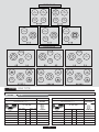
12
TYPE PLV6S
TYPE PLV7S
AUX
1 kW
DC
3.9-4.1
kW
SR
1.75 kW
R
2.5 kW
AUX
1 kW
DC
3.9-4.1
kW
SR
1.75 kW
R
2.5 kW
AUX
1 kW
TC
3.3-3.8
kW
AUX
1 kW
TC
3.3-3.8
kW
SR
1.75 kW
R
2.5 kW
AUX
1 kW
QC
3.6 kW
AUX
1 kW
QC
3.6 kW
SR
1.75 kW
R
2.5 kW
AUX
1 kW
SR
1.75 kW
Electric
plate
电板
1500W
SR
1.75 kW
AUX
1 kW
SR
1.75 kW
R
2,5 KW
TC
3.3-3.8
kW
AUX
1 kW
R
2.5 KW
QC
DC 3.6
kW
AUX
1 kW
R
2.5 KW
DC
3.9-4.1
kW
AUX
1 kW
TYPE PLV6S PLV7S
II2H3B/P
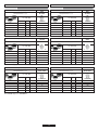
Gas type/燃气类型
G20
Gas pressure/燃气压力
20 mbar
CH - AT
AUX
SR
R
QC
P / 功率 (Kw)
Max/最大 (kW)
1
1.75
2.50
0.25
0.40
0.60
72 X
97 Z
109 Y
1/100mm
3.60
1.75
138
95
167
238
343
l/h
TC
3.80
1.75
151 H3
362
DC
4.00 1.75
151 H3
281
G30/G31
50/50 mbar
Gas type/燃气类型
Gas pressure/燃气压力
Max/最大 (kW)
Min/最小 (kW)
AUX
SR
R
1
1.75
2.50
0.35
0.50
0.75
P / 功率 (Kw)
43 H2
58 M
72 0
QC
3.60
2.15
85
73
127
182
261
g/h
1/100 mm
KIT CODE/设备代码 35000255
TC
3.80
2.15
77 F4
276
GAS TYPEHOBS
DC
3.80
2.15
78 F4
291
Min/最小 (kW)

13
II 2H3B/P
Gas type/燃气类型
G20
Gas pressure/燃气压力
20 mbar
AUX
SR
R
BG, HR, DK, EE, FI, LV, LT, NO, RO, SK, SE, SI, CZ, TR
P / 功率 (Kw)
Max/最大 (kW)
Min/最小 (kW)
1.00
1.75
2.50
0.25
0.40
0.60
72 X
97 Z
109 Y
1/100mm
95
167
238
l/h
QC
3.60 1.75
138
343
G30 / G31
30/30 mbar
Gas type/燃气类型
Gas pressure/燃气压力
AUX
SR
R
1.00
1.75
2.50
0.25
0.40
0.60
P (Kw)
50
65
80
1/100 mm
QC
3.60
1.75
94
73
127
182
261
g/h
TYPE PLV6S PLV7S
II 2L3B/P
Gas type/燃气类型
G25
Gas pressure/燃气压力
25 mbar
NL
AUX
SR
R
QC
P (Kw)
1.00
1.75
2.50
0.25
0.40
0.60
72 F1
102 F3
115 F2
1/100mm
3.60 1.75
140
110
194
277
400
l/h
G30 / G31
30/30 mbar
Gas type/燃气类型
Gas pressure/燃气压力
AUX
SR
R
1.00
1.75
2.50
0.25
0.40
0.60
P (Kw)
50
65
80
1/100 mm
QC
3.60
1.75
94
73
127
182
261
g/h
TYPE PLV6S PLV7S
KIT CODE/设备代码 35000251
3.80 1.75
151 H3
TC
TC
3.80
1.75
98
TC
3.80 1.75
148 F3
TC
3.80
1.75
98
362
276
421
276
DC
4.00 1.75
151 H3
381
DC
4.00 1.75
148 F3
443
DC
4.00 1.75
100
291
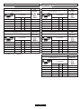
G20 / G25
20 / 25 mbar
AUX
SR
R
1.00
1.75
2.50
0.25
0.40
0.60
72 X
97 Z
109 Y
II 2E+3+
FR, BE
P / 功率 (Kw)
1/100mm
II 2H3+
CY, GB, GR, IE, IT, PT, ES, CH
Gas type/燃气类型
Gas pressure/燃气压力
QC
3.60 1.75
138
95
167
238
343
l/h
G20
20 mbar
AUX
SR
R
1.00
1.75
2.50
0.25
0.40
0.60
72 X
97 Z
109 Y
1/100mm
QC
3.60
1.75
138
95
167
238
343
l/h
TYPE PLV6S PLV7S TYPE PLV6S PLV7S
G30 / G31
28-30/37 mbar
AUX
SR
R
1.00
1.75
2.50
0.25
0.40
0.60
50
65
80
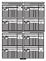
1/100 mm
73
127
182
g/h
QC
3.60
1.75
94
261
G30 / G31
28-30/37 mbar
AUX
SR
R
1.00
1.75
2.50
0.25
0.40
0.60
50
65
80
1/100 mm
73
127
182
g/h
QC
3.60
1.75
94
261
DC
4.00 1.75
100
291
DC
4.00 1.75
151 H3
381
DC
4.00 1.75
151 H3
381
DC
4.00 1.75
1.00
291
TC
3.80 1.75
98
276
TC
3.80
1.75
151 H3
362
TC
3.80
1.75
153 H3
362
TC
3.80
1.75
98
276
DC
4.00 1.75
1.00
291
Max/最大 (kW)
Min/最小 (kW)
Max/最大 (kW)
Min/最小 (kW) Min/最小 (kW)
Max/最大 (kW)
Max/最大 (kW)
Min/最小 (kW)
Gas type/燃气类型
Gas pressure/燃气压力
P / 功率 (Kw)
Max/最大 (kW)
Min/最小 (kW)
Gas type/燃气类型
Gas pressure/燃气压力
Max/最大 (kW)
Min/最小 (kW)
P / 功率 (Kw) P / 功率 (Kw)
Gas pressure/燃气压力
Gas type/燃气类型
Max/最大 (kW)
Min/最小 (kW)

II 2ELs3B/P
G20
20 mbar
PL
AUX
SR
R
QC
1.00
1.75
2.50
0.25
0.40
0.60
72 X
97 Z
109 Y
1/100mm
3.60 1.75
138
95
167
238
343
l/h
TYPE PLV6S PLV7S
II2HS3B/P
G20
25 mbar
HU
AUX
SR
R
QC
1.00
1.75
2.50
0.25
0.40
0.60
70 X
91 Z
108 F3
1/100mm
3.60 -
-
95
167
238
-
l/h
TYPE PLV6S PLV7S
KIT CODE/设备代码 35000250
TC
3.80
1.75
K 127
343
TC
3.80
1.75
151H3
362
DC
4.00
1.75
151H3
381
DC
4.00
1.75
145 H3
381
G2.350
13 mbar
AUX
SR
R
1.00
1.75
2.50
0.25
0.40
0.60
97 Y
124 Y
145 F2
1/100 mm
QC
3.60
1.75
182
132
231
331
468
l/h
G25.1
25 mbar
AUX
SR
R
1.00
1.75
2.50
0.25
0.40
0.60
72 F1
102 F3
115 F2
1/100 mm
QC
3.60
1.75
140
110
194
277
400
l/h
KIT CODE/设备代码 35000253 KIT CODE/设备代码 35000251
TC
3.30
1.75
200 H3
TC
3.80
1.75
148 F3
422
437
DC
4.00
1.75
205 H3
526
DC
3.90
1.75
148 F3
433
G30/G31
37/37 mbar
AUX
SR
R
1.00
1.75
2.50
0.30
0.45
0.65
46
61
73
1/100 mm
QC
3.60
1.95
89
73
127
182
261
g/h
G30/G31
30/30 mbar
AUX
SR
R
1.00
1.75
2.50
0.25
0.40
0.60
50
65
80
1/100 mm
QC
3.60
1.75
94
73
127
182
261
g/h
KIT CODE/设备代码 35000254
TC
3.80
1.95
93
TC
3.80
1.95
98
276 276
DC
4.00
1.95
94
291
DC
4.00
1.75
100
291
14
P / 功率 (Kw)
Gas type/燃气类型
Gas pressure/燃气压力
P / 功率 (Kw)
Min/最小 (kW)
P / 功率 (Kw)
Gas pressure/燃气压力
Gas pressure/燃气压力
Gas type/燃气类型
Gas type/燃气类型
Gas pressure/燃气压力
Max/最大 (kW)
Min/最小 (kW)
Max/最大 (kW)
Min/最小 (kW)
Max/最大 (kW) Max/最大 (kW)
Min/最小 (kW)
P / 功率 (Kw)
Gas pressure/燃气压力
Gas type/燃气类型 Gas type/燃气类型
Max/最大 (kW)
Min/最小 (kW)
P / 功率 (Kw)
Gas pressure/燃气压力
Gas type/燃气类型
Max/最大 (kW)
Min/最小 (kW)
P / 功率 (Kw)

69
II 2E3B/P
G20
20 mbar
AUX
SR
R
QC
DE
1.00
1.75
2.50
0.25
0.40
0.60
72 X
97 Z
109 Y
1/100mm
3.60
1.75
138
95
167
238
343
l/h
TYPE PLV6S PLV7S
TC
3.80
1.75
151 H3
362
DC
4.00 1.75
151 H3
381
TYPE PLV6S PLV7S
II2EK3B/P
G20
20 mbar
NL
AUX
SR
R
QC
1.00
1.75
2.50
0.25
0.40
0.60
72 X
97 Z
109 Y
1/100mm
3.60
1.75
138
95
167
238
343
l/h
TC
3.80
1.75
151 H3
362
DC
4.00 1.75
151 H3
381
G30 / G31
50/50 mbar
AUX
SR
R
1.00
1.75
2.50
0.35
0.50
0.75
43 H2
58 M
72 0
1/100 mm
QC
3.60
2.15
85
73
127
182
261
g/h
TC
3.80
2.15
77 F4
276
KIT CODE/设备代码 35000255
DC
4.00 2.15
78 F4
291
G25.3
25 mbar
AUX
SR
R
1.00
1.75
2.50
0.25
0.40
0.60
72 F1
102 F3
115 F2
QC
3.60
1.75
140
109
190
272
391
l/h
TC
3.30
1.75
145
359
DC
4.10
1.75
148 F3
446
G30 / G31
30/30 mbar
AUX
SR
R
1.00
1.75
2.50
0.25
0.40
0.60
50
65
80
1/100 mm
QC
3.60
1.75
94
73
127
182
261
g/h
TC
3.80
1.75
98
276
DC
4.00 1.75
100
291
1/100 mm
15
Max/最大 (kW)
Gas pressure/燃气压力
P / 功率 (Kw)
Gas type/燃气类型
Gas pressure/燃气压力
P / 功率 (Kw)
Max/最大 (kW)
Min/最小 (kW)
Gas pressure/燃气压力
P / 功率 (Kw)
Max/最大 (kW)
Min/最小 (kW)
Max/最大 (kW)
Min/最小 (kW)
P / 功率 (Kw)
Gas pressure/燃气压力
Gas type/燃气类型
Min/最小 (kW)
P / 功率 (Kw)
Gas type/燃气类型
Gas pressure/燃气压力
Gas type/燃气类型
Max/最大 (kW)
Min/最小 (kW)
Gas type/燃气类型

GB - IE
The manufacturer will not be responsible for any inaccuracy resulting from printing or transcript errors contained in this brochure. We reserve the right
to carry out modifications to products as required, including the interests of con sumption, without prejudice to the characteri stics relating to safety or
function.
42830165 • 70 gr - A4 • 04.2019 • Rev_A
CN
对于本手册中的因打印导致的失实或记录错误,生产生不承担责任。我们保留必要时修改产品的权利,包括消费权利,不会损害安全或功能特点。
-
 1
1
-
 2
2
-
 3
3
-
 4
4
-
 5
5
-
 6
6
-
 7
7
-
 8
8
-
 9
9
-
 10
10
-
 11
11
-
 12
12
-
 13
13
-
 14
14
-
 15
15
-
 16
16


他の言語で
- English: ROSIERES JZT-RGV63WFM PN User manual
その他のドキュメント
-
Ariston PH 741 RQO GH CN Operating Instructions Manual
-
Indesit PHN 932 T2/IX/A ユーザーガイド
-
Siemens ET13051W/01 ユーザーマニュアル
-
-
-
Bosch PRW926B20T ユーザーマニュアル
-
-
-
-