
PHN 932 T2/IX/A
English
Operating Instructions
HOB
Contents
Operating Instructions,1
Warnings,2
Assistance,3
Description of the appliance,4
Installation,5
Start-up and use,9
Precautions and tips,9
Maintenance and care,10
Troubleshooting,10
中文
操作说明
炉盘
目录
操作说明,1
警告,2
帮助,3
器具说明,4
安装,11
启动和使用,14
注意事项和技巧,14
维护与保养,14
故障排除,15

2
Warnings
WARNING: The appliance and its accessible parts
become hot during use. Care should be taken to
avoid touching heating elements. Children less than 8
years of age shall be kept away unless continuously
supervised. This appliance can be used by children
aged from 8 years and above and persons with
reduced physical, sensory or mental capabilities or
lack of experience and knowledge if they have been
given supervision or instruction concerning use of the
appliance in a safe way and understand the hazards
involved. Children shall not play with the appliance.
Cleaning and user maintenance shall not be made
by children without supervision.
WARNING: Unattended cooking on a hob with fat or
oil can be dangerous and may result in re. NEVER
try to extinguish a re with water, but switch off the
appliance and then cover ame e.g. with a lid or a
re blanket.
WARNING: Danger of re: do not store items on the
cooking surfaces.
Never use steam cleaners or pressure cleaners on
the appliance.
Remove any liquid from the lid before opening it. Do
not close the glass cover (if present) when the gas
burners or electric hotplates are still hot.
The appliance is not intended to be operated by
means of an external timer or separate remote
control system.
CAUTION: the use of inappropriate hob guards can
cause accidents.
警告
警告:本器具及其可用零件在使用过程中会变热。
应当小心,避免接触加热元件。不得让 8 岁以下
儿童靠近,除非一直有人看管。本器具可由 8 岁
及以上儿童、身体、感觉或智力能力减弱或缺乏经
验和知识的人使用,如果关于该器具的安全使用,
给予了监督或指导,并且他们了解有关的危险。儿
童不得玩耍该器具。在没有监督的情况下,儿童不
得进行清洁和用户维修。
警告:在无人看管的情况下在炉盘上用脂肪或油烹
饪,可能造成危险,并导致起火。切勿试图用水灭
火,而是要关掉器具开关,然后用盖子或防火毯等
盖住火焰。
警告:起火危险:不要在烹饪表面存放东西。
绝不要对器具使用蒸汽清洁器或压力清洁器。
打开前,除去盖上的任何液体。燃气器或电加热板
仍热着的时候,不要关闭玻璃罩(如果有)。
本器具不预期通过外部计时器或独立的远程控制系
统来操作。
小心:使用不当的炉盘防护装置会发生意外。

3
Assistance
Communicating:
• the type of problem
• appliance model (Mod.)
• serial number (S/N)
This information is found on the data plate located on the appliance and/or
on the packaging.
帮助
通信:
• 故障類型
• 器具型号 (Mod.)
• 序列号 (S/N)
此信息可在位于该器具和/或包装的数据标牌上找到。

4
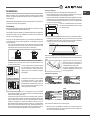
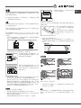
Description of the appliance
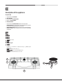
Overall view
1. Support Grid for COOKWARE
2. GAS BURNERS
3. Control Knobs for GAS BURNERS
4. Ignition for GAS BURNERS
5. SAFETY DEVICES
• Control Knobs for GAS BURNERS adjust the size of the ame.
• GAS BURNERS differ in size and power. Use the diameter of the cookware
to choose the most appropriate burner to cook with.
• GAS BURNER IGNITION enables a specic burner to be lit automatically.
• SAFETY DEVICE stops the gas flow if the flame is accidentally
extinguished.
器具说明
整体视图
1. 烹饪用具的支承网架
2. 燃气器
3. 燃气器的控制旋钮
4. 燃气器的点火器
5. 安全装置
• 燃气器的尺寸与功率有所不同。根据烹饪用具的直径,选择最合适的燃
烧器进行烹饪。
• 燃气器的控制旋钮可调节火焰的大小。
• 燃气器的点火器可让某一特定的燃烧器自动点燃。
• 安全装置将在火焰意外熄灭的情况下停止气流。
5
4
1
2
3

GB
5
Installation
! Before operating your new appliance please read this instruction booklet
carefully. It contains important information for safe use, installation and care
of the appliance.
! Please keep these operating instructions for future reference. Pass them on
to possible new owners of the appliance.
Positioning
! Keep packaging material out of the reach of children. It can become a choking
or suffocation hazard (see Precautions and tips).
! The appliance must be installed by a qualied professional according to the
instructions provided. Incorrect installation may cause harm to people and
animals or may damage property.
! This unit may be installed and used only in permanently ventilated rooms
in accordance with current national regulations). The following requirements
must be observed:
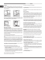
• The room must be equipped with an air extraction system that expels
any combustion fumes. This may consist of a hood or an electric fan that
automatically starts each time the appliance is switched on.
In a chimney stack or branched flue.
(exclusively for cooking appliances)
Directly to
the Outside
• The room must also allow proper air circulation, as air is needed for
combustion to occur normally. The ow of air must not be less than 2 m
3
/h
per kW of installed power.
The air circulation system may take air directly
from the outside by means of a pipe with an
inner cross section of at least 100 cm
2
; the
opening must not be vulnerable to any type
of blockages.
The system can also provide the air needed
for combustion indirectly, i.e. from adjacent
rooms fitted with air circulation tubes as
described above. However, these rooms must
not be communal rooms, bedrooms or rooms
that may present a re hazard.
• Intensive and prolonged use of the appliance may necessitate
supplemental ventilation, e.g. opening a window or increasing the power
of the air intake system (if present).
• Liquid petroleum gas sinks to the oor as it is heavier than air. Therefore,
rooms containing LPG cylinders must also be equipped with vents to allow
gas to escape in the event of a leak. As a result LPG cylinders, whether
partially or completely full, must not be installed or stored in rooms or
storage areas that are below ground level (cellars, etc.). It is advisable to
keep only the cylinder being used in the room, positioned so that it is not
subject to heat produced by external sources (ovens, replaces, stoves,
etc. ) which could raise the temperature of the cylinder above 50°C.
A
Examples of
ventilation holes
for comburant air.
Enlarging the ventilation slot
between window and floor.
Adjacent
Room
Room to be
Vented
Fitting the appliance
The following precautions must be taken when installing the hob:
• Kitchen cabinets adjacent to the appliance and taller than the top of the
hob must be at least 200 mm from the edge of the hob.
• Hoods must be installed according to their relative installation instruction
manuals and at a minimum distance of 650 mm from the hob (see gure).
• Place the wall cabinets adjacent to the hood at a minimum height of 420
mm from the hob (see gure).
If the hob is installed beneath a wall cabinet,
the latter must be situated at a minimum of 700
mm above the hob.
• The installation cavity should have the dimensions indicated in the gure.
Fastening hooks are provided, allowing you to fasten the hob to tops that
are between 20 and 40 mm thick. To ensure the hob is securely fastened
to the top, we recommend you use all the hooks provided.
475 mm.
835 mm.
min. 55 mm.
Before the installation remove the grids and burners from the hob and turn it
upside down, making sure you don’t damage the thermocouples and spark
plugs.
Apply the seals that come with the
appliance along the outer edges of
the hob to prevent any passage of air,
humidity and water (see Figure).
For proper application make sure the
surfaces to be sealed are clean, dry and
free of any grease/oil.
Hook fastening diagram
Hooking position for top H=20mm Hooking position for top H=30mm
Front
Hooking position for top H=40mm Back
! Use the hooks contained in the “accessory pack”.
• Where the hob is not installed over a built-in oven, a wooden panel must
be installed as insulation. This must be placed at a minimum distance of
20 mm from the lower part of the hob.
600mm min.
420mm min.
650mm min.

6
GB
Ventilation
To ensure adequate ventilation, the back panel of the cabinet must be
removed. It is advisable to install the oven so that it rests on two strips of
wood, or on a completely at surface with an opening of at least 45 x 560
mm (see diagrams).
560 mm.
45 mm.
Where a hob is installed above an oven without a forced ventilation cooling
system, adequate ventilation must be provided inside the cabinet by means
of air holes through which air can pass (see gure).
Electrical connection
Hobs equipped with a three-pole power supply cable are designed to operate
with alternating current at the voltage and frequency indicated on the data
plate (this is located on the lower part of the appliance). The earth wire in the
cable has a green and yellow cover. If the appliance is to be installed above
a built-in electric oven, the electrical connection of the hob and the oven must
be carried out separately, both for electrical safety purposes and to make
extracting the oven easier.
Connecting the supply cable to the mains
Install a standardised plug corresponding to the load indicated on the data
plate.
The appliance must be directly connected to the mains using an omnipolar
circuit-breaker with a minimum contact opening of 3 mm installed between the
appliance and the mains. The circuit-breaker must be suitable for the charge
indicated and must comply with current electrical regulations (the earthing
wire must not be interrupted by the circuit-breaker). The supply cable must
not come into contact with surfaces with temperatures higher than 50°C.
! The installer must ensure that the correct electrical connection has been
made and that it is compliant with safety regulations.
Before connecting to the power supply, make sure that:
• the appliance is earthed and the plug is compliant with the law.
• the socket can withstand the maximum power of the appliance, which is
indicated on the data plate.
• the voltage is in the range between the values indicated on the data plate.
• the socket is compatible with the plug of the appliance. If the socket is
incompatible with the plug, ask an authorised technician to replace it. Do
not use extension cords or multiple sockets.
! Once the appliance has been installed, the power supply cable and the
electrical socket must be easily accessible.
! The cable must not be bent or compressed.
! The cable must be checked regularly and replaced by authorised technicians
only (see Assistance).
! The manufacturer declines any liability should these safety measures not
be observed.
Gas connection
The appliance should be connected to the main gas supply or to a gas
cylinder in compliance with current national regulations. Before carrying out
the connection, make sure the cooker is compatible with the gas supply you
wish to use. If this is not the case, follow the instructions indicated in the
paragraph “Adapting to different types of gas.”
When using liquid gas from a cylinder, install a pressure regulator which
complies with current national regulations.
! Check that the pressure of the gas supply is consistent with the values indicated
in Table 1 (“Burner and nozzle specications”). This will ensure the safe operation
and longevity of your appliance while maintaining efcient energy consumption.
Connection with a rigid pipe (copper or steel)
! Connection to the gas system must be carried out in such a way as not to
place any strain of any kind on the appliance.
There is an adjustable L-shaped pipe tting on the appliance supply ramp
and this is tted with a seal in order to prevent leaks. The seal must always
be replaced after rotating the pipe tting (seal provided with appliance). The
gas supply pipe tting is a threaded 1/2 gas cylindrical male attachment.
Connecting a exible jointless stainless steel pipe to a threaded
attachment
The gas supply pipe tting is a threaded 1/2 gas cylindrical male attachment.
These pipes must be installed so that they are never longer than 2000 mm
when fully extended. Once connection has been carried out, make sure that
the exible metal pipe does not touch any moving parts and is not compressed.
! Only use pipes and seals that comply with current national regulations.
Checking the tightness of the connection
! When the installation process is complete, check the pipe ttings for leaks
using a soapy solution. Never use a ame.
Adapting to different types of gas
To adapt the hob to a different type of gas other than default type (indicated
on the rating plate at the base of the hob or on the packaging), the burner
nozzles should be replaced as follows:
1. Remove the hob grids and slide the burners off their seats.
2. Unscrew the nozzles using a 7 mm socket spanner, and replace them
with nozzles for the new type of gas (see table 1 “Burner and nozzle
characteristics”).
3. Reassemble the parts following the above procedure in the reverse order.
4. Once this procedure is nished, replace the old rating sticker with one
indicating the new type of gas used. Sticker are available from any of our
Service Centres.
• Adjusting the burners’ primary air
Does not require adjusting.

GB
7
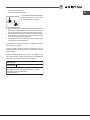
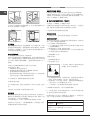
• Setting the burners to minimum
1. Turn the tap to the low ame position;
2. Remove the knob and adjust the adjustment
screw, which is positioned in or next to the tap
pin, until the ame is small but steady.
3. Having adjusted the ame to the required low setting, while the burner is
alight, quickly change the position of the knob from minimum to maximum
and vice versa several times, checking that the ame does not go out.
4. Some appliances have a safety device (thermocouple) tted. If the device
fails to work when the burners are set to the low ame setting, increase
this low ame setting using the adjusting screw.
5. Once the adjustment has been made, replace the seals on the by-passes
using sealing wax or a similar substance.
! If the appliance is connected to liquid gas, the regulation screw must be
fastened as tightly as possible.
! Once this procedure is nished, replace the old rating sticker with one
indicating the new type of gas used. Stickers are available from any of our
Service Centres.
! Should the gas pressure used be different (or vary slightly) from the
recommended pressure, a suitable pressure regulator must be tted to the
inlet pipe (in order to comply with current national regulations).
Electrical
connections
DATA PLATE
ECODESIGN
see data plate
This appliance conforms to the EU Regulation no. 66/2014
implementing Directive 2009/125/EC.
standard EN 30-2-1

8
GB
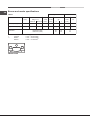
Table 1
Nominal (mbar)
Minimum (mbar)
Maximum (mbar)
20
17
25
28-30
20
35
37
25
45
Semi Rapid (S)
Triple Crown (TC)
Supply
pressures
Burner
Diameter
(mm)
Thermal Power
kW (p.c.s.*)
75
130
1.65
3.25
NominalReduced
0.40
1.50
By-pass
1/100
(mm)
28
61
Nozzle
1/100
(mm)
Flow*
g/h
***
64
91
Flow*
l/h
96 (Z)
133 (Z)
157
309
120
236
**
118
232
* A 15°C e 1013,25 mbar-dry gas
** Propane P. C.S. = 50.37 MJ/Kg
*** Butane P.C.S. = 49.47 MJ/Kg
Natural P.C.S. = 37.78 MJ/m
Burner and nozzle specifications
3
Nozzle
1/100
(mm)
Liquid Gas Natural Gas
PHN 932 T2/IX/A
TC
S
TC

GB
9
Start-up and use
! The position of the corresponding gas burner is shown on every knob.
Gas burners
Each burner can be adjusted to one of the following settings using the
corresponding control knob:
● Off
Maximum
Minimum
To light one of the burners, hold a lit match or lighter near the burner and, at
the same time, press down and turn the corresponding knob anti-clockwise
to the maximum setting.
Since the burner is tted with a safety device, the knob should be pressed
for approximately 2-3 seconds to allow the automatic device keeping the
ame alight to heat up.
When using models with an ignition button, light the desired burner pressing
down the corresponding knob as far as possible and turning it anticlockwise
towards the maximum setting.
! If a ame is accidentally extinguished, turn off the control knob and wait for
at least 1 minute before trying to relight it.
To switch off the burner, turn the knob in a clockwise direction until it stops
(when reaches the “●” position).
Practical advice on using the burners
To ensure the burners operate efciently:
• Use appropriate cookware for each burner (see table) so that the ames
do not extend beyond the bottom of the cookware.
• Always use cookware with a at base and a cover.
• When the contents of the pan reach boiling point, turn the knob to minimum.
Semi Rapid (S)
Triple Crown (TC)
16 - 20
24 - 26
Ø Cookware Diameter (cm)
Burner
To identify the type of burner, refer to the designs in the section entitled, “Burner
and Nozzle Specications”.
• For maximum stability, always make sure that the pan supports are
correctly tted and that each pan is placed centrally over the burner.
• Pan handles should be positioned in line with one of the support bars on
the pan support grid.
• Pan handle should be positioned so not to protrude beyond the front edge
of the hob.
The more variable aspect in terms of pan
stability can often be the pan itself, (or
the positioning of that pan during use).
Well balanced pans, with at bases that
are placed centrally over the burner, with
the pan handles aligned with one of the support ngers obviously offer the
greatest stability.
Precautions and tips
! This appliance has been designed and manufactured in compliance with
international safety standards. The following warnings are provided for safety
reasons and must be read carefully.
General safety
• This is a class 3 built-in appliance.
• Gas appliances require regular air exchange to maintain efcient
operation. When installing the hob, follow the instructions provided
in the paragraph on “Positioning” the appliance.
• These instructions are only valid for the countries whose symbols
appear in the manual and on the serial number plate.
• The appliance was designed for domestic use inside the home and is not
intended for commercial or industrial use.
• The appliance must not be installed outdoors, even in covered areas. It is
extremely dangerous to leave the appliance exposed to rain and storms.
• Do not touch the appliance with bare feet or with wet or damp hands and
feet.
• The appliance must be used by adults only for the preparation of food,
in accordance with the instructions outlined in this booklet. Any other
use of the appliance (e.g. for heating the room) constitutes improper
use and is dangerous. The manufacturer may not be held liable for
any damage resulting from improper, incorrect and unreasonable
use of the appliance.
• Ensure that the power supply cables of other electrical appliances do not
come into contact with the hot parts of the oven.
• The openings used for ventilation and dispersion of heat must never be
covered.
• Always make sure the knobs are in the “●”/“○” position when the appliance
is not in use.
• When unplugging the appliance always pull the plug from the mains socket,
do not pull on the cable.
• Never carry out any cleaning or maintenance work without having detached
the plug from the mains.
• In case of malfunction, under no circumstances should you attempt to repair
the appliance yourself. Repairs carried out by inexperienced persons may
cause injury or further malfunctioning of the appliance. Contact a Service
Centre (see Assistance).
• Do not close the glass cover (if present) when the gas burners or electric
hotplates are still hot.
• The appliance should not be operated by people (including children)
with reduced physical, sensory or mental capacities, by inexperienced
individuals or by anyone who is not familiar with the product. These
individuals should, at the very least, be supervised by someone who
assumes responsibility for their safety or receive preliminary instructions
relating to the operation of the appliance.
• Do not let children play with the appliance.
• The appliance is not intended to be operated by means of an external
timer or separate remote-control system.
Disposal
• When disposing of packaging material: observe local legislation so that
the packaging may be reused.
• The European Directive 2012/19/EU on Waste Electrical and Electronic
Equipment (WEEE), requires that old household electrical appliances must
not be disposed of in the normal unsorted municipal waste stream. Old
appliances must be collected separately in order to optimise the recovery
and recycling of the materials they contain and reduce the impact on

10
GB
human health and the environment.The crossed out “wheeled bin” symbol
on the product reminds you of your obligation, that when you dispose of
the appliance it must be separately collected.
Consumers should contact their local authority or retailer for information
concerning the correct disposal of their old appliance.
Respecting and conserving the environment
• Cook your food in closed pots or pans with well-tting lids and use as little
water as possible. Cooking with the lid off will greatly increase energy
consumption.
• Use purely at pots and pans.
• If you are cooking something that takes a long time, it’s worth using a
pressure cooker, which is twice as fast and saves a third of the energy.
Maintenance and care
Switching the appliance off
Disconnect your appliance from the electricity supply before carrying out
any work on it.
Cleaning the hob surface
• All the enamelled and glass parts should be cleaned with warm water and
neutral solution.
• Stainless steel surfaces may be stained by calcareous water or aggressive
detergents if left in contact for too long. Any food spills (water, sauce, coffee,
etc.) should be wiped away before they dry.
• Clean with warm water and neutral detergent, and then dry with a soft
cloth or chamois. Remove baked-on dirt with specic cleaners for stainless
steel surfaces.
• Clean stainless steel only with soft cloth or sponge.
• Do not use abrasive or corrosive products, chlorine-based cleaners or pan
scourers.
• Do not use steam cleaning appliances.
• Do not use ammable products.
• Do not leave acid or alkaline substances, such as vinegar, mustard, salt,
sugar or lemon juice on the hob.
Cleaning the hob parts
• Clean the enamelled and glass parts only with soft cloth or sponge.
• Grids, burner caps and burners can be removed to be cleaned.
• Clean them by hand with warm water and non-abrasive detergent,
removing any food residues and checking that none of the burner openings
is clogged.
• Rinse and dry.
• Ret burners and burner caps correctly in the respective housings.
• When replacing the grids, make sure that the panstand area is aligned
with the burner.
• Models equipped with electrical ignition plugs and safety device require
thorough cleaning of the plug end in order to ensure correct operation.
Check these items frequently, and if necessary, clean them with a damp
cloth. Any baked-on food should be removed with a toothpick or needle.
! To avoid damaging the electric ignition device, do not use it when the
burners are not in their housing.
Gas tap maintenance
Over time, the taps may become jammed or difcult to turn. If this happens,
the tap must be replaced.
! This procedure must be performed by a qualied technician authorised
by the manufacturer.
Troubleshooting
It may happen that the appliance does not function properly or at all. Before
calling the service centre for assistance, check if anything can be done. First,
check to see that there are no interruptions in the gas and electrical supplies,
and, in particular, that the gas valves for the mains are open.
The burner does not light or the ame is not even around the burner.
Check whether:
• The gas holes on the burner are clogged.
• All the movable parts that make up the burner are mounted correctly.
• There are draughts near the appliance.
The ame dies in models with a safety device.
Check to make sure that:
• You pressed the knob all the way in.
• You keep the knob pressed in long enough to activate the safety device.
• The gas holes are not blocked in the area corresponding to the safety
device.
The burner does not remain lit when set to minimum.
Check to make sure that:
• The gas holes are not blocked.
• There are no draughts near the appliance.
• The minimum setting has been adjusted properly.
The cookware is unstable.
Check to make sure that:
• The bottom of the cookware is perfectly at.
• The cookware is positioned correctly at the centre of the burner.
• The pan support grids have been positioned correctly.

CN
11
安装
! 在操作您的新器具之前,请仔细阅读本说明书。其中载有安全使用、安装
和保养该器具的重要信息。
! 请妥善保管这些操作说明书,以供将来参考之用。如果可能会转让该器
具,请将操作说明书移交给新机主。
安置
! 请将包装材料保存在儿童不易触及的地方。该材料可引起哽咽或窒息的危
险(参见注意事项和技巧)。
! 该器具须由合格的专业人员根据提供的说明进行安装。不正确的安装可能
会导致人身或动物伤害或财产损坏。
! 依据英国标准应用守则 B.S. 6172 / B.S. 5440、Par. 2 和 B.S. 6891
现行版本的规定,只能在长期持续通风的室内安装和使用本机。必须遵守
下列规定:
• 该房间必须配备脱排系统,排出燃烧后的烟气。这可包括抽油烟罩或电
风扇,每当该器具开机时便会自动启动。
⛐䂇⚙ㆾ㓗䂇忻ℭˤġ
炷ᶻ䓐Ḷ䂡椒☐℟炸
䚜㍍⇘⢾朊
• 该房间还须有适当的空气流通,由于发生燃烧通常都需要空气。按每千
瓦安装功率计算,空气流量不得少于 2 立方米/小时。
空气循环系统可通过一根内截面至少达 100
平方厘米的管道直接从外面抽吸空气;开口
绝不能受到任何类型的堵塞。
该系统还可提供间接燃烧所需的空气,即从
装有上述空气流通管的相邻房间。然而,这
些房间不得是公用房、卧室或可能会存在火
灾隐患的房间。
• 如果需要频繁、长时间地使用设备,则有必要加强通风,比如可以打开
窗户或采用更 有效的通风方式,并增加现有的机械抽吸功率。
• 液化石油气因为比空气重,所以会下沉到地面。因此,装有液化石油气
钢瓶的房间还必须配有通风口,以便疏散泄漏的燃气。因此,无论是满
载还是留有余气的液化石油气钢瓶都不得安装或储藏区(地窖等)。建
议在室内将所用的钢瓶仅存放在不受外部热源(烤箱、壁炉、火炉等)
影响的位置,这些热源可能使钢瓶的温度升到 50°C 以上。
调整器具
安装炉盘时,必须采取以下预防措施:
• 紧邻该器具的厨柜须比炉盘顶部边缘至少高出 200 毫米以上。
• 抽油烟罩必须根据其相关的安装说明书进行安装,至少与炉盘保持 650
毫米以上的距离(参见附图)。
• 紧邻抽油烟罩的壁柜须高出炉盘至少 420 毫米以上(参见附图)。
A
≑䅫䨢㮼忂桶⫼䘬䣢ἳˤ
㈑⣏䨿⎋⛘㜧ᷳ斜䘬忂桶㦥ˤ
䚠恣斜 天忂桶䘬斜
如果炉盘安装在壁柜下方,后者必须位于炉盘
上方至少 700 毫米处。
在安装之前,从炉盘上卸下网架和燃烧器,并将炉盘倒置,确保不要损坏热
电偶和火花塞。
沿着炉盘外边缘施用器具随附的密封
件,以防止任何空气、湿气和水通过
(见图)。
为了妥当施用密封件,要先确保待
密封的表面清洁、干燥而且无任何油
脂/油。
• 安装空穴应有以数字表示的尺寸。
紧固钩已配套提供,让您可以将炉盘固定到 20 至 40 毫米厚的上层。
为了确保炉盘能够安全地紧固于上层,我们建议您使用配套提供的所有
吊钩。
吊钩紧固图
H=20 毫米的上层钩位 H=30 毫米的上层钩位
正面
H=40 毫米的上层钩位 背面
! 使用“配件包”中所含的吊钩。
• 凡炉盘未安装于内置烤箱上方,必须安装绝缘木板。此板必须置于距离
炉盘下部至少 20 毫米处。
通风
为了确保通风充足,必须移除橱柜背面的面板。建议将烤箱平稳安装在两
条木板上,或一个面积至少为 45 x 560 毫米的开放式完整平面上(参见
图示)。
㚨⮷ġķııġ㮓䰛
㚨⮷ġĵijıġ㮓䰛
㚨⮷ġĸııġ㮓䰛

12
CN
Ķķıġ㮓䰛
ĵĶġ㮓䰛
凡炉盘安装于无强制通风冷却系统的烤箱上方,柜内必须通过能够排出空气
的气孔进行充分的通风(参见附图)。
ķıġ⸛㕡⍀䰛
Ĵķıġ⸛㕡⍀䰛
IJĹıġ⸛㕡⍀䰛
IJijıġ⸛㕡⍀䰛
电气连接
配备三极电源线的炉盘经设计可通过数据标牌(这位于该器具下部)上标明
的交流电压和频率进行操作。电缆的接地线具有绿色和黄色套层。如果要在
内置电烤箱之上安装该器具,为了电气安全的目的和更加便于提取烤箱,必
须分别进行炉盘与烤箱的电气连接。
将电源线连接到电源
对应数据标牌上所示的负载安装一个标准化插头。
该器具必须直接连接到采用全极断路器的电源,同时在该器具和电源之间
安装 3 毫米的最小接触开孔。断路器必须适合所示的负荷并且必须符合现
行电气规章(接地线不得触及断路器)。电源线不得触及温度高于 50°C
的表面。
! 安装人员必须确保实施正确的电气连接,符合安全规章。
在连接电源之前,确保:
• 该器具接地并且插头符合法律规定。
• 插座能够承受该器具的最大功率,即数据标牌上所标明的。
• 电压处于数据标牌上所示值的范围之内。
• 插座与该器具的插头兼容。如果插座与插头不兼容,请一名经过授权的
技术人员进行更换。不要使用拖线板或复合插座。
! 一旦该器具装妥,电源线和电源插座必须便于插接。
! 不得弯曲或挤压电线。
! 必须定期检查电线,仅由经过授权的技术人员才可进行更换(参见帮
助)。
! 如未遵守上述安全措施,制造商将不承担任何责任。
燃气连接
应将该器具连接到符合国家现行规章的主供气系统或气瓶。进行连接之前,
确保炉灶与您希望使用的供气系统兼容。如果情况并非如此,请按照“适应
不同类型的燃气”一段中所示的说明操作。
当使用瓶装液化气时,应安装一个符合国家现行规章的压力调节器。
! 检查供气压力是否与表 1 (“燃烧器和喷嘴规格”)表示的值是一致的。
这将确保您的器具安全操作和长期使用。
采用刚性管道连接(铜或钢)
! 必须采用对该器具不会施加任何类型应力的方式进行供气系统的连接。
该器具的气源防溢管上装有一个可调式 L 形管件,这是采用密封圈安装的,
以防泄漏。务必在旋转管件之后更换密封圈(随器具提供的密封圈)。供气
管件为一个带螺纹的 1/2 钢瓶插入式附件。
将一根弹性无缝不锈钢管连接到一个螺纹附件
供气管件为一个带螺纹的 1/2 钢瓶插入式附件。
必须确保这些安装的管道在完全伸展时绝不超过 2000 毫米。一旦开始进行
连接,确保该弹性金属管道未触及任何移动部件且未受挤压。
! 仅使用符合国家现行规章的管道和密封圈。
检查连接的密封性
! 当安装流程完毕后,使用皂液检查管道连接件。切勿使用明火。
适应不同类型的燃气
为了使炉盘适应默认类型(炉盘基底或包装上的额定标牌所示)之外的各类
燃气,应按以下说明更换燃烧器喷嘴:
1. 卸下炉盘网架,将燃烧器移出其底座。
2. 用 7 毫米套筒扳手拧下喷嘴,将其换为适合新型燃气的喷嘴(参见表
1“燃烧器和喷嘴特点”)。
3. 按相反顺序重复上述步骤,重新组装各部件。
4. 一旦完成此过程后,将原先的额定标签换为一个示有所用新型燃气的标
签。我们的任何服务中心都可提供标签。
• 调整燃烧器的一次空气
不需要进行调整。
• 将燃烧器设置到最小档
1. 将开关转到小火位置;
2. 卸下旋钮,调整位于开关销针中或近旁的
调节螺丝,直到小火保持恒稳为止。
3. 将火焰调整到要求的低档,当燃烧器点燃时,迅速将旋钮位置从最小换
到最大,再从最大换到最小,反复多次,检查火焰是否熄灭。
4. 有些器具装有一个安全装置(热电偶)。如果该装置在燃烧器设置到小
火档时无法工作,使用调节螺丝增大此小火档。
5. 一旦进行调整后,使用封蜡或类似物质更换旁通上的密封圈。
! 如果该器具连接到液化气,必须尽可能紧固调节螺丝。
! 一旦完成此过程后,将原先的额定标签换为一个示有所用新型燃气的标
签。我们的任何服务中心都可提供标签。
! 如果所用的燃气压力不同于(或略微不同于)推荐的压力,必须在进气管
安装一个合适的压力调节器(以便符合国家现行规章)。

CN
13
燃烧器和喷嘴规格
*
**
***
20
17
25
28-30
20
35
37
25
45
75
130
1.65
3.25
0.40
1.50
28
61
***
64
91
96(Z)
133(Z)
157
309
120
236
**
118
232
PHN 932 T2/IX/A
TC
S
TC

14
CN
启动和使用
! 每个旋钮上示有对应燃气器或电加热板*的位置。
燃气器
使用相应的控制旋钮,可将每个燃烧器调节到以下其中一档:
● 关闭
最大
最小
要点燃其中一个燃烧器,在燃烧器旁点燃火柴或打火机,同时,按下相应
的旋钮并逆时针转到最大档。
由于燃烧器装有安全装置,因此必须持续按下旋钮大约 2-3 秒,以便自动
点火装置可以引燃火苗。
当使用带有一个点火按钮的型号时,尽可能向下按压相应的旋钮并将其逆时
针转向最大档,点燃所需的燃烧器。
! 如果火焰意外熄灭,关闭控制旋钮并至少等待 1 分钟,然后试着重新
点燃。
要关掉燃烧器,按顺时针方向转动旋钮,直到它停止为止(到达“●”位
置时)。
使用燃烧器的实用建议
为了确保燃烧器的有效操作:
• 使用适合各种燃烧器(参见附表)的适当烹饪用具,让火焰不超出烹饪
用具底部。
• 始终使用平底烹饪用具和盖子。
• 当锅内食材达到沸点时,将旋钮转到最小档。
16 - 20
24 - 26
Ǚ䂡椒䓐℟䚜⼬炷⍀䰛炸䅫䂏☐
为了确定燃烧器的类型,请参阅题为“燃烧器和喷嘴规格”一节中的设计。
• 要获得最高稳定性,需确保炊具的支架正确放置且每个炊具被定位在燃
烧器的中心位置。
• 确保烹饪炊具的把手与它下面支架上的一个杆对齐。
• 烹饪炊具把手的放置应以不突出在灶台前侧之外为准则。
同样的炊具在稳定性方面也往往是可变
的(或在使用过程中它的定位)。平底
锅的中心对准灶眼放置可以获得很好的
平衡,而锅柄对准灶台格栅的横条显然
可以实现最大的稳定性。
注意事项和技巧
! 该器具的设计和制造符合国际安全标准。为了安全起见,请仔细阅读以
下警告事项。
安全总则
• 这是 3 级内置器具。
• 燃气用具需要常规换气,保持高效运作。安装炉盘时,请按照“定位”
该器具一段中提供的说明操作。
• 这些说明仅对手册中和序列号板上出现其符号的国家有效。
• 此器具设计为家用型,不得用于商业或工业用途。
• 此器具不能安装在室外,包括有顶盖的区域。将此器具暴露于雨水和风
暴中具有高危性。
• 请勿赤脚或使用潮湿的手和脚触碰此器具。
• 该器具仅可由成年人根据本手册中所述的说明用于烹调食物。使用此器
具用作任何其他用途(如房间供热)均为使用不当,具有高危性。对于
不正当、不正确和不合理使用此器具的行为造成的任何损坏,制造商概
不负责。
• 确保其他电器的电源线不会接触到烤箱的高温部件。
• 绝不能覆盖用于通风和散热的开口。
• 不用该器具时,始终确保旋钮处于 “●”/“○” 位置。
• 拔除此器具电源时,应从电源插座中拔出插头,不要拉扯电线。
• 从电源上拔掉插头前,切勿进行任何清洗或维修工作。
• 发生故障时,任何情形下都不应自己尝试维修该器具。由缺乏经验的人
员进行维修可能会造成人身伤害或使该器具的故障情况进一步恶化。联
系服务中心(参见帮助)。
• 燃气器或电加热板仍有余温时,不要关闭玻璃罩(如果有)。
• 体力、感官或心智减弱者(包括儿童),或缺乏经验的个人,或任何对
此产品不熟悉的人员都不能操作该器具。最起码,这些人应由对其安全
负责的人士进行监护,或者事先接受有关该器具操作的指导。
• 不能让儿童摆弄该器具。
• 本器具并非专门通过外部计时器或独立的远程控制系统进行操作。
处理
• 处置包装材料时:遵循当地法规,以便该包装可能得到再次利用。
• 根据欧洲指令 2012/19/EU 对废弃电气和电子设备制定的要
求,不能按照未分类的普通城市废物流来处理旧家用电器。
须单独收集旧家用电器,以便能最大限度对其所含的材料
进行回收和循环利用以及减小对人类健康和环境的影响。
产品上打叉的“带轮垃圾桶”标志旨在提醒您,处理该器具时须单独
另行收集。
消费者应与当地授权商或零售店联系获取正确处理旧家电的相关信息。
尊重和保护环境
• 请使用适合的锅盖在密闭的普通锅或平底锅中烹饪食物,并尽量少加水。
打开锅盖进行烹饪将会大量地增加能耗。
• 使用完全平整的普通锅和平底锅。
• 如果您烹饪需要很长时间的食物,最好使用高压锅,高压锅可加提高两
倍的速度并可节省三分之一的能源。
维护与保养
关闭器具开关
在进行任何工作之前,应将此器具断电。
清洗灶台表面
• 应用温水和中性溶剂来清洗所有搪瓷部件和部件。
• 硬水或刺激性洗涤剂如果和不锈钢表面接触时间过长,可能会污染后者。
在擦干不锈钢表面之前,应当擦去上面任何食物残渣(水、果汁、咖啡
等)。
• 用温水和中性清洁剂进行清洗,然后用软布或软皮擦干。如遇顽固污渍,
可用适合于不锈钢表面专用的除垢剂。
• 只用软布或海绵来清洗不锈钢。
• 切勿使用磨蚀性或腐蚀性的产品、氯基清洁剂或钢丝绒。
• 切勿使用蒸汽清洗装置。
• 切勿使用易燃产品。
• 切勿在灶台上余留酸性或碱性物质,如醋、芥末、盐、糖或柠檬汁。
清洗灶台部件
• 只用软布或海绵来清洗搪瓷部件和玻璃部件。
• 网格、燃烧器盖子和燃烧器可以先拆卸下来,然后再清洗。

CN
15
• 先取出网格、燃烧器盖子和燃烧器上的任何食物残渣,然后检查燃烧器
入口有没有被堵塞,接着再用 温水和温和清洁剂进行清洗。
• 冲洗和干燥。
• 在各个外壳上正确改装燃烧器和燃烧器盖子。
• 当更换网格时,确保将锅架与燃烧器对准。
• 配有电火花塞和安全设备的磨具,需要彻底清洗火花塞一端,以确保正
常运转。经常检查这些部件并在必要时,用湿布清洁。任何烘焙食物残
渣应当牙签或针具移除。
! 为避免损坏电子打火装置,切勿在燃烧器没有外壳包裹时,使用电子打
火装置。
燃气开关维护
经过一段时间后,开关可能会变得卡住或难以转动。如果发生这种情况,
必须更换开关。
! 此过程必须由制造商授权的合格技术人员执行。
故障排除
该器具可能会不正常工作或根本无法工作。致电服务中心求助之前,看看
是否可以做任何事情。首先,查看供气和供电系统是否中断,尤其是主供
气管的燃气阀门是否打开。
燃烧器无法点燃,或者燃烧器周围的火焰不均匀。
检查:
• 燃烧器上的气孔是否堵塞。
• 组成燃烧器的所有活动部件是否正确安装。
• 该器具附近是否有气流。
火焰是否在带安全装置机型的器具中熄灭。
检查以确保:
• 您一直按住旋钮。
• 您持续按住旋钮的时间足够长,可激活安全装置。
• 在对应安全装置的区域内,气孔没有阻塞。
当设置到最小档时,燃烧器无法持续点燃。
检查以确保:
• 气孔没有阻塞。
• 该器具附近没有气流。
• 已适当调整最小档。
烹饪用具不平稳。
检查以确保:
• 烹饪用具底部完全平坦。
• 烹饪用具正确位于燃烧器的中心位置。
• 支锅架已正确放置。

16
CN
195145835.00
05/2016 - XEROX FABRIANO
-
 1
1
-
 2
2
-
 3
3
-
 4
4
-
 5
5
-
 6
6
-
 7
7
-
 8
8
-
 9
9
-
 10
10
-
 11
11
-
 12
12
-
 13
13
-
 14
14
-
 15
15
-
 16
16


他の言語で
- English: Indesit PHN 932 T2/IX/A User guide
その他のドキュメント
-
Ariston PCNÂ 642Â IX/A 取扱説明書
-
ROSIERES JZT-RGV63WFM PN ユーザーマニュアル
-
Blendtec CLASSIC 575 ユーザーガイド
-
Bosch PPW9A6B20T/46 取扱説明書
-
-
-
Siemens ER3A6BB70X/37 ユーザーマニュアル
-
-
Aeg-Electrolux HC411520GB ユーザーマニュアル
-