Ariston PH 741 RQO GH CN Operating Instructions Manual
- カテゴリー
- ホブ
- タイプ
- Operating Instructions Manual

欢迎选用安全而又可靠的阿里斯顿系列电器。为了方便安全的使用我们的产品,我们建议您在使用前仔细
阅读产品使用手册。
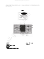
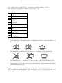
图解
A 燃烧器 H 指示灯 (用于电辐射)
B 烹饪支架 I 电辐射面板
C 控制旋钮 燃气灶/电热盘
D 燃气点火器
F 安全装置
-当火焰意外熄灭可立即切断煤气传输
All manuals and user guides at all-guides.com
all-guides.com

使用说明
在每个控制旋钮上都清晰标明燃气灶和电辐射灶相应的位置。
燃烧器
燃烧器分为不同尺寸和功率。烹饪时请选择直径和烹饪灶具最为接近的燃烧器。
烹饪时请使用旋钮上标注的火力控制火候:
关闭
高火
低火
点火时,先完全按住相应的旋钮,逆时针旋转至高火标记处,按住不放直到火苗持续点燃 2-3 秒钟后松开旋
钮,并打开安全装置“F”,确保自动供火。
打开燃气灶,将点燃的火柴或打火机靠近炉口,完全按住旋钮并逆时针旋转至高火处。
关闭燃气灶,顺时针旋转按钮至火焰熄灭。(应将旋钮设至“ ”处)
警告:如果在点火过程中,燃气意外泄漏,请立即关闭燃气控制旋钮,等待至少 1 分钟后再点火。
分离式双环火燃烧器
此燃烧器包含 2 个同中心的出火口,可以同时运作也可以分开独立供火。
同时使用双火烹饪,并将火力调至最大处,和使用常规灶相比,能大大缩短烹饪时间。
而且当使用双环火时,即使将火力调至最小处,灶口的皇冠式设计能将热量均匀地送至灶具底部。
各种大小的锅和盘都适用,如果用特别小的锅盘烹饪,我们建议您使用最中间的内焰燃烧器烹饪。
每一个“分离式双环火”都设有分开的独立控制旋钮。
旋钮上标注“ ”为外焰燃烧器;
旋钮上标注“ ”为内焰燃烧器。
要使用任一燃气器,请完全按住相应的旋钮,逆时针旋转至高火“ ”标记处。当按住旋钮时,燃烧器自
带的电子点火装置就会自动启动。
由于燃烧器带有安全装置“F”,在点燃火苗按住旋钮持续 2-3 秒钟后,该装置确保自动供火。
您可以选择一下相应旋钮选择常规的灶口烹饪:
Off
High
Low
All manuals and user guides at all-guides.com

关闭燃气灶,顺时针旋转按钮至火焰熄灭。(应将旋钮设至“ ”处)
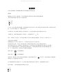
电辐射面板
炉灶面的玻璃下嵌入了双环热辐射元器件。您可以仅打开标有字母“A”的循环加热区域,或者同时打开标
有“A”和“B”的加热区域件以扩大烹饪的表面范围。打开“A”区域,只需简单地将旋钮顺时针方向调
至 12 种可用设置中任一一种您喜爱的方式。想增加“B”区域,请将旋钮设至“ ”处。然后继续将旋
钮逆时针方向调至 12 种中任一一种方式。
图示为加热区域,当启动加热时显示为红色。
A. 循环加热区域;
B. 延伸加热区域
C. 指示灯,当烹饪区域温度超过 60
o
C 时或关闭该加热区域时,该指示灯点亮。
当旋钮的设置位于任一非“关闭”的位置时,指示灯“H”持续点亮
All manuals and user guides at all-guides.com

保养方法
请在清洁和保养维修产品前,切断电源。
为了产品表面的美观和使用寿命,请务必经常仔细和彻底清洁产品,并且注意以下事项:
z 请不要使用蒸汽装置清洁产品。
z 产品的珐琅部分和玻璃表面,请用温水清洗,请不要使用带有研磨和腐蚀性的洗剂,以防止损坏产品;
z 燃气灶可拆移的部件请经常性用温水和温和洗剂清洗,确保将产品表面的烹饪残渣清洗干净;
z 请经常性仔细清洁灶炉面的自动点火装置和电子点火装置,并确保燃气出口通畅无阻碍;
z 如果长期使用含强石灰质的水和含磷的清洁剂清洁产品会造起不锈钢表面的损坏。建议您使用清水彻
底清洁这些部分,然后擦干。当烹饪时沾到食物,最好及时清理表面;
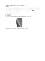
z 使用陶瓷玻璃面板前,必须保持表面干净,用湿布擦净灰尘及食物残渣。陶瓷玻璃表面必须用温水和
不带有研磨成分的洗剂清洗。定期使用特殊的产品专用洗剂清理陶瓷玻璃表面。当然首先,您可以使
用一种清洁铲清除所有表面的食物残留和油脂,例如 (非产品配件)(Fig.A).
在烹饪后灶台表面还有余热时,可以选用合适的清洗产品进行表面清洁(比如,您可以参考并选用默洛尼
家电售后中心提供的专用清洁产品)或是用纸和毛巾。用湿布擦净,然后擦干。像铝箔,塑料制品,或其
它合成材料制成的,还有糖份以及高糖含量的食物等一些易融的物质,若一旦表面粘附这些物质,请务必
在表面仍有余热时使用清洁铲立刻清理。使用特殊的产品专用清洁剂能在陶瓷玻璃表面形成透明的保护层,
防止灰尘和污垢积累。此保护层还能防止由于食物残留或高糖含量对陶瓷玻璃表面造成的损坏。在任何情
况下,请勿使用带有研磨成分的洗剂清洗。例如含强化学成分的刺激性洗剂,像烤箱清洁喷雾,强污清洁
剂(Fig.B);
灶口润滑
灶口由于长时间使用形成堵塞或变得难以旋转。如果这样,必须更换新灶头。
注意:灶头必须由专业人员才能更换。
使用方法
燃气灶使用方法
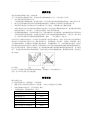
为了更好使用燃气灶,请您遵循一下使用指导:
z 根据不同灶口使用最合适的灶具(见表格),以防止火焰蔓延只灶具两侧;
z 请使用底部平坦的灶具,烹饪时请盖上锅盖;
z 当食物煮沸时,请将旋钮调至“低火”。
灶头类型 灶具直径(厘米)
半快速燃烧器(S) 16-20
辅助燃烧器 (A) 10-14
半鱼形燃烧器(SP) 16-20
三环火燃烧器(TC) 24-26
双环火双重调节(DCDR 内) 10-14
双环火双重调节(DCDR 外) 26-28
All manuals and user guides at all-guides.com

注意:当您使用直径小于 12CM 的灶具时,必须使用双环火双重调节(DCDR 内)进行烹饪。
若要了解更多有关灶头类型的信息,请参阅“灶头和灶口说明”一章。
电辐射灶使用方法
设置 热辐射灶
0 关闭
1 融化黄油和巧克力
2
3
加热液体
4
5
乳酪和酱汁
6
7
加热至沸点
8
9
烘烤
10
11
煮熟大块肉类
12 油炸
扩大加热区域
为了达到最佳烹饪效果,请遵循以下操作:
z 各种带盖的锅类都适用于陶瓷玻璃加热板面。必须确保锅底必须平整干净,通常砂锅的锅底较厚,比
较能均匀传递热量。
z 请使用锅底面积和加热区域面积最为贴合的锅进行烹饪,因为这样能充分吸收台面释放的热能。
z 请务必确保锅底平整干净,并确保锅底和灶面充分完好的接触。这样可以增强锅和灶面的使用寿命。
z 切勿使用在燃气灶上使用过的锅,因为烹饪时的热量会使锅底变形。这样在电辐射加热面板上继续使
用就难以达到最理想的烹饪效果。
注意:由于包装的原因,会有少许胶水在陶瓷玻璃表面留下痕迹。我们建议您在初次使用该陶瓷玻璃烹饪
时,用不含研磨质的清洁剂清理玻璃面板。在第一次使用的前几个小时里,您可能会发觉有橡胶味;请不
要担心,在使用一段时间后,橡胶味就会自然消失。
All manuals and user guides at all-guides.com

常见使用问题
遇到燃气灶不工作或无法正常工作,请先自查,如仍旧无法解决,请致电客服中心寻求帮助。
首先,检查是否有燃气中断或电源中断,尤其仔细检查,气阀是否松开。
遇到灶头无法点燃或火焰不均匀。
请检查:
z 灶头出火口没有堵塞;
z 灶上的所以可拆移的部件安装完好;
z 灶头周围没有气流。
带有安全装置的燃气灶,火苗不能持续点燃。
请检查:
z 打火时完全按住旋钮;
z 完全按住旋钮直到安全装置启动;
z 燃气口没有堵塞。
当设置至“低火”时,燃气熄灭。
请检查:
z 燃气口没有堵塞;
z 灶头周围没有气流;
z 最小火力值设置正确(请参阅“最小值调节”一章)
烹饪时灶具不平稳。
请检查:
z 灶具底部平整完好;
z 灶具按照灶头或电热盘中心摆放;
z 灶头支架没有倒置。
如果仔细作以上检查之后,燃气灶问题依旧,仍然无法正常工作,请致电最近的默洛尼家电客服中心,并
告知以下相关信息:
-故障类型
-质保卡上的产品代码的缩写等。
切勿让未经授权的维修商修理,并拒绝接受非原装配件。
安全使用
为了更安全更有效地使用我们的产品,请遵循如下建议:
z 若遇问题,请致电制造商授权许可的客服中心
z 请使用原装配件
z 此使用手册适用于 3 级嵌入式灶台。
z 本产品为非专业家用而设计,请勿对其进行功能技术改动。
z 使用手册仅适用于手册以及产品序列盘上标明的适用国家。
All manuals and user guides at all-guides.com
all-guides.com

z 本产品在正确按照使用手册正常接电的条件下,可保证使用安全。
为防止儿童接触和预防危险,请注意:
- 正确安放使用;
- 注意包装的安全存放(塑料包装袋,聚苯乙烯绝缘材料,钉子等);
- 注意陶瓷玻璃面板使用安全,通常在刚使用完至少一个半小时后,玻璃表面仍存高温;
- 若产品长时间不安装,请将含危险隐患的零部件妥善放置。
请避免以下情况:
- 用湿的身体部位接触产品;
- 赤脚时使用产品;
- 拖拉产品的电源插头;
- 不恰当/危险使用产品;
- 堵塞排气装置或散热孔;
- 插头接触燃气灶发热部件;
- 暴露在雨中或太阳下;
- 在周围使用易燃液体;
- 使用多头电源插头或延长电源线;
- 使用不平稳或易变形的灶具;
- 无灶具在铁架上时,将铁架留在陶瓷玻璃面板上;
- 将陶瓷玻璃面板当作操作台使用;
- 当有铝制品或塑料制品在陶瓷玻璃面板上时,打开热辐射装置;
- 用硬物或带尖头的物质撞击陶瓷玻璃面板;
- 当燃气灶口或电热盘还未冷却时关上玻璃盖;
- 在无专业人员的指导协助下,擅自安装或维修。
如遇以下情况,请寻求专业技术人员的帮助:
- 产品安装(参考制造商手册);
- 操作时遇到疑问;
- 由于插头不兼容而更换电流输出;
如遇以下问题,请联系制造商授权的客服中心:
- 当拆除产品包装后,对产品有疑问;
- 重置电源插头或遇危险时;
- 遇到产品不工作或故障时:要求使用原装零部件;
- 陶瓷玻璃面板遭到破坏时。
我们建议您遵循以下指导:
- 本产品仅供烹饪食物使用,切勿作其它用途;
- 拆除包装后,请立即检查产品及配件;
- 遇故障,清洁和维修前,请确保电源已经断开;
- 当不使用时,请断开电源开关,关闭燃气阀门;
- 断开电源,当陶瓷玻璃面板遭破坏时;
- 当不使用时,请经常检查燃气灶控制旋钮设置在“”/“”上;
- 当长时间不使用产品时,请拔掉电源插头;
- 对于不正确的安装或不正当不合理的使用,制造商有权不承担相应的责任风险。
All manuals and user guides at all-guides.com

嵌入式产品安装指导
以下指导经专业技术人员认可说明,请安装和维修时务必严格遵循。重要提示:在进行保养和常规维修之
前,请确保电源断开。
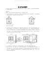
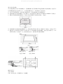
安置燃气灶
重要提示:燃气灶必须安置在永久通风的房间里,必须遵循以下要求:
a) 房间内必须配有适合尺寸的排风系统,将燃气时的烟雾和燃气排至室外。这就意味着,必须安装脱排油
烟机或电排风机,使其在每次烹饪食物时自动排气。
通过烟囱或分支烟道排气 直接排出室外
(燃气灶专用排气通道)
b) 房间必须有正常合适于燃烧的空气流入。燃烧所需空气流量应不少于 2m
3
/小时每千瓦的安装容量。空气
源可以直接通过一个至少 100cm
2
大小,内部交叉的管道由室外进入室内,并确保不会因意外而堵塞。
为了防止火焰可能意外窜出,这些未配有安全装置的器具必须开有 2 倍管道大小的通风口,即最小 200
cm
2
(Fig.A)。否则,房间的废气会通过邻近房间的排气通道排出室外(如上所述),当邻房并不是厨房,
如果是卧室就会有引起火灾的风险(Fig.B)。
细节 A 邻房 排气房
供燃气所需空气的通风孔示例 扩大窗口和地板间的通风口
Fig.A Fig.B
c) 为了加强和延长产品的使用寿命,最好额外加强通风,例如打开窗户或增强吸烟机的功率。
d) 液化气比空气重,所以一般向下沉淀。如果房间内使用液化气,必须合适地安装通往室外的通风口,以
防气体泄漏。所以,无论是空的或是半瓶满的液化气,都不能被安装或存放在室内或低于地面的空间(如
地下室等)。或是将液化气瓶单独放在房间内,但应确保附件没有热源(如烤箱,壁炉,火炉等),这些
都会瓶内的温度超过 50
o
C。
All manuals and user guides at all-guides.com

嵌入式炉灶的安装
该产品能安装在不高于炉架的橱柜中。直接接触燃气灶后的面板必须是由阻燃防火材料制成的。在使用中,
灶后面板的温度会达到 50
o
C 以上。为合理安装燃气灶台,必须预防以下情况发生:
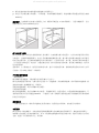
a) 炉灶可以安置在厨房,厨房-餐厅或起居室里,但切勿放置在卫生间或淋浴房。
b) 紧挨着燃气灶台的单独橱具(高于操作台)必须安置在高于操作台水平两侧至少 600mm 以上的地方。
c) 橱柜必须放置在脱排油烟机旁,高度至少在距离操作台 420mm 的地方。(Fig.C)
d) 若想将燃气灶直接安装在碗碟橱下方,必须安置在距离灶台面至少 700mm 以上的地方,如 Fig.C 所示。
e) 橱柜的尺寸必须参照本页最后 2 个图示的尺寸。固定随燃气灶提供的螺钉,将灶台置入操作台上,20~
40mm 的厚度(见 Fig.D)。为了更好的固定灶台,建议使用所有提供的螺钉。
螺钉位置用于 螺钉位置用于
高度=30mm 高度=40mm
螺钉位置用于
高度=20mm
注意:使用包含在“原装配件包”内的螺钉
All manuals and user guides at all-guides.com

f) 燃气灶能安装在带有制冷通风功能的嵌入式烤箱之上。
g) 若灶台不安装在嵌入式烤箱上,必须放置一块木质嵌板作绝缘用。此绝缘板必须放置在距离灶台底部
20mm 处。
重要提示:当安装燃气灶在嵌入式烤箱之上时,烤箱必须放置在 2 块木质条板上,当置入橱柜板后,记住
在板后留出至少 45 x 560mm 的空间。
燃气灶的燃气连接
燃气灶的燃气接入必须由专业经授权的人员来操作。在安装燃气接入的过程中,完全有必要选用经认可的
气阀龙头,它能很好地隔离燃气,也为今后的搬移或维修提供方便。接入燃气灶的燃气或液化气必须使用
经认可的合格气体,并且确认是能够适用的气体类型后,方可接入使用。若不是,请参照后面章节标题为
“不用类型气体的适用”的内容。当通过液化气瓶,接入使用液化气的时候,使用液压调解装置,使气体
符合使用标准。
重要事项:为了您的安全,使用符合标准的气体,延长产品的使用寿命,请确认您所使用的气体压力与所
示表格 1“管口和灶头特性”中的相符。
不可变形的管道连接
(铜管或钢管)
燃气和燃气灶的连接,不能对燃气灶的任何部分产生压力。
燃气灶的放置是可调节的,与燃气供应之间的“L”型连接器,其内部附带垫圈。若必须要转动连接器,就
要拿掉该垫圈(垫圈随燃气灶一同提供)
所提供的连接器是一端凸出带螺口的小钢管。
可变形的管道连接
燃气供给连接器是一端凸出带螺口的小钢管,可接圆形导管。使用导管时,必须按照标准将垫圈密封。可
变形的导管最大长度不得超过 2000mm。一旦连接了气体,请确保可变形的金属管不得接触任何可移动的部
件而且不得受挤压。
检查密封处
一旦燃气灶安装完毕,确认所以连接处已经妥善密封,使用肥皂水作测试。切勿使用火苗测试。
电源连接
燃气灶带有三极电源插头,交流电的使用规则是根据燃气灶底部标有的等级盘所示。接地电线为黄绿色。
如果嵌入式电烤箱上还要安装燃气灶,那 2 个电器的电源连接必须是互相独立的。这样不仅是出于安全的
考虑,更便于今后要移动其中之一或全部。
All manuals and user guides at all-guides.com

燃气灶台的电源连接
使用随燃气灶一起提供的电线配上标准插头,按照灶台底部的标识上的要求直接连接电源。放在电器和电
源间的单极开关在连接开口出至少留出 3mm(根据电源流通安全法则,接地的电线不能被开关阻断)。电 源
线必须妥善放置避免超过 50
o
C。
在正式连接前,请先确认以下事项:
z 保险丝和供电系统能承受产品所要求的承载负荷;
z 供电系统必须符合相关法律规定,配备安全有效的接地装置;
z 电源线和开关必须是处于可以接触调整的范围内。
重要提示:各种电线颜色表示如下:
绿色 黄色 -接地
蓝色 -地中线
棕色 -正极接地
有些电线不以颜色作为标识时,请按如下操作:
将绿色/黄色线和接线端标有“E”的电线(或绿色/黄绿色线)或 连接。
将棕色线和接线端标有“L”(或红色线)连接。
将蓝色线和接线端标有“N”(或黑色线)连接。
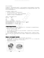
不同类型气体配合燃气灶的使用
为了使燃气灶能够使用不同种类的气体,根据每款设计不同,(型号请参阅粘于灶台底部的标签或包装),
一些燃气灶口必须作改装,方可适用,操作如下:
z 移开支架,将灶头转开灶台面;
z 使用 7mm 的螺丝刀拆下原灶喷口,换上适用于新气体的喷口。(请参阅所示表格 1“管口和灶头特性”)
z 将拆卸下的零部件收集起来;
z 在完成上述步骤后,使用客服中心提供的专用标识贴,改成新使用气体内容,并重新贴于灶台底部。
若所用气压与表中不符,必须在气体输出口安装气压调整器,该调整器必须符合本国规定的管道气体使用
标准。
替换独立式“双环火双重调节”灶头的喷口:
z 移开支架,将灶头转开灶台面。灶头分为两个独立的部分(Fig.E 和 Fig.F);
z 使用 7mm 的螺丝刀拆下原灶喷口。内焰灶有 1 个喷口,外焰灶有 2 个(同一大小)。换上适用于新气
体的新型号喷口。(请参阅所示表格 1“管口和灶头特性”)
z 将拆卸下的零部件收集起来。
All manuals and user guides at all-guides.com
all-guides.com

空气助燃规则
燃气灶无需额外的空气助燃。
最小值规则
z 将气阀调至最小
z 移动旋钮,顺时针调节调整器螺钮,直至火焰变小但正常燃烧。
注意:若使用液化气,常规螺钮必须完全钮上(顺时针)。
z 请确保,当旋钮快速从高调至低时,火焰没有熄灭。
z 当将供气值设置到最小时,若遇燃气灶上安全装置故障,请将调节器的螺钮调至较大值。(Fig.A-B)
一旦调解完毕,请在旧封印周围一圈涂上蜡(或其它适合材质)。
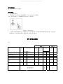
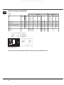
管口和灶头特性
表 1
液化气 天然气
热能功率 千瓦
(p.c.s.*)
流量*
g/h
灶头类型 直径
(毫
米)
额定. Ridot.
分流
1/100
(毫米)
喷头
1/100
(毫米)
*** ***
喷头
1/100
(毫米)
流量
*
l/h
半快速燃烧器(S) 75 1.90 0.40 30 70 138 136 106 181
辅助燃烧器(A) 55 1.00 0.40 30 50 73 71 79 95
三环火燃烧器(TC) 130 3.25 1.30 57 91 236 232 133 309
半鱼形燃烧器(SP) - 1.50 0.70 41 60 109 107 88 143
双环火双重调节(DCDR
内) 30 0.90 0.40 30 44 65 64 70 86
双环火双重调节(DCDR
外)2 喷头 130 4.10 1.30 57 70 298 293 114 390
额定值(mbar) 28-30 37 20
最小值(mbar) 20 25 17
供压
最大值(mbar) 35 45 25
All manuals and user guides at all-guides.com

* 15
o
C,1013mbar 气体条件下
** 丙烷气体 P.C.S.=50.37 MJ/kg
*** 丁烷气体 P.C.S.=49.47 MJ/kg
天然气 P.C.S.=37.78 MJ/m
3
本产品与欧盟标准相符:
- 73/23/EEC 19/08/73 (低伏特)和后来修订标准;
- 89/336/EEC 03/05/89(电磁兼容)和后来修订标准;
- 90/396/EEC 29/06/90(气体)和后来修订标准;
- 93/68/EEC 22/07/93 和后来修订标准。
All manuals and user guides at all-guides.com

HOB
PH 741 RQO CN
PH 741 RQO GH CN
Contents
Installation, 15-18
Positioning
Electrical connection
Gas connection
Data plate
Burner and nozzle specifications
Description of the appliance, 19
Overall view
Start-up and use, 20-21
Practical advice on using the burners
Practical advice on using the the Ceramic Glass
Module
Precautions and tips, 22
General safety
Disposal
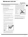
Maintenance and care, 23
Switching the appliance off
Cleaning the appliance
Gas tap maintenance
Troubleshooting, 24
Operating Instructions
English,14
CN
GB
GB
All manuals and user guides at all-guides.com

GB
15
Before operating your new appliance please read this
instruction booklet carefully. It contains important information
for safe use, installation and care of the appliance.
Please keep these operating instructions for future
reference. Pass them on to possible new owners of the
appliance.
Positioning
Keep packaging material out of the reach of children. It
can become a choking or suffocation hazard (see
Precautions and tips).
The appliance must be installed by a qualified professional
according to the instructions provided. Incorrect installation
may cause harm to people and animals or may damage
property.
This unit may be installed and used only in permanently
ventilated rooms in accordance with British Standard Codes
Of Practice: B.S. 6172 / B.S. 5440, Par. 2 and B.S. 6891
Current Editions. The following requirements must be
observed:
The room must be equipped with an air extraction system
that expels any combustion fumes. This may consist of a
hood or an electric fan that automatically starts each time
the appliance is switched on.
The room must also allow proper air circulation, as air is
needed for combustion to occur normally. The flow of air
must not be less than 2 m
3
/h per kW of installed power.
The air circulation system may
take air directly from the outside
by means of a pipe with an inner
cross section of at least 100 cm
2
;
the opening must not be
vulnerable to any type of
blockages.
The system can also provide the
air needed for combustion
indirectly, i.e. from adjacent rooms
fitted with air circulation tubes as
described above. However, these
rooms must not be communal
rooms, bedrooms or rooms that
may present a fire hazard.
Liquid petroleum gas sinks to the floor as it is heavier
than air. Therefore, rooms containing LPG cylinders must
also be equipped with vents to allow gas to escape in the
event of a leak. As a result LPG cylinders, whether
partially or completely full, must not be installed or stored
in rooms or storage areas that are below ground level
(cellars, etc.). It is advisable to keep only the cylinder
being used in the room, positioned so that it is not
subject to heat produced by external sources (ovens,
fireplaces, stoves, etc. ) which could raise the
temperature of the cylinder above 50°C.
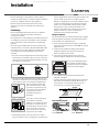
Fitting the appliance
Gas and mixed hobs are manufactured with type X degree
protection against overheating. The following precautions
must be taken when installing the hob:
Kitchen cabinets adjacent to the appliance and taller
than the top of the hob must be at least 600 mm from the
edge of the hob.
Hoods must be installed according to their relative
installation instruction manuals and at a minimum
distance of 650 mm from the hob.
Place the wall cabinets adjacent to the hood at a
minimum height of 420 mm from the hob (see figure).
If the hob is installed beneath a
wall cabinet, the latter must be
situated at a minimum of 700 mm
above the hob (see figure).
The installation cavity should have the dimensions
indicated in the figure.
Fastening hooks are provided, allowing you to fasten the
hob to tops that are between 20 and 40 mm thick. To
ensure the hob is securely fastened to the top, we
recommend you use all the hooks provided.
555 mm
55 mm
475 mm
Hook fastening diagram
Hooking position Hooking position
for top H=20 mm for top H=30 mm
Installation
Enlarging the ventilation slot
between window and floor.
Adjacent
Room
Room to be
Vented
A
Examples of ventilation holes
for comburant air.
In a chimney stack or branched flue.
(exclusively for cooking appliances)
Directly to
the Outside
600mm min.
540mm min.
700mm min.
All manuals and user guides at all-guides.com

GB
16
Front
Hooking position Back
for top H=40 mm
Use the hooks contained in the accessory pack
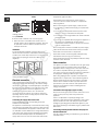
Where the hob is not installed over a built-in oven, a
wooden panel must be installed as insulation. This must
be placed at a minimum distance of 20 mm from the
lower part of the hob.
Ventilation
To ensure adequate ventilation, the back panel of the
cabinet must be removed. It is advisable to install the oven
so that it rests on two strips of wood, or on a completely flat
surface with an opening of at least 45 x 560 mm (see
diagrams).
! The hob can only be installed above built-in ovens with a
cooling ventilation system.
Electrical connection
Hobs equipped with a three-pole power supply cable are
designed to operate with alternating current at the voltage
and frequency indicated on the data plate (this is located on
the lower part of the appliance). The earth wire in the cable
has a green and yellow cover. If the appliance is to be
installed above a built-in electric oven, the electrical
connection of the hob and the oven must be carried out
separately, both for electrical safety purposes and to make
extracting the oven easier.
Connecting the supply cable to the mains
Install a standardised plug corresponding to the load
indicated on the data plate.
The appliance must be directly connected to the mains using
an omnipolar circuit-breaker with a minimum contact opening
of 3 mm installed between the appliance and the mains. The
circuit-breaker must be suitable for the charge indicated and
must comply with current electrical regulations (the earthing
wire must not be interrupted by the circuit-breaker). The
supply cable must not come into contact with surfaces with
temperatures higher than 50°C.
The installer must ensure that the correct electrical
connection has been made and that it is compliant with
safety regulations.
Before connecting to the power supply, make sure that:
The appliance is earthed and the plug is compliant with
the law.
The socket can withstand the maximum power of the
appliance, which is indicated on the data plate.
The voltage is in the range between the values indicated
on the data plate.
The socket is compatible with the plug of the appliance. If
the socket is incompatible with the plug, ask an
authorised technician to replace it. Do not use extension
cords or multiple sockets.
Once the appliance has been installed, the power supply
cable and the electrical socket must be easily accessible.
The cable must not be bent or compressed.
The cable must be checked regularly and replaced by
authorised technicians only (see Assistance).
The manufacturer declines any liability should these safety
measures not be observed.
Gas connection
The appliance should be connected to the main gas supply
or to a gas cylinder in compliance with current national
regulations. Before carrying out the connection, make sure
the cooker is compatible with the gas supply you wish to
use. If this is not the case, follow the instructions indicated in
the paragraph Adapting to different types of gas.
When using liquid gas from a cylinder, install a pressure
regulator which complies with current national regulations.
Check that the pressure of the gas supply is consistent
with the values indicated in Table 1 (Burner and nozzle
specifications). This will ensure the safe operation and
longevity of your appliance while maintaining efficient
energy consumption.
Connection with a rigid pipe (copper or steel)
Connection to the gas system must be carried out in such
a way as not to place any strain of any kind on the
appliance.
There is an adjustable L-shaped pipe fitting on the
appliance supply ramp and this is fitted with a seal in order
to prevent leaks. The seal must always be replaced after
rotating the pipe fitting (seal provided with appliance). The
gas supply pipe fitting is a threaded 1/2 gas cylindrical male
attachment.
Connecting a flexible jointless stainless steel pipe to a
threaded attachment
The gas supply pipe fitting is a threaded 1/2 gas cylindrical
male attachment.
560 mm.
45 mm.
All manuals and user guides at all-guides.com
all-guides.com

GB
17
These pipes must be installed so that they are never longer
than 2000 mm when fully extended. Once connection has
been carried out, make sure that the flexible metal pipe
does not touch any moving parts and is not compressed.
Only use pipes and seals that comply with current national
regulations.
Checking the tightness of the connection
When the installation process is complete, check the pipe
fittings for leaks using a soapy solution. Never use a flame.
Adapting to different types of gas
To adapt the hob to a different type of gas other than default
type (indicated on the rating plate at the base of the hob or
on the packaging), the burner nozzles should be replaced
as follows:
1. Remove the hob grids and slide the burners off their
seats.
2. Unscrew the nozzles using a 7 mm socket spanner, and
replace them with nozzles for the new type of gas (see
table 1 Burner and nozzle characteristics).
3. Reassemble the parts following the above procedure in
the reverse order.
4. Once this procedure is finished, replace the old rating
sticker with one indicating the new type of gas used.
Sticker are available from any of our Service Centres.
Replacing the nozzles on separate double flame
burners:
1. remove the grids and slide the burners from their
housings. The burner consists of 2 separate parts (see
figure);
2. unscrew the burers with a 7 mm wrench spanner. The
internal burner has a nozzle, the external burner has two
(of the same size). Replace the nozzle with models suited
to the new type of gas (see table 1).
3. replace all the components by repeating the steps in
reverse order.
Adjusting the burners primary air :
Does not require adjusting.
Setting the burners to minimum:
1. Turn the tap to the low flame position.
2. Remove the knob and adjust
the adjustment screw, which is
positioned in or next to the tap pin,
until the flame is small but steady.
3. Having adjusted the flame to the required low setting,
while the burner is alight, quickly change the position of
the knob from minimum to maximum and vice versa
several times, checking that the flame does not go out.
4. Some appliances have a safety device (thermocouple)
fitted. If the device fails to work when the burners are set
to the low flame setting, increase this low flame setting
using the adjusting screw.
5. Once the adjustment has been made, replace the seals
on the by-passes using sealing wax or a similar
substance.
If the appliance is connected to liquid gas, the regulation
screw must be fastened as tightly as possible.
Once this procedure is finished, replace the old rating
sticker with one indicating the new type of gas used.
Stickers are available from any of our Service Centres.
Should the gas pressure used be different (or vary slightly)
from the recommended pressure, a suitable pressure
regulator must be fitted to the inlet pipe (in order to comply
with current national regulations).
DATA PLATE
Electrical
connections
voltage of 220-240V ~ 50/60Hz
voltage of 220-230V ~ 50/60Hz
maximum power absorbed 2000W
(see data plate )
This appliance conforms to the
following European Economic
Community directives:
-73/23/EEC dated 19/02/73 (Low
Voltage) and subsequent
amendments
- 89/336/EEC dated 03/05/89
(Electromagnetic Compatibility)
and subsequent amendments
- 93/68/EEC dated 22/07/93 and
subsequent amendments.
- 90/336/EEC dated 29/06/90 (Gas)
and subsequent amendments.
- 2002/96/EC
All manuals and user guides at all-guides.com

GB
18
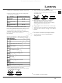
Burner and nozzle specifications
Table 1
Liquid Gas Natural Gas
Burner Diameter
(mm)
Thermal
power
kW
(p.c.s.*
Thermal
power
kW
(p.c.s.*)
By-Pass
1/100
Nozzle
1/100
Flow*
g/h
Thermal
power
kW
(p.c.s.*)
Nozzle
1/100
Flow*
l/h
Ridot. Nomin. (mm) (mm) *** ** Nomin. (mm)
Semi Fast (S) 75 0,40 1,90 30 70 138 136 1,90 106 181
Auxiliary (A) 55 0,40 1,00 30 50 73 71 1,00 79 95
Double flame (DCDR internal) 30 0,40 0,90 30 44 65 64 0,90 74 86
Double flame (DCDR external)
2 nozzle
130 1,30 4,10 57 70 298 293 4,10 110 390
Supply
Pressures
Nominal (mbar)
Minimum (mbar)
Maximum (mbar)
28-30
20
35
37
25
45
20
17
25
* At 15°C and 1013 mbar - dry gas
** Propane P.C.S. = 50.37 MJ/Kg
*** Butane P.C.S. = 49.47 MJ/Kg
Natural P.C.S. = 37.78 MJ/m
3
DC
S
A
DC TC
PH 741 RQO CN
PH 741 RQO GH CN
The hob can only be installed above built-in ovens with a cooling ventilation system.
All manuals and user guides at all-guides.com

GB
19
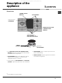
Description of the
appliance
Overall view
SAFETY
DEVICES*
Ignition for
GAS BURNERS*
*
Only available on certain models.
The INDICATOR LIGHT FOR CERAMIC GLASS
MODULE switches on whenever the selector knob
is moved from the off position.
GAS BURNERS differ in size and power. Use the
diameter of the cookware to choose the most
appropriate burner to cook with.
Control Knobs for GAS BURNERS and ELECTRIC
PLATES* adjust the power or the size of the flame.
GAS BURNER ignition* enables a specific burner
to be lit automatically.
SAFETY DEVICE* stops the gas flow if the flame is
accidentally extinguished.
GAS BURNERS
Support Grid for
COOKWARE
INDICATOR LIGHT FOR
CERAMIC GLASS
MODULE*
CERAMIC GLASS
MODULE*
Control Knobs for
GAS BURNERS and
ELECTRIC HOTPLATES*
All manuals and user guides at all-guides.com

GB
20
The position of the corresponding gas burner or
electric hotplate* is shown on every knob.
Gas burners
Each burner can be adjusted to one of the following
settings using the corresponding control knob:
Off
Maximum
Minimum
To light one of the burners, hold a lit match or lighter
near the burner and, at the same time, press down
and turn the corresponding knob anti-clockwise to the
maximum setting.
Since the burner is fitted with a safety device, the
knob should be pressed for approximately 2-3
seconds to allow the automatic device keeping the
flame alight to heat up.
When using models with an ignition button, light the
desired burner pressing down the corresponding
knob as far as possible and turning it anticlockwise
towards the maximum setting.
If a flame is accidentally extinguished, turn off the
control knob and wait for at least 1 minute before
trying to relight it.
To switch off the burner, turn the knob in a clockwise
direction until it stops (when reaches the position).
The separate double flame burner*
This burner consists of two concentric burners which
can operate either together or separately.
Use of the double flame on the maximum setting gives
a very high power which reduces cooking times with
respect to conventional burners.
Moreover the double flame crown provides a more
uniform distribution of heat on the bottom of the pan,
when using both burners on minimum.
To ensure that the double-flame burner is used to its
full potential, never set the inside ring to minimum and
the outside ring to maximum at the same time.
Pots and pans of all sizes can be used. In the case of
the smaller pots and pans we recommend the use of
only the internal burner.
There is a separate control knob for each of the
separate double flame burners.
The knob marked by the symbol
operates the
external burner;
The knob marked by the symbol
operates the
internal burner.
To turn on one of the rings, press the relative knob in
all the way and turn it anti-clockwise to the high
setting
. The burner is fitted with an electronic
igniter that automatically starts when the knob is
pressed in.
Since the burner is equipped with a safety device,
after lighting the burner keep the knob pressed in for
about 2-3 seconds to allow the device which keeps
the flame lit automatically to heat up.
The selected burner can be regulated using the
corresponding knob, as follows:
Off
Maximum
Minimum
To switch off the burner, turn the knob in a clockwise
direction until it stops (when reaches the position).
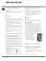
Ceramic Glass Module*
This cooktop is fitted with dual-ring radiant heating
elements located beneath the glass. It is possible to
turn on only the circular part of the elemement
(identified by the letter "A") or the cooking surface can
be enlarged by turning on both "A" and "B". To turn
only the circular "A" element, simply turn the knob in
the clockwise direction to any one of the 12 available
settings. To add the "B" section, turn the knob to
setting 12 and then click it into the
setting. Then
proceed by turning the knob in the counter-clockwise
direction to one of the 12 settings.
The figure shows the heating
zones, which become red when
the element is turned on.
A. Circular heating zone;
B. Extended heating zone;
C.Indicator light to show when
the cooking zone is above
60°C, even after the heating
element has been turned off.
When the knob is on any of the settings other than
"Off", the Indicator Light for Ceramic Glass Module
comes on.
Practical advice on using the burners
To ensure the burners operate efficiently:
Use appropriate cookware for each burner (see
table) so that the flames do not extend beyond the
bottom of the cookware.
Start-up and use
*
Only available on certain models.
A
C
B
All manuals and user guides at all-guides.com
ページが読み込まれています...
ページが読み込まれています...
ページが読み込まれています...
ページが読み込まれています...
-
 1
1
-
 2
2
-
 3
3
-
 4
4
-
 5
5
-
 6
6
-
 7
7
-
 8
8
-
 9
9
-
 10
10
-
 11
11
-
 12
12
-
 13
13
-
 14
14
-
 15
15
-
 16
16
-
 17
17
-
 18
18
-
 19
19
-
 20
20
-
 21
21
-
 22
22
-
 23
23
-
 24
24


Ariston PH 741 RQO GH CN Operating Instructions Manual
- カテゴリー
- ホブ
- タイプ
- Operating Instructions Manual
他の言語で
- English: Ariston PH 741 RQO GH CN
その他のドキュメント
-
ROSIERES JZT-RGV63WFM PN ユーザーマニュアル
-
Bosch PRA3A6D71T/46 取扱説明書
-
-
-
Siemens ER3A6BB70X/37 ユーザーマニュアル
-
-
APRILIA SCARABEO 250 I.E. - 2006 ユーザーマニュアル
-
APRILIA SCARABEO 200 ユーザーマニュアル
-
Sanus CFR115 ユーザーマニュアル
-
Electrolux EKG9686X ユーザーマニュアル