
E5000 STANDARD
Tuned Propulsion System
多旋翼动力系统
V1.0
2016.12
User Manual
用户手册

©
2016 DJI All Rights Reserved.
3
EN
Disclaimer
Thank you for purchasing the E5000 Standard Tuned Propulsion
System (hereinafter referred to as “product”). Read this
disclaimer carefully before using this product. By using this
product, you hereby agree to this disclaimer and signify that
you have read it fully. Please install and use this product in
strict accordance with the User Manual. SZ DJI TECHNOLOGY
CO., LTD. and its affiliated companies assume no liability for
damage(s) or injuries incurred directly or indirectly from using,
installing or retting this product improperly, including but not
limited to using non-designated accessories.
DJI
TM
is a trademark of SZ DJI TECHNOLOGY CO., LTD. (abbreviated
as “DJI”) and its afliated companies. Names of products, brands,
etc., appearing in this manual are trademarks or registered
trademarks of their respective owner companies. This product and
manual are copyrighted by DJI with all rights reserved. No part of this
product or manual shall be reproduced in any form without the prior
written consent of or authorization from DJI.
This disclaimer is produced in various languages. In the event of
variance among different versions, the Chinese version shall prevail
when the product in question is purchased in China, and the English
version shall prevail when the product in question is purchased in
any other region.
Legend
Important
Warning
When powered on, the motors and propellers will rotate
very quickly and can cause serious damage or injuries
if used improperly. Always maintain caution and make
safety your top priority.
The E5000 Standard generates powerful thrust. Be
sure to operate it with caution to avoid potential safety
risks. DO NOT use the E5000 Standard if you are not an
experienced user or you are under the age of 18.
AGES

4
©
2016 DJI All Rights Reserved.
EN
1. The maximum allowable voltage of the E5000 Standard is
52.2 V. Operate with care.
2. Always fly your aircraft in areas free of people, animals,
power lines, and other obstacles.
3. DO NOT approach or touch the motors or propellers when
the unit is powered on.
4. Before takeoff, ensure that the propellers and motors are
installed correctly and the propellers are unfolded.
5. Ensure that all parts of the aircraft are in good condition. DO NOT
y with worn or damaged parts.
6. Ensure that all parts are firmly in place and all screws are
tight before each ight.
7. Only use compatible, authorized DJI parts.
Introduction
The E5000 Standard Tuned Propulsion System is designed for
multirotor aircraft with a payload of 4.5 - 7.0 kg/rotor. Water-
proof and dust-proof features (the 1280S ESC is IP66 rated and
IEC 60529 compliant) allow the system to be washed, making it
ideal for industrial applications and professional photography in
demanding environments.
The brand new M10 motor features an integrated centrifugal
cooling system and annular array of cooling fins to enhance
heat dissipation. A lighter M10 Air motor is also designed for
selection. Reinforced blades and a perfected aerodynamic
design minimize rotational inertia on the foldable 28-inch Z-Blade
propellers to equip large platforms with sharp response.
The 1280S ESC uses FOC (Field-Oriented Control) algorithms
to allow for more motor responsiveness and precision control.
Additional protection functions extend the life of the ESC. When
used with the DJI N3 or A3 ight controllers, the ESC data cable
handles communication with the ight controller and also acts
as a backup throttle signal transmission cable for increased
reliability and a safer ight.
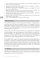
1. Parts
Foldable Propellers (CW or CCW, accessories included), Motor
(accessories included), ESC and other items can be purchased
separately on the DJI Online Store.

©
2016 DJI All Rights Reserved.
5
EN
M10 Motor M10 Air Motor
2880 Foldable Propeller
(Clockwise)
2880 Foldable Propeller
(Counterclockwise)
1280S ESC Updater
Smart ESC Communication Cable
Motor Accessories:
Motor Screws (M4×16 Hex Socket)
Propeller Adapter Screws
(M3×11 Hex Cap)
Propeller Accessories:
Propeller Adapter Screws
(M3×11 Hex Cap)
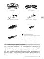
2. Flight Controller Settings
The E5000 ESC features a DJI optimized FOC algorithm to
offer improved performance during rotor acceleration and
deceleration. The gain values and power bandwidth must be
adjusted according to your ight control system and airframe.
The table below shows typical parameters when using the E5000
Standard with a DJI A3 ight control system, a six-rotor frame
with a diagonal distance of 1600 mm, and at a takeoff weight of
35 kg:

6
©
2016 DJI All Rights Reserved.
EN
Basic Gain Sensitivity Gain
Power Bandwidth
Pitch Roll Yaw Throttle Brake Attitude
110% 110% 100% 100% 50% 100% 80%
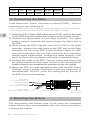
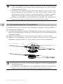
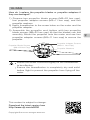
3. Connecting the ESCs
Tools Required: Power distribution board (PDB)*, electric
soldering iron and soldering tin
* Use a PDB which has sufcient trace spacing and current capacity,
according to the number of ESCs and the battery voltage.
1) Solder the ESC’s black GND cable and red VCC cable to the pads
on the PDB. Ensure that there are no open circuits or short circuits.
2) Connect the signal cable to your ight controller. The signal
cable’s red wire transmits the control signal; the black wire is
for GND.
3) When using the ESC together with the DJI N3 or A3 flight
controller, connect the data cable to the iESC port on the ight
controller via the smart ESC communication cable for real-
time communication with the ight controller and redundant
throttle signal transmission. Arrange the cable properly if not
used, so that it will not interfere with other on-board devices.
4) Connect the motor to the ESC. Test the motors and ensure that
the rotation direction of each motor is correct. You can reverse the
rotation direction by swapping the positions of any two cables.
5) Mount the ESC at a well-ventilated place with the ESC Status
Indicator clearly visible. Placement under the frame arm is
recommended. DO NOT cover the cooling ns on the top of
the ESC to avoid overheating.
Data Cable
(For communication &
rmware update)
Signal Cable
(To the ight controller)
ESC Status Indicator Three-phase
Motor Cables
Power Cables
(Red, VCC; Black, GND)
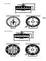
4. Mounting the Motors
The dimensions and thread sizes of the motor are illustrated
below. Ensure they are compatible with your frame arm before
mounting the motors.

©
2016 DJI All Rights Reserved.
7
EN
M10 Motor
M10 Air Motor
Ø 8 mm
Ø 26 mm
Ø 107 mm
34 mm
57 mm
Ø 8 mm
Ø 26 mm
Ø 107 mm
36.5 mm
59.5 mm
Ø 36 mm
4×M3 Thread Depth 6 mm
Ø 66 mm
4×M4 Thread Depth 20 mm
Ø 36 mm
4×M3 Thread Depth 6 mm
Ø 66 mm
4×M4 Thread Depth 20 mm

8
©
2016 DJI All Rights Reserved.
EN
Use a suitable motor mounting plate and airframe that
can withstand the large thrust delivered by the E5000
Propulsion System.
Choose the appropriate screw length and screw size
according to the depth of the assembly hole and
thickness of the motor mounting plate. Using screws
that are too long or too large may damage the motor.
When mounting or removing the motors, be careful to
prevent foreign articles from entering the motor.
5. Assembling the Propellers
Threadlocker and a wrench for propeller adapter screws (M3×11
hex cap) are required.
1) Pair the propellers marked CW with the clockwise rotating motors;
pair the propellers marked CCW with the counterclockwise
rotating motors.
2) Apply threadlocker to the four screw holes on the motor.
3) Mount the propeller onto the motor, and use four propeller
adapter screws (M3×11 hex cap) to secure the propeller.
Ensure the screw is secured tightly for the threadlocker
to be effective.
Ensure the threadlocker is completely dry and solid before
ight to prevent the propeller from ying off the motor.
Propeller Adapter Screws
(M3×11 Hex Cap)
CW or CCW Mark

©
2016 DJI All Rights Reserved.
9
EN
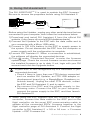
ESC Updater Computer
Before using the Updater, unplug any other serial devices that are
connected to your computer, then follow the instructions below:
1) Download and install DJI Assistant 2 from the official DJI
website. (http://www.dji.com/e5000/info#downloads)
2) Connect the Updater to the ESC with the data cable and to
your computer with a Micro USB cable.
3) Connect a 12S LiPo battery to the ESC to supply power to
the system. Do not disconnect the ESC from the computer or
power supply until the conguration is complete.
4) Launch DJI Assistant 2. When a connection is established,
the software will display the connected devices.
5) Click
under “Connected Devices” to enter the firmware
update page. Check the current rmware version and ensure
the installed rmware is up to date. If not, login with your DJI
account and click the Upgrade button.
If your ESC is not recognized by DJI Assistant 2 (no
connected devices):
Check if there is more than one FTDI device connected
such as another DJI Updater, an FTDI USB adapter or
development board (e.g. a BeagleBone, Raspberry or
Arduino board). Unplug the other FTDI devices, restart
the ESC and DJI Assistant 2, and try again.
Re-connect the ESC and the power supply in the
following order: Connect the ESC to your computer,
connect the power supply to the ESC, and then launch
DJI Assistant 2.
※ When using the ESC together with the DJI N3 or A3 flight
controller, connect the data cable to the iESC port on the
flight controller via the smart ESC communication cable to
update all the connected ESCs' firmware together in the
flight controller page of DJI Assistant 2: Connect the flight
controller to DJI Assistant 2 -> N3 or A3 icon -> Firmware
Update -> ESC Firmware List.
6. Using DJI Assistant 2
The DJI ASSISTANT
TM
2 is used to update the ESC rmware.
※
Be sure to remove the propellers before using DJI Assistant 2.

EN
EN
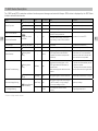
7. ESC Status Description
The 1280S smart ESC’s protection and alarm functions prevent damage and extend its lifespan. ESCs status is displayed by the ESC Status
Indicator and notication sounds.
Status LED Sound ESC Output Cause Resolution
Normal Operation
Slow Pulsing Green 1356 Normal System Ready /
Solid Green / Normal Motor Started /
Solid Yellow / Normal Motors are rotating at full throttle. /
Open-circuit Protection
Blinking Red, Yellow
and Green
/ Stop
Motor phase break or abnormal connection
with the ESC when powered on.
Fix problem then restart ESC.
Short-circuit Protection
Motor cable short-circuiting, ESC output
short-circuiting, or short-circuit inside the
ESC.
Stall Protection
Blinking Red Rapidly / Stop Motor Stalled Fix problem then restart ESC.
Overheated Protection
Blinks Red Twice / Normal ESC internal temperature > 100℃. ESC internal temperature < 80℃.
Throttle Backup*
Blinking Yellow
Slowly
/ Normal
Main throttle signal lost during ight, i.e.
the ESC signal cable is disconnected.
The system will switch to backup throttle
automatically.
The aircraft can y with the backup
throttle. However, it is recommended
to land the aircraft and re-connect the
signal cable as soon as possible.
* DJI N3 or A3 ight controller required
Abnormal Throttle Warning
Blinking Yellow
Slowly
Slow Beep Stop
1. Both the main throttle and backup throttle
signal were lost during ight, i.e. the
ESC signal cable and data cable are
disconnected.
2. Main throttle signal lost before the motor
started.
1. Land the aircraft immediately and re-
connect the cables.
2. The system will not switch to backup
throttle. Re-connect the signal cable.
Blinking Yellow
Rapidly
Single Beep Stop Starting input signal is not at the minimum. Throttle input is smaller than 1120
μs
.
Abnormal Voltage Warning
Blinking Red and
Yellow Alternately
Double Beep Stop
Starting input voltage is out of the range of
the 12S LiPo battery, i.e. input voltage >
52.2 V or input voltage < 43.2 V.
Adjust input voltage.
Low Voltage Warning / Normal
Input voltage lower than 42 V when
operating.
Voltage higher than 43.2 V.

12
©
2016 DJI All Rights Reserved.
EN
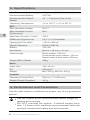
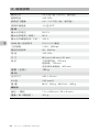
8. Specications
Max Thrust 14 kg/rotor (44.4 V, Sea Level)
Recommended Battery 12S LiPo
Recommended Takeoff
Weight
4.5 - 7.0 kg/rotor (Sea Level)
Operating Temperature 14° to 122° F (-10° to 50° C)
ESC
Max Allowable Voltage 52.2 V
Max Allowable Current
(Continuous)
80 A
Max Peak Current (< 3 sec) 120 A
PWM Input Signal Level 3.3 V / 5 V Compatible
Operating Pulse Width 1120 to 1920 μs
Signal Frequency 30 Hz to 500 Hz
Battery 12S LiPo
Dimensions 86 mm × 46 mm × 21 mm
Cable Length Power cables: 720 mm
Three-phase motor cables: 150 mm
Signal cable & data cable: 900 mm
Weight (With Cables) 189 g
Motor
Stator Size 100×10 mm
KV 120 rpm/V
Weight M10: 520 g, M10 Air: 420 g
Propeller
Diameter×Thread Pitch 28×8 in (711×203 mm)
Weight (Single Propeller) 161 g
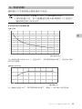
9. Performance and Parameters
Use the data below to facilitate the proper use of the propulsion
system.
Use the system at the recommended takeoff weight for
optimal performance.
DO NOT overload the system. A takeoff weight more
than 1.2 times of the maximum recommended value will
severely compromise safety and performance.

©
2016 DJI All Rights Reserved.
13
EN
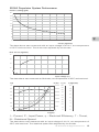
E5000 Propulsion System Performance
0
2
4
6
8
10
12
14
16
20
18
2 4 6 8 10 12 14 16
Power Loading (g/W)
Thrust (kg/rotor)
The data above was measured with an input voltage of 44.4 V, at a temperature
of 25°C and sea level. The thrust was adjusted by the throttle.
15
12
13
14
0 40 42 44 46 48 50 52 54
Max Thrust (kg/rotor)
Input Voltage (V)
The data above was measured at full throttle, at a temperature of 25°C and sea level.
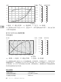
I – Current, P – Input Power, η – Electrical Efciency, T – Thrust,
N – Rotational Speed
The data above was measured with an input voltage of 44.4 V, at a temperature of
25°C and sea level. The rotational speed was adjusted by the throttle.
I (A)
0
500
1500
2500
3500
1000
2000
3000
0
60
50
40
30
20
10
70
80
90
100
P (W)
T (kg/rotor)
0
2
4
6
8
10
16
14
12
1000 1500 25002000 3000 3500 45004000
T
P
η
I
N (rpm)
10
20
30
40
50
60
70
0
η
(%)

14
©
2016 DJI All Rights Reserved.
EN
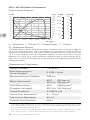
M10 / M10 Air Motor Performance
Performance Diagram
η – Efciency, I – Current, P – Output Power, Τ – Torque,
N – Rotational Speed
The data above contain theoretical values measured with an input voltage of
44.4 V, for reference only. When operating at a temperature of 25°C with no
additional cooling devices, the motor cannot operate with a current more than
70 A. It can support short term operation (about 10 to 30 sec) with a current
between 40 A and 70 A, and continuous operation with a current under 40 A.
The motor run time should depend on the actual environmental temperature and
cooling conditions.
Characteristic Parameters
Speed Constant 120 rpm/V
Back-Electromotive
Force Constant*
0.0796 V·s/rad
Mechanical Time Constant 288 ms
Motor Rotor Inertia
M10: 302 kg·mm
2
M10 Air: 208 kg·mm
2
Total Rotor Inertia
(Propeller Included)
M10: 3408 kg·mm
2
M10 Air: 3314 kg·mm
2
Torque Constant* 0.0790 N·m/A
Line-to-Line Inductance** 41 - 50 μH
Line-to-Line Resistance 60 mΩ
Thermal Time Constant 600 s
*
The Back-Electromotive Force Constant and Torque Constant may vary
when the motor current is strong. The values provided mainly apply to when
the motor current is under 20 A.
** The Line-to-Line Inductance was measured with a current frequency of 1 kHz
in an RLC circuit. It varies periodically as a function of the rotor position.
T
I (A)
η
(%)
0 1000 2000 3000 4000 5000 6000
N (rpm)
10
20
30
40
50
60
70
80
90
100
0
50
150
250
300
350
400
450
200
500
100
P (W)
0
1000
2000
2500
500
1500
3000
P
I
η
0
5
10
15
20
25
35
30
(N·m)
T

EN
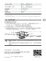
10. FAQ
How do I replace the propeller blades or propeller adapters if
they are damaged?
1) Prepare two propeller blade screws (M6×22 hex cap),
four propeller adapter screws (M3×11 hex cap), and four
propeller washers.
2) Apply threadlocker to the screw holes on the motor and the
propeller adapter.
3) Assemble the propeller and tighten with two propeller
blade screws (M6×22 hex cap) so that the blades can fold
smoothly. Mount the propeller onto the motor and use four
propeller adapter screws (M3×11 hex cap) to secure the
propeller.
Propeller Adapter Screws
(M3×11 Hex Cap)
Propeller Blade Screws
(M6×22 Hex Cap)
Propeller Washers
Ensure the screw is secured tightly for the threadlocker
to be effective.
Ensure the threadlocker is completely dry and solid
before ight to prevent the propeller from ying off the
motor.
This content is subject to change.
Download the latest version from
http://www.dji.com/e5000
Copyright ©
2016 DJI All Rights Reserved.

16
©
2016
大疆创新 版权所有
CH
免责声明
感谢您购买 E5000 标准版。在使用之前,请仔细阅读本声明,一
旦使用,即被视为对本声明全部内容的认可和接受。请严格遵守手
册安装和使用该产品。因用户不当使用、安装、改装(包括使用非
DJI 指定的零配件,如:电机、电调、螺旋桨等)造成的任何损失,
深圳市大疆创新科技有限公司及其关联公司将不承担任何责任。
DJI
TM
是深圳市大疆创新科技有限公司及其关联公司的商标。本文
出现的产品名称、品牌等,均为其所属公司的商标或注册商标。
本产品及手册为深圳市大疆创新科技有限公司版权所有。未经许
可,不得以任何形式复制翻印。
关于不同语言版本的免责声明可能存在的语义差异,中国以中文
版为准,其他地区以英文版为准。
符号说明
重要注意事项
年 龄
产品使用注意事项
若使用不当,高速旋转的螺旋桨可能会对人身财产造成严
重伤害和破坏。因此在使用时,请务必注意安全。
E5000 标准版拉力较大,为避免潜在的安全风险,务必
谨慎操作。非专业用户及未满 18 岁的人士请勿使用。
1. E5000 标准版最大允许电压高达 52.2 V,务必遵守相关安全规
范进行操作。
2. 使用时请远离不安全因素,如障碍物、人群、高压线等。
3. 切勿贴近或接触旋转中的电机或螺旋桨,避免被旋转中的螺旋
桨割伤。
4. 使用前请检查螺旋桨和电机是否安装正确,折叠桨是否已展开。
5. 使用前请检查各零部件是否完好。如有部件老化或损坏,请更
换新部件。
6. 每次飞行前,检查飞行器各部分结构及螺丝是否松动。
7. 请使用 DJI 提供的零配件。

©
2016
大疆创新 版权所有
17
CH
简 介
E5000 标准版是一款单轴负载 4.5 - 7.0 kg 的多旋翼动力系统,适
合行业应用及专业航拍,全系统可进行冲洗维护(其中 1280S 电
调防尘防水等级可达 IP66,参照 IEC 60529 标准)。M10 电机配
备上升式离心风冷系统,配合中心环形散热阵列,全面提升冷却
效率;用户亦可选用轻量级的 M10 Air 电机。Z-Blade 28 寸折叠
桨采用新一代翼型和优秀的气动设计,低惯量特性有效帮助大型
机架保持灵敏控制。1280S 智能电调采用磁场定向控制(FOC,
Field-Oriented Control)算法,实现精准敏捷的电机驱动控制;
主动保护功能可延长使用寿命;适配 DJI N3 及 A3 飞控系统,特
有的数据线可实现与飞控的实时通信及备份油门信号的传输。
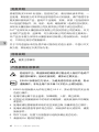
1. 相关物品
E5000 标准版的电机(含配件)、螺旋桨(含 CW 或 CCW 桨一
只以及配件)、电调等物品均为独立包装,用户可分别购买。
M10 电机 M10 Air 电机
2880 可折叠螺旋桨(CW) 2880 可折叠螺旋桨(CCW)
升级器1280S 电调

18
©
2016
大疆创新 版权所有
CH
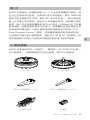
智能电调通信转接线
电机配件:
电机固定螺丝
(M4×16,内六角)
桨夹螺丝(M3×11,外六角)
螺旋桨配件:
桨夹螺丝(M3×11,外六角)
2. 飞控参数调节
E5000 动力系统电调采用 DJI 优化的 FOC 算法,提升了加减速性
能。使用前,用户需要根据所使用的机架及飞控系统适当调节感
度参数及动力带宽。下表是配合 A3 飞控系统和轴距为 1600 mm
的六轴机架使用,起飞重量为 35 kg 时的一组典型参数:
基础感度 灵敏感度
动力带宽
俯仰 横滚 航向 油门 刹车 姿态
110% 110% 100% 100% 50% 100% 80%
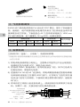
3. 安装电调
工具和材料(自备):分电板 *、电烙铁和焊锡
* 根据实际使用电调数量及电池电压选择具备安全布线间距和足够通流能
力的分电板
1) 将电调电源线焊到分电板上,注意焊点牢固并且不会出现短路。
电源线红色为电源 VCC,黑色为地 GND。
2) 将电调 PWM(脉宽调制)信号线连接至飞控。其中红色线为
控制信号线,黑色线为地线。
3) 若使用 DJI N3 或 A3 飞控系统,将电调数据线通过智能电调通
信转接线连接至主控器的 iESC 接口,可实现与飞控的实时通
信及油门信号冗余传输。不使用时请注意将线材收好,避免影
响飞行。
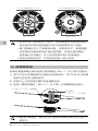
4) 将电机的三根线分别连到电调上。调试使电机按照需求方向旋
转。如果不一致,交换该电机的任意两根连线。
电调数据线
( 用于通信及固件升级 )
电调 PWM 信号线
( 连接至飞控 )
电调状态指示灯 三相电机线
电源线 (红色,
VCC;黑色,GND)

©
2016
大疆创新 版权所有
19
CH
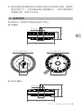
4. 安装电机
参考电机尺寸将电机安装到合适的力臂上。
M10 电机
Ø 8 mm
Ø 26 mm
Ø 107 mm
36.5 mm
59.5 mm
Ø 36 mm
4×M3 螺纹深度 6 mm
Ø 66 mm
4×M4 螺纹深度 20 mm
M10 Air 电机
Ø 8 mm
Ø 26 mm
Ø 107 mm
34 mm
57 mm
5) 将电调固定至通风良好且电调状态指示灯明显的位置,推荐安
装至机臂下方。切勿遮挡电调正面的散热片,否则可能导致电
调温度过高,影响飞行安全。

20
©
2016
大疆创新 版权所有
CH
E5000 动力系统的拉力较大,务必确保您所选用的电机
固定座及机架的结构强度与动力系统提供的拉力匹配。
请注意螺纹孔尺寸和螺纹深度。安装电机时,请根据螺
纹深度和您使用的电机固定座厚度,选择合适的螺丝。
若使用过长的螺丝,拧入后可能损坏电机内部结构。
安装及拆卸电机时,切勿使异物进入电机内部。
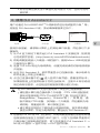
5. 安装螺旋桨
安装时请自备螺丝胶和适用于桨夹螺丝(M3×11,外六角)的扳手。
1) 带 CW 标记的螺旋桨对应顺时针旋转电机,带 CCW 标记的螺
旋桨对应逆时针旋转电机。
2) 在电机上方的安装孔螺纹内使用螺丝胶。
3) 使用 4 颗桨夹螺丝(M3×11,外六角)安装螺旋桨至电机。
桨夹螺丝
(M3×11,外六角)
CW 或 CCW 标记
Ø 36 mm
4×M3 螺纹深度 6 mm
Ø 66 mm
4×M4 螺纹深度 20 mm
确保拧紧螺丝。螺丝过松可能会导致螺丝胶无法完全干
燥固化。

©
2016
大疆创新 版权所有
21
CH
务必在螺丝胶完全干燥固化后再进行飞行,否则可能导
致射桨。
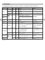
6. 使用 DJI Assistant 2
用户可通过 DJI ASSISTANT
TM
2 调参软件进行电调固件升级
※
等。
连接至 DJI Assistant 2 前,务必确保螺旋桨已拆下。
使用升级器前,请移除计算机上的其他串口设备,然后按以下步
骤操作:
1) 从 DJI 官方网站下载并运行 DJI Assistant 2 安装程序 , 按照提
示完成软件安装。(http://www.dji.com/e5000/info#downloads)
2) 将电调数据线接入升级器一端的接口,使用 Micro USB 线连接
升级器与计算机。
3) 连接 12S LiPo 电池为电调供电,设置完成前请勿切断电源或断
开连接。
4) 运行 DJI Assistant 2。软件界面显示已连接设备,表示电调与
软件连接上并能正常通信。
5) 点击已连接设备中的
进入固件升级界面,查看固件版本。
如果服务器上的固件较新于您的当前版本,注册 DJI 帐号或使
用已有帐号登录,点击相应的链接按照提示进行升级。
若 DJI Assistant 2 无法识别电调(未显示已连接设备):
请检查计算机是否接有多个升级器、FTDI USB 适配器或
其他可能使用到 FTDI 芯片组的开发工具(包括但不限于:
BeagleBone、Raspberry、Arduino 等)。如果是,请
断开其他 FTDI 设备,仅保留一个升级器,然后重新为电
调供电,再重启软件,即可恢复正常。
请注意是否按照以下顺序进行连接和供电:首先将电调连
接至计算机,然后为电调供电,最后运行 DJI Assistant 2。
※ 若使用 DJI N3 或 A3 飞控系统,将电调数据线通过智能电调通
信转接线连接至主控器的 iESC 接口,可在飞控调参界面同时
升级所有已连接电调的固件:将飞控连接至 DJI Assistant 2 ->
N3 或 A3 图标 -> 固件升级 -> ESC 固件列表。
电调 升级器 计算机

CH
CH
7. 电调工作状态描述
1280S 智能电调具备主动保护及报警功能,可减少电调损坏,延长使用寿命。用户可通过电调状态指示灯或提示音了解电调工作状态。
工作状态 指示灯 提示音 电调输出 触发的条件 解除的条件
正常工作
绿灯呼吸点亮 1356 正常 系统就绪 /
绿灯常亮 / 正常 电机已启动 /
黄灯常亮 / 正常 满油门旋转 /
断路保护
红黄绿灯
交替闪烁
/ 关闭
上电时电机相线断路、与电调连线异常
修复后重启电调
短路保护
上电时电机相线短路、电调输出短路、电调内部
短路
堵转保护
红灯快闪 / 关闭 电机堵转 修复后重启电调
过温报警
红灯双闪 / 正常 电调内部温度超过 100℃ 电调内部温度低于 80℃
油门备份 *
黄灯慢闪 / 正常
飞行过程中主油门丢失,即电调 PWM 信号线连
接断开,自动切换至备份油门
使用备份油门可以正常飞行至降落,
但仍建议用户尽快降落并重新连接
PWM 信号线
油门异常报警
黄灯慢闪 B---B… 关闭
1. 飞行过程中主油门及备份油门均丢失,即电调
PWM 信号线和数据线均断开
2. 电机未启动时主油门丢失
1. 立即降落并重新连线
2. 此时不可切换至备份油门,请重
新连线
黄灯快闪 BBB… 关闭 上电时油门不在最小值 油门恢复到 1120 μs 以下
电压异常保护
红黄灯交替闪烁
BB---BB… 关闭
上电时输入电压不在 12S 锂电池正常工作范围
内,即大于 52.2 V 或小于 43.2 V
调整输入电压
低电压报警 / 正常 运行过程中输入电压低于 42 V 电压恢复至 43.2 V 以上
* 需配合 DJI N3 / A3 飞控
ページが読み込まれています...
ページが読み込まれています...
ページが読み込まれています...
ページが読み込まれています...
ページが読み込まれています...
ページが読み込まれています...
ページが読み込まれています...
-
 1
1
-
 2
2
-
 3
3
-
 4
4
-
 5
5
-
 6
6
-
 7
7
-
 8
8
-
 9
9
-
 10
10
-
 11
11
-
 12
12
-
 13
13
-
 14
14
-
 15
15
-
 16
16
-
 17
17
-
 18
18
-
 19
19
-
 20
20
-
 21
21
-
 22
22
-
 23
23
-
 24
24
-
 25
25
-
 26
26
-
 27
27


