
V1.4 2016.12
E2000 PRO
用户手册
User Manual
多旋翼动力系统
Tuned Propulsion System


©
2016 DJI All Rights Reserved.
3
EN
Disclaimer
Thank you for purchasing the E2000 Pro Tuned Propulsion System
(hereinafter referred to as “product”). Read this disclaimer carefully before
using this product. By using this product, you hereby agree to this disclaimer
and signify that you have read it fully. Please install and use this product in
strict accordance with the User Manual. SZ DJI TECHNOLOGY CO., LTD.
and its affiliated companies assume no liability for damage(s) or injuries
incurred directly or indirectly from using, installing or retting this product
improperly, including but not limited to using non-designated accessories.
DJI
TM
is a trademark of SZ DJI TECHNOLOGY CO., LTD. (abbreviated
as “DJI”). Names of products, brands, etc., appearing in this manual are
trademarks or registered trademarks of their respective owner companies.
This product and manual are copyrighted by DJI with all rights reserved. No
part of this product or manual shall be reproduced in any form without prior
written consent of or authorization from DJI.
This disclaimer is produced in various languages. In the event of variance
among different versions, the Chinese version shall prevail when the product
in question is purchased in Mainland China, and the English version shall
prevail when the product in question is purchased in any other region.
Warning
When powered on, the motors and propellers will rotate very quickly
and can cause serious damage or injuries. Always be vigilant and make
safety your top priority.
1. The allowable voltage of the E2000 Pro can reach 52.2 V. Be sure to
use it in strict accordance with the related safety rules.
2. Always attempt to fly your aircraft in areas free of people, animals,
power lines, and other obstacles.
3. DO NOT approach or touch the motors or propellers when the unit is
powered on.
4. Ensure that there are no open circuits or short circuits when soldering
the power cables.
5. Before takeoff, ensure that the propellers and motors are installed
correctly and the propellers are unfolded.
6. Ensure that all parts of the aircraft are in good condition. DO NOT y
with worn or damaged parts.
7. Ensure that all parts are rmly in place and all screws are tight before
each ight.
8. Only use compatible, authorized DJI parts.
Legend
Important Hints and Tips
Instruction
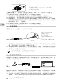
The E2000 Pro Tuned Propulsion System is a multirotor propulsion
system designed for multirotor aircraft with a payload of 1.8 - 2.5 kg/
rotor. It is ideal for industrial applications and professional photography
in rugged environments.
The new design of the powertrain provides effective protection for internal

4
©
2016 DJI All Rights Reserved.
EN
components while making assembly and conguration more convenient.
A brand new motor uses a centrifugal fan to improve heat dissipation.
Its airtight structure keeps out liquid and foreign objects, protecting the
inner parts of the motor against dust and liquid corrosion.
Reinforced blades and the perfect aerodynamic design give the Z-Blade
21-inch foldable propellers ultra-high strength and rigidity.
The Smart ESC uses a sinusoidal drive powered by advanced algorithms
to allow for a responsive motor drive with precise control. Like most
DJI products, the ESC firmware can be updated to ensure optimal
performance for the E2000 Pro.
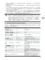
1. Parts
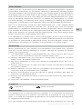
The Powertrain (CW or CCW, screws included) and Updater can be
purchased separately on the DJI Online Store.
Updater
Powertrain (Clockwise) Powertrain (Counterclockwise)
Arm Screws (M3×10 Hex)
Anti-rotation Screws (M3×6.5 Hex)
ESC Board Screws (M2×4)
Motor Screws (M3×8 Thumb)
ESC Cover Screws (M2.5×6)
Propeller Blade Screws (M4×13.3 Hex)
Propeller Cover Screws (M3×9 Hex)
Propeller Washers, Propeller Lockrings
Screw Pack:
2. Gain Value Settings
The E2000 Pro ESC features a sinusoidal drive, replacing the traditional
square-wave drive, to offer improved performance during rotor acceleration
and deceleration.
To achieve the same sensitivity as square-wave-driven ESCs, the gain
values must be reduced according to your flight control system and
airframe. The table below shows typical gain values when using the
E2000 Pro with a DJI A2 ight control system, a six-rotor frame with a
diagonal distance of 1100 mm, and at a takeoff weight of 14 kg:
Basic Gain Attitude Gain
Pitch Roll Yaw Pitch Roll Vertical
130% 130% 100% 150% 150% 100%
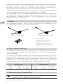
3. Mounting the Powertrains
Use a suitable airframe that can withstand the large thrust
delivered by the E2000 Propulsion System.

©
2016 DJI All Rights Reserved.
5
EN
Arm Screws (M3×10 Hex)
ESC Status Indicator
Tools Required
:
M3 hex key
1) Loosen the two arm screws (M3×10 hex) on the powertrain arm.
2) Pull the cables of the powertrain through the frame arm. Then insert
the frame arm into the powertrain arm.
3) Align the components so that the propeller is oriented upright after
assembly.
4) OPTIONAL: Use an anti-rotation screw (included) and M3×6.5 hex
screw holding base customized to the tube used (not included) or
rivet (not included) to secure the position of the powertrain arm to
achieve optimal performance.
5) Tighten the two screws (M3×10 hex) on the powertrain arm.
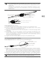
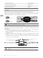
4. Connecting the Cables
Tools Required: Electric soldering iron and soldering tin
JST 3-pin Cable
(To the Updater)
Power Cables
Signal Cable
(To the ight controller)
1) Solder the power cables of each powertrain to the frame’ s power system.
Make sure that the solder points are strong and that there is no chance
for a short circuit. The red cable should be attached to the positive
terminal and the black cable should be attached to the negative terminal.
2) Connect the signal cable to your ight controller. The signal cable’s
orange wire transmits the control signal; the brown wire is for ground.
Make sure there are no short circuits or open circuits.
Motor
Powertrain Arm
Mounting Hole
(
3.2 mm)
Built-in ESC
CW or CCW Mark
Propeller
The powertrains are compatible with frame arms with an outer
diameter of 28 mm. Mount the powertrains to appropriate frame
arms only.
Identify the clockwise and counter-clockwise marks on the
propellers and mount the powertrains onto the corresponding
frame arms.

6
©
2016 DJI All Rights Reserved.
EN
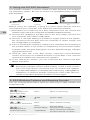
5. Using the DJI ESC Assistant
The DJI ESC Assistant is used to update the ESC rmware and congure
the propulsion system. Be sure to remove the propellers before using the
ESC Assistant.
Powertrain Updater PC
Before using the Updater, unplug any other serial devices that are
connected to your computer, then follow the instructions below:
1) Download and install the DJI ESC Assistant from the official DJI
website (http://www.dji.com/product/e2000/info#downloads).
2) Connect the Updater to the ESC with a JST 3-pin cable; connect it to
your computer with a Micro USB cable.
3) Connect a 12S LiPo battery to the ESC to supply power to the system.
Do not disconnect the ESC from the computer or power supply until
the conguration is complete.
4) Launch the DJI ESC Assistant. Observe the indicators at the bottom of
the window. When a connection is established, the Connection Status
Indicator (left) will glow solid green and the Data Exchange Indicator
(right) will blink blue.
5) Click the ‘View’ tab. In the ‘ESC’ section, check the current rmware
version and ensure the installed rmware is up-to-date. If not, click the
hyperlink and follow the instructions to update it.
6) In the ‘LED Color’ section, you can customize the colors of the ESC
Status Indicators.
If the ESC is not recognized by the DJI ESC Assistant (the Data
Exchange Indicator remains inactive blue), check if there is more
than one FTDI device connected such as another DJI Updater,
an FTDI USB adapter or development board (e.g. a BeagleBone,
Raspberry or Arduino board). Unplug the other FTDI devices,
restart the DJI ESC Assistant and ESC, and try again.
6. ESC Blinking Patterns and Beeping Sounds
You can instantly tell the ESC’s status by observing the LED indicator and
emitted sounds.
LED Indicator Sound Description
Blinking Yellow and
Green alternately
None Motor is connecting.
/
Breathing Red or
breathing Green
1356 System ready.
— / —
Solid Red or solid Green
None Motor started normally.
Blinking Red and
Yellow alternately
None
Double Beep
Self-test failed.
Abnormal input voltage.
Triple Beep
Motor parameters and ESC
rmware data do not match.

©
2016 DJI All Rights Reserved.
7
EN
Blinking Yellow rapidly
Single Beep
Starting input signal is not at
minimum. Check the settings of
your ight controller, receiver
and remote controller.
Blinking Yellow slowly
Slow Beep
No signal input.
— Solid Yellow None Motors are rotating at full throttle.
Blinking Red rapidly
None
Motor stalled and ESC locked.
Land your aircraft immediately,
stop the motors, and power it
off. Then check if the motors are
damaged.
×2
Blinks Red twice
None
ESC high temperature (above
100°C). Land your aircraft
immediately and power it off.
Wait for the ESC to cool down to
room temperature.
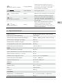
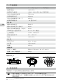
7. Specications
Max Thrust 5100 g/rotor (50 V, Sea Level)
Recommended Battery 12S LiPo
Recommended Takeoff Weight 1800 - 2500 g/rotor (Sea Level)
Powertrain Weight (Single) 430 g
Powertrain Cable Length 750 mm
Compatible Frame Arm Outer Diameter
28 mm
Operating Temperature -10° to 50° C
ESC
Max Allowable Voltage 52.2 V
Max Allowable Current (Continuous) 25 A
Max Peak Current (< 3 sec) 40 A
PWM Input Signal Level 3.3 V / 5 V Compatible
Operating Pulse Width 1120 - 1920 μs
Signal Frequency 30 Hz to 450 Hz
Battery 12S LiPo
Motor
Stator Size 60 × 10 mm
KV 130 rpm/V
Weight 230 g
Propeller
Diameter × Thread Pitch 21 × 7 inch (533 × 178 mm)
Weight (Single Propeller) 58 g

8
©
2016 DJI All Rights Reserved.
EN
Motor Dimensions
22 mm
2 × M3 Thread depth 5.5 mm
4 × M3 Thread depth 8 mm
30 mm
43.4 mm
29.2 mm
66.7 mm
6 mm
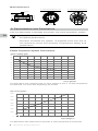
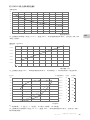
8. Performance and Parameters
Use the data below to facilitate the proper use of the propulsion system.
A payload less than half of the maximum thrust is recommended
for optimal performance.
DO NOT overload the system. A payload more then 2/3 of
the maximum thrust will severely compromise safety and
performance.
E2000 Propulsion System Performance
2
4
6
8
10
12
14
16
18
20
0
Power Loading (g/W)
Thrust (g/rotor)
500 1000 1500 2000 2500 3000 3500 4000 4500
The data above was measured with an input voltage of 44.4 V, at room temperature
and sea level. The thrust was adjusted by the throttle.
2500
3000
3500
4000
4500
5000
5500
380 40 42 44 46 48 50 52 54
Max Thrust (g/rotor)
Input Voltage (V)
The data above was measured at full throttle, at room temperature and sea level.

©
2016 DJI All Rights Reserved.
9
EN
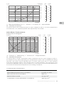
η – Electrical Efciency, T – Thrust, I – Current, P – Input Power,
N – Rotational Speed
The data above was measured with an input voltage of 44.4 V, at room temperature
and sea level. The rotational speed was adjusted by the throttle.
Τ – Torque, η – Efciency, I – Current, P – Output Power,
N – Rotational Speed
The data above contain theoretical values measured with an input voltage of 44.4 V,
for reference only. When operating at a temperature of 25℃ with no additional cooling
devices, the motor cannot operate with a current more than 20 A. It can support
short term operation (about 10 to 30 sec) with a current between 15 A and 20 A, and
continuous operation with a current under 15 A. The motor run time should depend on
the actual environmental temperature and cooling conditions.
Characteristic Parameters
Speed Constant 130 rpm/V
Back-Electromotive Force Constant 0.0734 V·s/rad
Mechanical Time Constant 200 ms
Motor Rotor Inertia 70 kg·mm
2
Total Rotor Inertia (Propeller Included) 700 kg·mm
2
6010 Motor Performance
Performance Diagram
1000 2000 3000 4000 50000
T
I
P
η
10
20
30
40
50
60
70
80
90
η
(%)
N (rpm)
T (g/rotor)
0
500
1000
1500
2000
2500
3000
3500
4000
4500
I (A)
0
2
4
6
8
10
12
14
16
P (W)
0
100
200
300
400
500
600
700
(N·m)
1
0
2
3
4
5
6
7
8
9
10
1000 2000 3000 4000 5000 6000 7000
0
10
20
30
40
50
60
70
80
90
100
η
(%)
I
P
η
N (rpm)
I (A)
0
50
100
150
200
250
P (W)
0
20
400
600
800
1000
1200
T
T

10
©
2016 DJI All Rights Reserved.
EN
Propeller Cover Screws
(M3×9 Hex)
Propeller Blade Screws
(M4×13.3 Hex)
Propeller Washers
Ensure the screw is secured tightly for the threadlocker to be
effective.
9. FAQ
How do I check if the propellers are secure and will not y off?
Make sure you check the marks on the screws and cover on the propeller
before each flight. If the propeller is loose, the marks will not line up,
indicating that the screws should be tightened.
If the two propeller blade screws are swapped or other screws are
used, the marks may not be accurate.
How do I replace the propeller blades or propeller covers if they are
damaged?
1) Prepare two propeller blade screws (M4×13.3 hex), two propeller
cover screws (M3×9 hex), and four propeller washers.
2) Apply threadlocker to the two screw holes on the motor and the
propeller cover.
3) Assemble the propeller and tighten with two propeller blade screws
(M4x13.3 hex) so that the blades can fold smoothly. Mount the
propeller onto the motor and use two propeller cover screws (M3×9
hex) to secure the propeller.
Torque Constant 0.076 N·m/A
Line-to-Line Inductance 0.224 mH
Line-to-Line Resistance 230 mΩ
Thermal Constant 600 s

EN
Copyright
©
2016 DJI All Rights Reserved.
The content is subject to change.
Download the latest version from
http://www.dji.com/product/e2000
If you have any questions about this document, please contact
DJI by sending a message to
.
Compliance Information
FCC Compliance
This device complies with Part 15 of the FCC Rules. Operation is subject
to the following two conditions: (1) This device may not cause harmful
interference, and (2) This device must accept any interference received,
including interference that may cause undesired operation.
Any changes or modifications not expressly approved by the party
responsible for compliance could void the user’s authority to operate the
equipment.
EU Compliance Statement
SZ DJI TECHNOLOGY CO., LTD. hereby declares that this device is in
compliance with the essential requirements and other relevant provisions
of the EMC Directive.
A copy of the EU Declaration of Conformity is available online at
www.dji.com/euro-compliance
EU contact address: DJI GmbH, Industrie Strasse. 12, 97618, Niederlauer, Germany
Manufactured by:
14th oor, West Wing, Skyworth Semiconductor Design Building NO.18 Gaoxin South
4th Ave, Nanshan District, Shenzhen, Guangdong, China
DJI Support
www.dji.com/support

12
©
2016
大疆创新 版权所有
CH
免责声明
感谢您购买 E2000 专业版。在使用之前,请仔细阅读本声明,一旦使用,
即被视为对本声明全部内容的认可和接受。请严格按照手册安装和使
用该产品。因用户不当使用、安装、改装(包括使用非指定的 DJI
TM
零配件如:电机、电调、螺旋桨等)造成的任何损失,深圳市大疆创
新科技有限公司及其关联公司将不承担任何责任。
DJI 是深圳市大疆创新科技有限公司所有的商标。本文出现的产品名
称、品牌等,均为其所属公司的商标或注册商标。本产品及手册为深
圳市大疆创新科技有限公司版权所有。未经许可,不得以任何形式复
制翻印。
关于不同语言版本的免责声明可能存在的语义差异,中国大陆地区以
中文版为准,其他地区以英文版为准。
产品使用注意事项
高速旋转的螺旋桨可能会对人身财产造成一定程度的伤害和破坏,因
此在使用 E2000 专业版时,请务必注意安全。
1. E2000 专业版最大允许电压高达 52.2 V,务必遵守相关安全规范
进行操作。
2. 使用时请远离不安全因素,如障碍物、人群、高压线等。
3. 切勿贴近或接触旋转中的电机或螺旋桨,避免被旋转中的螺旋桨
割伤。
4. 确保电源线焊接正确,电路无短路、无开路。
5. 使用前请检查螺旋桨和电机是否安装正确,折叠桨是否已展开。
6. 使用前请检查各零部件是否完好。如有部件老化或损坏,请更换新
部件。
7. 每次飞行前,检查飞行器各部分结构及螺丝是否松动。
8. 请使用 DJI 提供的零配件。
符号说明
重要注意事项
操作、使用提示
简 介
E2000 专业版是一款单轴负载 1.8 - 2.5 kg 的多旋翼动力系统,适合
行业应用及专业航拍。一体式动力总成,全面保护内部元件,安装调
试简单快捷。全新电机配备离心风扇,提供强效冷却;封闭式结构设计,
有效阻止异物进入及液体腐蚀。Z-Blade 21 寸折叠桨采用最新一代翼
型和优秀的气动设计,提供充足的结构强度和刚度。正弦驱动的智能
电调搭载先进专利算法,实现精准敏捷的电机驱动控制;固件支持用
户自行升级,方便用户享受未来的新功能。

©
2016
大疆创新 版权所有
13
CH
1. 相关物品
E2000 专业版的动力总成(CW 或 CCW,附带螺丝包)、升级器均
为单个独立包装,用户需分别购买。
2. 感度参数调节
E2000 专业版配备全新电调,使用正弦驱动代替传统的方波驱动,提
升了加减速性能。使用前,用户需要根据所使用的机架及飞控系统适
当降低感度参数。下表是配合 DJI A2 飞控系统和轴距为 1100 mm 的
六轴机架使用,起飞重量为 14 kg 时的一组典型参数:
基本感度 姿态感度
俯仰 横滚 航向 俯仰 横滚 垂直
130% 130% 100% 150% 150% 100%
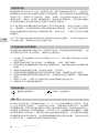
3. 安装动力总成
E2000 动力系统的拉力较大,务必确保您所选用机架的结
构强度与动力系统提供的拉力匹配。
动力总成适用于外径 28 mm 的碳管,请安装至符合规格的
碳管上。
安装时,请注意区分螺旋桨上的 CW 或 CCW 标记,将其安
装到对应的机臂碳管上。
动力总成 (CW) 动力总成 (CCW)
力臂固定螺丝(M3×10,内六角)
力臂防旋螺丝(M3×6.5,内六角)
电调固定螺丝(M2×4)
电调保护盖螺丝(M2.5×6)
电机固定螺丝(M3×8,大头)
桨叶螺丝(M4×13.3,内六角)
桨盖螺丝(M3×9),螺旋桨垫片,螺旋桨防松圈
螺丝包
升级器
CW 或 CCW 标记
安装孔(
3.2 mm)
电机
力臂接头
内置电调
螺旋桨

14
©
2016
大疆创新 版权所有
CH
工具(自备):适用于力臂固定螺丝(M3×10,内六角)的扳手
1) 拧松动力总成上的两颗 M3×10 力臂固定螺丝。
2) 将动力总成的四根线穿过碳管,然后将碳管插入力臂接头中。
3) 旋转碳管,保证其安装至机架后动力总成的螺旋桨朝向正上方。
4) 根据需要,在安装孔处使用力臂防旋螺丝(M3×6.5 内六角,需按
照所用碳管自行定制内衬)或合适的铆钉锁住碳管,以防动力总成
转动影响飞行。(选装)
5) 拧紧动力总成上的两颗 M3×10 力臂固定螺丝。
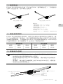
4. 系统连线
工具和材料(自备):电烙铁和焊锡
JST 3 针线
(用于电调固件升级)
电源线
(红色正极,黑色负极)
电调 PWM 信号线
(连接至飞控)
1) 将电源线焊到您机架的电源系统上,注意焊点牢固并且不会出现短
路。电源线红色为正极,黑色为负极。
2) 将电调 PWM(脉宽调制)信号线连接至飞控。其中橙色线为控制
信号线,棕色线为地线。
请确保电路中没有短路或开路。
5. 使用电调助手
电调助手主要用于电调固件升级、系统配置等。连接电调助手前,务
必确保螺旋桨已拆下。
ESC 升级器 计算机
使用升级器前,请移除计算机上的其他串口设备,然后按照以下步骤
操作:
1) 从 DJI 官方网站下载并运行电调助手安装程序,按照提示完成软件
安装。(http://www.dji.com/cn/product/e2000/info#downloads)
力臂固定螺丝(M3×10,内六角)
电调状态指示灯

©
2016
大疆创新 版权所有
15
CH
2) 将动力总成的 JST 3 针线接入升级器,使用 Micro USB 线连接升
级器与计算机。
3) 连接 12S LiPo 电池为内置电调供电,设置完成前请勿切断电源或
断开连接。
4) 运行电调助手并等待动力总成的内置电调与软件连接。PC 连接指
示灯(左)绿灯常亮,通信指示灯(右)蓝灯闪烁,表示电调与软
件连接上并能正常通信。
5) 单击“查看”选项卡,在“ESC”界面中查看固件版本,如果服务器
上的固件较新于您的当前版本,点击相应的链接按照提示进行升级。
6) 在“LED 颜色”界面设置电调状态指示灯颜色。
若电调助手无法识别电调(软件界面左下角绿灯常亮,蓝灯
熄灭),请检查计算机是否接有多个 DJI 升级器、FTDI USB
适配器或其他可能使用到 FTDI 芯片组的开发工具(包括但不
限 于:BeagleBone、Raspberry、Arduino 等)。如果是,
请断开其他 FTDI 设备,仅保留一个 DJI 升级器,然后重启电
调助手,重新为电调供电,即可恢复正常。
6. 电调状态指示灯及提示音描述
使用时,请根据电调状态指示灯及鸣音判断产品是否正常工作。如果
出现异常,请排查故障。
指示灯状态 提示音 描述
黄绿灯交替闪烁
无 识别电机
/
红灯或绿灯呼吸点亮
1356 就绪
— /
—
红灯或绿灯常亮
无 电机正常启动
红黄灯交替闪烁
无 上电自检未通过
BB--BB
…
上电时输入电压异常
BBB--BBB
…
识别的电机参数与固件存储不
匹配
黄灯快闪 BBBB
…
上电时输入油门量不在最小
值,请检查主控、接收机或遥
控器设置
黄灯慢闪 B--B--B
…
无信号输入
—
黄灯常亮 无 满油门旋转
红灯快闪 无
电机堵转,电调已锁死
请立即降落飞行器关闭电机并
断开电源,然后检查电机是否
受损
×2 红灯双闪 无
电调温度过高(超过 100℃)
请立即降落飞行器关闭电机并
断开电源,等待电调冷却

16
©
2016
大疆创新 版权所有
CH
7. 产品规格
最大拉力 5100 克 / 轴(50 V,海平面)
推荐电池 12S LiPo
推荐起飞重量 1800 - 2500 克 / 轴(海平面)
动力总成线组长度 750 mm
适用碳管外径 28 mm
动力总成重量(单个) 430 g
使用环境温度 -10 至 50℃
电 调
最大允许电压 52.2 V
最大允许电流(持续) 25 A
最大允许峰值电流(3 秒) 40 A
PWM 输入信号电平 3.3 V / 5 V 兼容
工作脉宽 1120 - 1920
μ
s
兼容信号频率 30 - 450 Hz
电池 12S LiPo
电 机
定子尺寸 60×10 mm
KV 值 130 rpm/V
重量 230 g
螺旋桨
直径 × 螺距 533×178 mm(21×7 inch)
重量(单个螺旋桨) 58 g
电机尺寸
8. 性能参数
请根据以下性能参数合理使用动力系统。
建议载重小于最大拉力的一半,以获得最佳性能。
请勿超重飞行,载重超过最大拉力的 2/3 会严重影响性能以
及安全性。
22 mm
2×M3 螺纹深度 5.5 mm
4×M3 螺纹深度 8 mm
30 mm
43.4 mm
29.2 mm
66.7 mm
6 mm

©
2016
大疆创新 版权所有
17
CH
E2000 动力系统性能
0
2
4
6
8
10
12
14
16
18
20
力效 (g/W)
拉力 (g/rotor)
500 1000 1500 2000 2500 3000 3500 4000 4500
以上数据为电调输入电压 44.4 V、室温 25℃、海平面高度的环境下,变化油门输入调
节拉力测得。
2500
3000
3500
4000
4500
5000
5500
380 40 42 44 46 48 50 52 54
最大拉力(g/rotor)
输入电压(V)
以上数据为室温 25℃、海平面高度的环境下,电调满油门,调节电调输入电压测得。
1000 2000 3000 4000 50000
T
I
P
η
10
20
30
40
50
60
70
80
90
η
(%)
N (rpm)
T (g/rotor)
0
500
1000
1500
2000
2500
3000
3500
4000
4500
I (A)
0
2
4
6
8
10
12
14
16
P (W)
0
100
200
300
400
500
600
700
η
- 电效率,T- 拉力,I- 电流,P- 输入功率,N- 转速
以上数据均为电调输入电压 44.4 V、室温 25℃、海平面高度的环境下,变化油门输入
调节转速测得。

18
©
2016
大疆创新 版权所有
CH
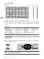
6010 电机性能
性能曲线
Τ - 扭矩,
η
- 效率,I- 电流,P- 输出功率,N- 转速
以上数据均为输入电压 44.4 V 时的理论值,仅供参考。在室温 25℃、无额外冷却装置
的情况下,电流超过 20 A 为不可工作区域,15 - 20 A 为短时(约 10 - 30 s) 工作区域,
15 A 以下为可持续工作区域。实际使用时,请根据工作环境温度和散热条件控制电机运
行时间。
特征参数
速度常数 130 rpm/V 扭矩常数 0.0760 N·m/A
反电动势常数 0.0734 V·s/rad 线电感 0.224 mH
机械时间常数 200 ms 线电阻 230 mΩ
电机转子惯量 70 kg·mm
2
热时间常数 600 s
转子总惯量 (含 桨) 700 kg·mm
2
9. 常见问题
如何预防射桨?
螺丝和桨盖上印有标识线来提示螺丝是否松动。每次起飞前都检查此
标识线,确保飞行安全。
若在安装时交换两颗桨叶螺丝的安装位置或使用其它的螺丝,
此标识线将失去参照作用。
(N·m)
1
0
2
3
4
5
6
7
8
9
10
1000 2000 3000 4000 5000 6000 7000
0
10
20
30
40
50
60
70
80
90
100
η
(%)
I
P
η
N (rpm)
I (A)
0
50
100
150
200
250
P (W)
0
20
400
600
800
1000
1200
T
T

©
2016
大疆创新 版权所有
19
CH
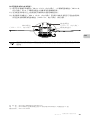
如何更换桨叶或桨盖?
1) 使用 2 颗桨叶螺丝(M4×13.3,内六角)、2 颗桨盖螺丝(M3×9,
内六角)和 4 个螺旋桨垫片重新安装螺旋桨。
2) 在桨盖和电机上的安装孔螺纹内使用螺丝胶。
3) 安装桨叶螺丝(M4×13.3,内六角)至桨叶被夹紧且可自由旋转,
然后安装两颗桨盖螺丝(M3×9,内六角)并拧紧。
确保拧紧螺丝。螺丝过松可能会导致螺丝胶无法完全干燥
固化。
桨盖螺丝
(M3×9,内六角)
桨叶螺丝
(M4×13.3,内六角)
螺旋桨垫片
制 造 商:深圳市大疆创新科技有限公司
地 址:深圳市南山区高新南四道 18 号创维半导体设计大厦西座 14 层
服务热线:400-700-0303

Copyright
©
2016 大疆创新 版权所有
内容如有更新,恕不另行通知。
您可以在 DJI 官方网站查询最新版本《用户手册》
http://www.dji.com/cn/product/e2000
如果您对说明书有任何疑问或建议,请通过以下电子邮箱联系我们:
。
中国印制
微信扫一扫关注 DJI 公众号
www.dji.com/cn/support
DJI 技术支持
-
 1
1
-
 2
2
-
 3
3
-
 4
4
-
 5
5
-
 6
6
-
 7
7
-
 8
8
-
 9
9
-
 10
10
-
 11
11
-
 12
12
-
 13
13
-
 14
14
-
 15
15
-
 16
16
-
 17
17
-
 18
18
-
 19
19
-
 20
20


