Azbil F4Q ユーザーマニュアル

タイプ
ユーザーマニュアル
J1
CP-UM-5978JECK
デジタルマスフローコントローラ
形 F4Q
取扱説明書
このたびは本製品をご購入いただき、まことにありがとうございます。こ
の取扱説明書には、製品を安全に正しくご使用いただくための必要事項
が記載されております。本製品を使用した装置の設計、保守を担当され
る方は、必ずお読みになり、理解したうえでご使用ください。いつもお
手元においてご活用ください。
ご注文・ご使用に際しては、次のURLより「ご注文・ご使用に際してのご
承諾事項」を必ずお読みください。
https://www.azbil.com/jp/product/factory/order.html
お願い
この取扱説明書は、本製品をお使いになる担当者のお手元に確実に届く
ようにお取りはからいください。
この取扱説明書の全部、または一部を無断で複写、または転載すること
を禁じます。この取扱説明書の内容を将来予告なしに変更することがあ
ります。
この取扱説明書の内容については、万全を期しておりますが、万一ご不
審な点や記入もれなどがありましたら、当社までご連絡ください。
お客さまが運用された結果につきましては、責任を負いかねる場合がご
ざいますので、ご了承ください。
安全上の注意
この安全上の注意は、製品を安全に正しくお使いいただき、あなたや他
の人々への危害や財産への損害を未然に防止するためのものです。安全
上の注意は必ず守ってください。また、内容をよく理解してから本文を
お読みください。
● シンボル表示の意味
警告 取り扱いを誤った場合に、使用者が死亡または重傷
を負う危険の状態が生じることが想定される場合。
注意 取り扱いを誤った場合に、使用者が軽傷を負うか、
または物的損害のみが発生する危険の状態が生じる
ことが想定される場合。
警告
爆発限界内にあるガスを流さないでください。
爆発事故につながるおそれがあります。
油分を含んだガスを流した場合は、酸素を流さないでください。
接ガス部に油分が付着していると発火するおそれがあります。
爆発性のある雰囲気や可燃性の液体や蒸気のあるところでは
使用しないでください。
本器は、仕様に記載された条件の範囲内で使用してください。
火災、故障のおそれがあります。
注意
仕様に記載のないガス種類の使用可否については、事前に当
社までお問い合わせください。機器故障やO リングのシール
性が損なわれるおそれがあります。
酸素を流す場合は、次の点を守ってください。
• 配管作業は、酸素の取り扱いに関する専門知識を有する方
が行ってください。
• 配管は禁油処理されたものを使用してください。
• 本器と接続する前に配管のごみやバリなどを取り除いてく
ださい。
• 接ガス部を素手で触らないでください。
外部の遮断弁を閉じている場合は、本器のバルブを閉じてくだ
故障のおそれがあります。
本器を持ち運ぶ際は、底面を持ってください。けがや本器の
故障のおそれがあります。
本器は精密機器です。落としたり、ぶつけたりして衝撃を与え
ないよう十分に注意してください。破損する場合があります。
注意
流路に異物が混入しないようにポリ袋などに入れて保管・運
搬してください。
本器に異常が生じた際に損害が想定される場合には、適切な
冗長設計を行ってください。
本器を取り付けるときは、トップパネル部を下向きにしないで
ください。トップパネル部が下向きだと故障の原因となります。
取り付けは振動のないよう確実に固定してください。誤動作
および故障の原因となります。
取り付けるときは本器の重量をささえられるよう確実に固定
してください。けがや本器の故障のおそれがあります。
本器のコネクタ部にほこり、ごみが付着した状態でコネクタ
接続や通電をしないでください。火災、機器故障のおそれが
あります。
異物が本器流路内に流入しないようにしてください。配管内
のさび・水滴・オイルミスト・ほこりなどが本器内に流入す
ると、計測・制御誤差の発生や本器の破損につながるおそれ
があります。
バーナの空燃比制御に使用する場合、逆火の発生を防ぎ、ま
た逆火が発生したときでも本器に影響を及ぼさないように計
装面での対策をしてください。バーナの逆火による配管内の
圧力上昇や火炎は、故障の原因となります。
本器の下流側近傍に絞りや圧力損失の大きな機器を接続しな
いでください。ハンチングの原因となります。
ご使用前に製品本体および配管接続部からガスの漏えいがな
いことを確認してください。また使用開始後も定期的に漏え
いのないことを確認してください。とくに危険性を伴うガ
スにて使用する場合には、お客さまご自身の責任において、
万一ガスが漏えいした場合に備え、ガス漏えいを確実に検知
する手段などの措置を講じてください。
温度変化の大きい環境に設置する場合は、結露しないように十分
に乾燥したガスで置換してください。故障のおそれがあります。
仕様に記載された流量レンジで使用してください。また、過
大流量にならないよう、適正な供給圧力の管理と絞り弁の設
置などを配慮した計装を行ってください。レンジ上限値を超
えると、表示値・出力値が実際の流量よりも著しく低い値を
示す場合があります。
耐圧以上の圧力をかけないでください。
破損するおそれがあります。
動作差圧範囲内で使用してください。ハンチングを起こし、
バルブが故障するおそれがあります。
本器をエアーブローしたり、流路内をウエスで拭かないでく
ださい。センサ部故障の原因となります。
本器を洗浄したり、流路内を蒸気洗浄しないでください。セ
ンサ部故障の原因となります。
ケーブルを接続した状態で、ケーブルやコネクタに過大な力
を加えないでください。製品が破損する原因となります。
電源が切れている状態で、瞬時流量設定入力端子に電圧を印
加しないでください。誤作動および故障の原因となります。
F4Q内の流体圧力を開放する場合は、出口側へガスを流すこ
とで圧力を開放してください。
入口側へ流体圧力を開放すると、整流部が影響を受け、計測
制御誤差の原因となるおそれがあります。
確認してください
お買い上げいただいた形 F4Qは、次のものが同梱されています。
•マスフローコントローラ本体  1
•分離表示器  1*1
•分離表示器用ケーブル  1*1
•取扱説明書(本書) CP-UM-5978JECK  1
•検査成績書  1*2
1 分離形選択時のみ
2 検査成績書選択時のみ
概 要
本器は独自開発の微小熱式流速センサを用いた高速応答高精度
高機能なマスフローコントローラです。
各部の名称と機能
トップパネル
部品名称 用途
ステータスランプ 異常状態やバルブの制御状態を通知するLED
通信ランプ 機器の通信状況を示すためのLED
表示部 制御値のモニタや各種設定、実行するための表示
デバイス
バルブ制御キー バルブ動作モードを切り替えるための専用キー
方向キー 画面遷移、カーソル移動、数値入力など、汎用的
な用途で使われるキー
取り扱い上の注意
キー操作の際には先のとがったもの(ドライバの先や針など)
押さないでください。故障の原因となります。
本 体
一体形
外部接続用
ローダ
micro USB端子
表示部
方 向キー
トップ パ ネ
配管接続口
入口側 配管接続口
出口側
分離形
外部接続用
分離表示用
ローダ
micro USB端子
配管接続口
入口側 配管接続口
出口側
分離表示器
表示部
分離表示用(背面)
取り付け
取付場所
本器は次のような場所を避けて設置してください。
•仕様の範囲を超えた高温、低温、高湿度、低湿度になる場所
•急激な温度変化があり、結露するような場所
•硫化ガスなど腐食性ガスのある場所
•可燃性のガス、液体や蒸気のある場所
•雰囲気中にじん埃、塩分、鉄粉などの導電性物質、水滴、オ
イルミスト、有機溶剤などが多く含まれる場所
•仕様の範囲を超えた機械的振動、衝撃のある場所
•直射日光、風雨が当たる場所
•油、薬品などの飛沫がかかる場所
•高圧線の下、溶接機および電気的ノイズの発生源の近く
•電磁界の影響のある場所
取り扱い上の注意
本器のバルブは完全閉止能力がありません。完全閉止が
必要な場合は別途遮断弁を設けてください。
異物が流入するおそれがある場合には、本器の上流に0.1
μm以上の異物除去能力を持つフィルタ、ストレーナ、
ミストトラップなどを設け、定期的に点検、交換などを
行ってください。
取付方法
継手の取り付け(UNF 接続のとき)
継手取り付け時(UNF 接続の場合)は傷防止のため、本体下
部をウエスなどで養生したうえでバイスで固定し、継手側
を回して取り付けてください。
本体下部を固定しないと破損する場合があります。
本体
ウエスなど
コネクタのラッチ
継手を締め付けるとき本体上部を手などで押さえないでく
ださい。変形して破損する場合があります。
本体取り付け
形 F4Q9200/9500/0002/0005/0020/ 0050(B,C)/0100
本器はオプション部品F9Y4QB1 を使用して取り付けるこ
とを推奨します。
F9Y4QB1については  詳細編 CP-SP-1461 をご覧くだ
さい。本器底面の穴位置は次の図をご覧ください。本器底
面の取付ねじ穴を使用して、裏面からM4 ねじ2 本で固定し
てください。 単位:mm
2×M4 ねじ深さ 5 min
30±0.5 30±0.5
11±0.5
15
±0.5
形 F4Q0050(J, K)/0200
本器はオプション部品F9Y4QB2 を使用して取り付けるこ
とを推奨します。
F9Y4QB2については  詳細編 CP-SP-1461 をご覧くだ
さい。本器底面の穴位置は次の図をご覧ください。本器底
面の取付ねじ穴を使用して、裏面からM4 ねじ4 本で固定し
てください。
11.5±0.5
27 ±0.5
4
×
M4
ねじ深さ5 min
110±0.5
25.3±0.5
ルブ 制 御キー
方 向キー
タスラン
通 信ラン
表示部
J2
〔ご注意〕 資料の記載内容は、予告変更する場合すの
(30)
本 社 〒100-6419 東京都千代田区丸の内 2-7-3 東京ビル
北海道支店
東北支店
北関東支店
東京支社
(011)211 1136
(022)290 1400
(048)621 5070
(03)6432 5142
中部支社
関西支社
中国支店
九州支社
(052)265 6247
(06)6881 3383~4
(082)554 0750
(093)285 3530
〈COMPO CLUB〉 https://www.compoclub.com/
〈アズビル株式会社〉 https://www.azbil.com/jp/
製品のお問い合わせは…
コーンター : 0466-20-2143
専用取付金具(別売品)での取り付け
本器底面と取付金具をねじで固定したあ
と、表面からねじ4 本で取付金具を固定し
てください。
配管の接続
•配管時は、継手の六角部を固定し、配管側を回して接続
してください。
•ガスは必ず本体に表示された の向きに従って流れ
るようにしてください。逆方向では正しい流量制御がで
きません。
•配管後はガスのリークがないことを確認してください。
•シール剤は適量につけ、
ねじの先端から2 山には
塗らないでください。ま
た、管内のごみやバリは
取り除いてください。
•Swagelok、VCR 接続タイプでは、該当する接続継手メー
カーの取扱説明書に記載されている注意事項をご確認の
うえ、配管接続を行ってください。(継手形番は、  詳細
編 CP-SP-1461をご覧ください)
分離表示器の取り付け
①パネル穴あけ図に従って、パネルに取付穴をあけてくだ
さい。
②分離表示器をパネル前面から挿入してください。
③取付器具のつめが本体の溝に確実に入るまでパネルに押
し付けてください。
④取付器具上下のねじを締めてください。
取り扱い上の注意
付属の取付器具のねじを締めて、取付器具が動かなくなっ
たガタのない状態から半回転だけねじを回してパネルに
固定してください。ねじを締めすぎるとケースが変形す
るおそれがあります。
外形寸法 単位:mm
本 体
•F4Q9200/9500/0002/0005/0020/0050(B,C)/0100
34.6
130
90
(92.9)
84
62.6
8.6
15.5
18.5
37
•F4Q0050(J,K)/0200
34.6
98
45
143.9
132 max
23.2
2×3/4-16UNF
8.6
76.6
150
50
25
•分離形表示付きモデル/表示器
33
3810.930.6
(32.9)
88
93
•パネル穴あけ図
パネルカット寸法(推奨)密着取付個別取付
※パネル厚さ 6 mm 以下
89±0.2
89±0.2
(93×N-4)
±0.2
(38×N-4)
±0.2
34±0.2
34±0.2
34±0.2
89±0.2 30 以上
30 以上
取り扱い上の注意
MQVのパネルカット寸法にも取り付けできますが、取付時
は分離表示器が穴の中心になるように取り付けてください。
外部接続用コネクタ
コネクタ仕様
•ピン配列
•信号表
PinNo.
信号名 内容 備考
1 DA RS-485通信DA 接続方法については、 通信編
CP-SP-1458 をご覧ください
2 DB RS-485通信DB
3 S.GND
RS
-
485通信(-)
4 AI アナログ入力(+) 流量設定(SP)入力
0 ~ 5V/1 ~ 5V/4 ~ 20mA入力
5 AO アナログ出力(+) 制御流量(PV)出力または設定流量
(SP)出力
0 ~ 5V/1 ~ 5V/4 ~ 20mA出力
6 A.GND アナログ信号(-) アナログ信号のコモン
7 P.GND 電源DC24V(-) 定格 DC24V± 10%
配線抵抗による電圧降下を少なくす
るため、並列に2本ずつ電源に接続
してください
8 P.GND 電源DC24V(-)
9
POWER(24V)
電源DC24V(+)
10
POWER(24V)
電源DC24V(+)
11 DO1 デジタル出力1(+) Nch オープンドレイン非絶縁出力
12 DO2 デジタル出力2(+)
13 DO3 デジタル出力3(+)
14 D.GND デジタル信号(-) デジタル信号のコモン
15 DI1 デジタル入力1(+) オープン/ GND 2 段切替入力
16 DI2 デジタル入力2(+)
17 DI3 デジタル入力3(+)
18 D.GND デジタル信号(-) デジタル信号のコモン
19 ― 未接続
20 ― 未接続
1 本器内部の電源回路と入出力回路は絶縁されています。
2 A.GND、D.GND、S.GND は本器内部で接続されていますが、必ず別々のグラ
ンド配線を行ってください。
3 19 pin、20pinには何も接続しないでください。
4 デジタル入力をリレー接点により切り替える場合は、微小電流用のリレー(金
接点タイプ)を使用してください。
微小電流用のリレーを使用しないと、接点の接触不良により誤動作を起こすお
それがあります。
廃 棄
電気電子機器廃棄に関する注意(環境保護)
本製品はWEEE 指令による産業用途製品です。
電気および電子機器を家庭ごみとして廃棄しないでください。
製品にはリサイクルに役立つ貴重な原材料が含まれているため、
古い製品は、お客様にて正しい廃棄/ リサイクルのために認定さ
れた回収場所に戻す必要があります。
良い例 悪い例
シール剤
シール剤
端子No.1
端子No.10
端子No.11
端子No.20
仕 様
項目
F4Q9200
F4Q0002
F4Q0020
F4Q9500
F4Q0005 F4Q0050(B,C) F4Q0100 F4Q0050(J,K) F4Q0200
バルブ方式 比例ソレノイドバルブ
ガス種類*1
フッ素ゴムガスケト仕
空気/窒素、酸素、アルゴン、炭酸ガス、都市ガス13A(45MJ/m3、メタン 100%、プロパン 100%、ブタン 100%
EPDMガスケット仕様
空気/窒素、アルゴン、炭酸ガス ― ―
空気/窒素、
アルゴン、炭酸ガス
制御 制御範囲 1 ~ 100%FS
応答性*2 設定±2%FS以内に0.3s(TYP.) 設定±2%FS以内に0.7s(TYP.)
精度
(基準条件にて)
*3 F4Q9200
±1%SP(40Q100%)、±0.4%FS(1Q<40%)
F4Q9500/0002/0005/0020/0050(B,C)
±1%SP(15Q100%)、±0.15%FS(1Q<15%
±1.5%SP
(60Q100%)
±0.9%FS
(1Q<60%)
±1.5%SP
(30Q100%)
±0.45%FS
(1Q<30%)
±1%SP
(30Q100%)
±0.3%FS
(1Q<30%)
圧力 標準差圧 200kPa(入口圧:200kPa(gauge)、出口圧:0kPa(gauge)
50kPa(入口圧:
50kPa(gauge)
出口圧:0kPa
(gauge)
200kPa(入口圧:
200kPa(gauge)
出口圧:0kPa
(gauge)
動作差圧範囲*4 50 ~ 300kPa 5 ~ 300kPa 100 ~ 300kPa 200 ~ 400kPa 10 ~ 100kPa 100 ~ 300kPa
許容入口圧 0.5MPa(gauge)
耐圧 1MPa(gauge)
動作条件 動作温度範囲 10 ~+60℃
周囲湿度範囲 10 ~ 90%RH(結露なきこと)
動作振動範囲 振動なきこと
保管条件 温度範囲 20 ~+70℃
外部リーク 1×10⁻⁸Pa・m3/s(He)(Oリング透過は含まない)
アナログ入力 入力タイプ DC0 ~ 5V / 1 ~ 5V / 4 ~ 20mA(切替可能)
入力インピーダンス 直流電圧入力時:1MΩ±10%、電流入力時:250Ω±10%
アナログ出力 出力タイプ DC0 ~ 5V / 1 ~ 5V / 4 ~ 20mA(切替可能)
最大出力 DC7V以下/ 28mA以下
外部負荷抵抗 電圧出力時:250kΩ以上、電流出力時:300Ω以下
デジタル出力 Nchオープンドレイン非絶縁出力、電源オフ時:接点開
外部供給電源:DC30V以下、最大負荷電流:30mA以下
デジタル入力 無電圧接点、またはオープンコレクタ
接点オフ時端子電圧:5V±0.5V、接点オン時端子電流:約0.5mA
通信方式*5 USB2.0②RS-485通信(3線式、CPLまたはModbusRTU)
電源定格 DC24V、消費電流300mA最大 DC24V、消費電流400mA最大
接続方式 Rc1/4、1/4Swagelok、1/4VCR、9/1618UNF Rc1/4、
3/8Swagelok、
1/2VCR、
9/1618UNF
Rc1/2、1/2Swagelok、1/2VCR、
3/416UNF
取付姿勢 水平取付(トップパネルが下向きにならないこと)、または垂直取付*6
質量 1.2kg 約3.1kg
保護構造 IP40*8 IP40*9
適合規格 EN613261、EN6132623*7
1 塩素、硫黄、酸などの腐食成分を含まない乾燥気体であること。また、ダストおよびオイルミストを含まない清浄気体であること。
2 標準差圧時の値です。
3 基準条件における当社設備との器差です。
基準条件
●流体:空気 ●入口圧:標準差圧±15kPa(gauge) ●出口圧:大気圧 ●周囲温度:23±2℃ ●ガス温度:周囲温度と同じ ●動作モード:制御中 
●振動/ 脈動:いずれも無きこと ●ウォームアップ時間:周囲温度に 2 時間以上放置、かつ電源ON後 30分以上放置 ●設置姿勢:水平 / 表示上向き 
●直管長:条件なし(形F4Q0100/形0200 以外)、25mm以上(形F4Q0100)、50mm以上(形F4Q0200)
4 動作差圧下限以下でも動作可能ですが、制御可能な流量レンジが狭くなります。
5 USB2.0は当社 PCローダソフトとの接続時に利用します。microUSBType-B(2mmax)接続に対応しています。
6 垂直取付の場合、測定値に誤差が生じます。機器の設定をすることで、設置姿勢による出力影響が補正できます。
デジタルマスフローコントローラ 形F4Q 取扱説明書 詳細編 CP-SP-1461、
デジタルマスフローコントローラ 形F4Q 取扱説明書 RS-485 通信機能編 CP-SP-1458 をご覧ください。
7 EMC試験中に、± 10%に相当する指示値や出力値の変動が生じる場合があります。
8 本体はコネクタ接続時のみ、分離表示器は表示部前面方向のみ。
9 本体はコネクタ接続時のみ、バルブ電線導入部を除く
分離表示器は表示部前面方向のみ。
©2021-2023AzbilCorporation.AllRightsReserved.
20216月 初版発行(V)
20237月 改訂5版
E1E1E1
CP-UM-5978JECK
Digital Mass Flow Controller
Model F4Q
User’s Manual
Thank you for purchasing this product. This manual contains information
for ensuring the safe and correct use of the product. Those designing
or maintaining equipment that uses this product should first read and
understand this manual. Be sure to keep it nearby for handy reference.
Please read the “Terms and Conditions” from the following URL before
ordering or use:
https://www.azbil.com/products/factory/order.html
NOTICE
Please make sure that this manual is available to the user of the product.
Unauthorized duplication of this user’s manual in part or in whole is
forbidden. The information and specifications in this manual are subject to
change without notice. Considerable effort has been made to ensure that this
manual is complete and accurate, but if you should find an omission or error,
please contact us. In no event is Azbil Corporation liable to anyone for any
indirect, special, or consequential damages as a result of using this product.
SAFETY PRECAUTIONS
The safety precautions explained below aim to ensure safe and correct use
of this product in order to prevent injury to you and others, and to prevent
property damage. Be sure to observe these safety precautions. Also, make
sure you understand the safety guidelines before reading the rest of this
manual.
Key to symbols
WARNING
Warnings are indicated when mishandling this product
may result in death or serious injury.
CAUTION
Cautions are indicated when mishandling this product
may result in minor injury or property damage only.
WARNING
Never allow gases that are within explosive limits to pass through
this device. Doing so might result in an explosion.
Do not use the oxygen model for gas that contains oil. If this
should happen, never use the flow controller again for oxygen.
The oil on the gas-contacting parts may catch fire.
Do not use this device in explosive atmospheres or near flam-
mable fluids or steam.
Use this device within the operating ranges given in the specifica-
tions. Otherwise there is a danger of fire or device failure.
CAUTION
If you wish to use this device for a gas that is not stated in the
specifications, be sure to consult with us in advance. If this device
is used for a gas that is now allowed, device failure or deteriora-
tion of the O-ring seal may result.
Observe the following when using this device for oxygen gas:
Piping should be done by a specialist experienced in handling
oxygen.
Use degreased pipes and parts.
Be sure to remove foreign matter, burrs, etc., from the pipes
before connecting this device.
Do not touch the gas-contacting parts with bare hands.
If an external shutoff valve is closed, close this device’s valve also.
Otherwise device failure may result.
When carrying this device, hold the bottom. Otherwise injury or
device failure may result.
This device is a precision instrument. Do not drop it or subject it
to impact, or it might be damaged.
CAUTION
When carrying and storing the device, put it in a plastic bag, etc.,
to prevent foreign matter from entering the flow path.
If damage could result from the abnormal functioning of this de-
vice, include appropriate redundancy in the system design.
When mounting this device on a pipe, make sure that the top
panel does not faces downward. If the top panel faces downward,
device failure may result.
When installing, attach securely to prevent vibration. Vibration
may cause malfunction or device failure.
Install this device securely so that it does not come off. Otherwise
injury or device failure may result.
Do not connect a connector or supply power to this device if the
connector of this device is dusty or dirty. There is a danger of fire
or device failure.
Prevent foreign matter from entering the flow path of this device.
If rust, water droplets, oil mist, or dust from the pipes enters the
device, a measurement or control error may occur, or the device
may be damaged.
When using this device for air-fuel ratio control of a burner, pre-
vent the occurrence of flashback and also take countermeasures
for the instrumentation to protect the device even if flashback oc-
curs. Pressure increase or fire in the pipes caused by the backfire
of the burner could damage the device.
Do not connect equipment that causes a large throttling or pres-
sure loss near the piping that is downstream of this device. Doing
so may cause hunting.
Check the product connections and pipe connections for leak-
age before use. Also, check the connections for leakage regularly
after the start of use. It is the users responsibility to ensure that
gas leaks can be reliably detected. This is especially important if a
dangerous gas is used.
If the device is installed in an environment with significant tem-
perature change, flow a sufficiently dry gas through the pipes to
remove any remaining wet gas in order to prevent water conden-
sation. There is a danger of device failure.
Use this device within the flow rate range given in the specifica-
tions. To prevent excessive flow, use a suitable means to control
the supply pressure or use a throttle valve or the like to control
the flow rate. If the flow rate exceeds the upper limit, both the
flow rate display and the output voltage/current may indicate
considerably lower values than the actual flow rate.
Do not subject the product to pressure beyond the rated pressure
resistance range. The product may be damaged.
Use this device within the operating differential pressure range.
Otherwise hunting may occur and the valve may be damaged.
Do not blow air through the device or wipe the inside of the flow
path with a rag. Doing so may cause sensor malfunction.
Do not wash the device or steam-clean the inside of the flow
path. Doing so may cause sensor malfunction.
Do not apply excessive force on the cable or connector while the
cable is connected. Excessive force may damage the product.
Do not apply voltage to the instantaneous flow rate setting input ter-
minal while the power is off. Malfunction or device failure may result.
To release the fluid pressure inside the F4Q, vent the gas from the
outlet port.
Releasing the fluid pressure from the inlet port may affect the
rectifying section and cause errors in measurement and control.
UNPACKING
The following items should be included in your purchase.
Mass flow controller: 1
Separate display unit: 1*1
Cable for separate display unit: 1*1
User’s Manual No. CP-UM-5978JECK (this document): 1
Inspection report: 1*2
*1. Only when the separable model was purchased.
*2. Only when the inspection report option was selected.
OVERVIEW
This mass flow controller incorporates the thermal micro-flow sensor devel-
oped by Azbil Corporation, and features high-speed response, high accuracy,
and high functionality.
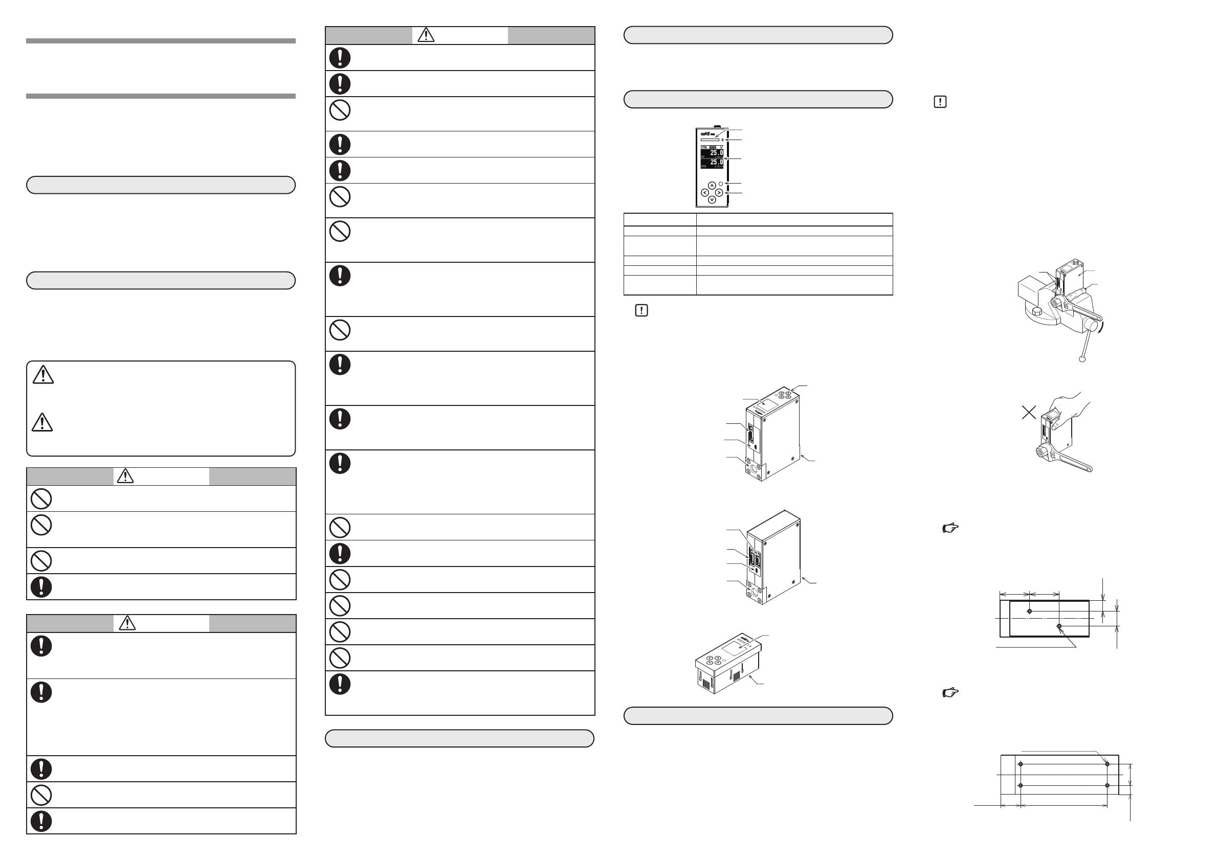
NAMES AND FUNCTIONS OF PARTS
Top panel
Part name Application
Status indicator An LED to indicate abnormalities or valve control status
Communication
indicator
An LED to indicate the communication status of the
device
Display Used to monitor controlled values or to specify settings.
Valve control key Used to switch valve operation modes.
Arrow keys Used for general purposes such as screen transitions,
cursor movement, and numerical value input.
Handling Precautions
Do not press the keys with a screwdriver, needle, or other sharp-
tipped object. Device failure may result.
Main unit
z Integrated model
Connector for external connection
Micro USB terminal for loader
Display
Arrow keys
Top panel
Inlet pipe connection port Outlet pipe connection port
z Separable model
Connector for external connection
Connector for separate display unit
Micro USB terminal for loader
Inlet pipe connection port Outlet pipe connection port
Separate display unit
Display
Connector (on the back)
INSTALLATION
Installation location
Do not install this product in a place with any of the following
characteristics:
Temperature or humidity outside the specified high and low limits
Sudden temperature changes resulting in condensation
Corrosive gases such as sulfide gas
Flammable gas, liquid or vapor
Large amounts of dust, salt, iron powder or other conductive sub-
stances, water droplets, oil mist, or organic solvents
Mechanical vibration or shock outside the range of the specifications
Direct sunlight, wind, or rain
Splashing of fluids such as oil or chemicals
Proximity to high-voltage lines, welding machines, or other sources of
electrical noise
Strong electromagnetic fields
Handling Precautions
The valve on this device cannot completely stop the flow of gas. If
complete shutoff is required, provide a separate shutoff valve.
If there is a possibility of foreign matter entering the device,
install an upstream filter, strainer, or mist trap capable of elimi-
nating foreign matter 0.1 µm or greater in diameter. Be sure to
inspect and replace the filter at regular intervals.
Installation method
z Installing fittings for UNF connections
When attaching the fitting (on a UNF connection), hold the lower part
of the main unit in a vise gripped between rags to protect the finished
surfaces, and turn the fitting to tighten.
The device may be damaged if the lower part of it is not secured.
Main unit
Rag
Connector latches
Do not hold the upper part of the main unit when tightening the fitting.
Doing so may cause deformation and damage.
Installing the main unit
z Model F4Q9200/9500/0002/0005/0020/0050 (B,C)/0100
Installing the device using the F9Y4QB1 (an optional part) is
recommended.
Users manual (CP-SP-1461E) for model F4Q (for information on
the F9Y4QB1)
The figure below shows the positions of the mounting holes on the base of
the device. Install the device with two M4 screws using the holes.
Unit: mm
M4 screw (2), depth 5 min.
30±0.5 30±0.5
11±0.5
15
±0.5
z Model F4Q0050 (J,K)/0200
Installing the device using the F9Y4QB2 (an optional part) is
recommended.
Users manual (CP-SP-1461E) for model F4Q (for information on
the F9Y4QB2)
The figure below shows the positions of the mounting holes on the base of
the device. Install the device with four M4 screws using the holes.
Unit: mm
11.5±0.5
27 ±0.5
M4 screw (4), depth 5 min.
110±0.5
25.3±0.5
Valve control key
Arrow keys
Status indicator
Communication indicator
Display
E2E2
1-12-2 Kawana, Fujisawa
Kanagawa 251-8522 Japan
URL
: https://www.azbil.com
(11)
Specifications are subject to change without notice.
©2021-2023 Azbil Corporation. All Rights Reserved.
1st edition: June 2021 (T)
5th edition: July 2023 (S)
z Installation using a dedicated mounting bracket (sold
separately)
After attaching the mounting bracket to the bottom of
the device with screws, secure the mounting bracket in
place with four screws.
z Piping connection
When connecting the device to the pipes, hold the hexagonal
part of the fitting in place and turn the pipe.
Make sure that the gas flows into the device in the direction indi-
cated by on the main unit. If the gas direction is reversed,
the flow rate cannot be controlled correctly.
After connecting the piping, check for gas leaks.
Apply an appropriate amount of sealant. Do not put sealant on
the two threads closest to the tip.
In addition, remove any dust or
burrs from the inside of the pipes.
Before connecting pipes with
Swagelok or VCR fittings, check
the instructions in the manual pro-
vided by the manufacturer of the fitting. User’s manual (No.
CP-SP-1461E) for model F4Q (for model numbers of fittings)
Installing the separate display unit
(1) Make mounting holes in the panel according to the panel cut-
out dimensions.
(2) Insert the display unit from the front of the panel.
(3) From behind the panel, push the mounting bracket supplied
with the display unit onto the panel until the catches of the
bracket are fully engaged with the grooves in the display unit.
(4) Tighten the screws at the top and bottom of the bracket.
Handling Precautions
When installing the display unit on the panel, tighten the sup-
plied mounting bracket screws until there is no play between
the bracket and the panel, and then make additional half a
turn. Excessive tightening of the screws may deform the case.
Dimensions Unit: mm
z Main unit
F4Q9200/9500/0002/0005/0020/0050 (B,C)/0100
34.6
130
90
(92.9)
84
62.6
8.6
15.5
18.5
37
F4Q0050 (J,K)/0200
34.6
98
143.9
132 max
23.2
2×3/4-16UNF
8.6
76.6
150
50
25
45
Display unit of models with separate display
33
3810.930.6
(32.9)
88
93
Panel cutout dimensions for display unit
Recommended panel cutout dimensionsGang mountingIndependent mounting
* Panel thickness: 6 mm max.
89±0.2
89±0.2
(93×N–4)±0.2
(38×N–4)±0.2
34±0.2
34±0.2
34±0.2
89±0.2 30 min.
30 min.
Handling Precautions
If the display unit is installed on a panel cutout for the MQV,
make sure that the unit is positioned in the center of the cutout.
Connector for external connection
z Connector specifications
Pin layout
Terminal No. 1
Terminal No. 10
Terminal No. 11
Terminal No. 20
Table of signals
Pin
No. Signal name Description Notes
1DA RS-485 comm., DA User’s manual for Communication
Functions (No. CP-SP-1458E) (for the
connection method)
2 DB RS-485 comm., DB
3 S.GND RS-485 comm (−)
4 AI Analog input (+) Flow rate set point (SP) input
0–5 V, 1–5 V, or 4–20 mA input
5AO Analog output (+) Controlled flow rate (PV) or flow rate set
point (SP) output
0–5 V, 1–5 V, or 4–20 mA output
6 A.GND Analog signal (−) Common ground for analog signals
7 P.GND 24 V DC (−) power Rated 24 V DC ±10 %
Connect two wires each in parallel to the
power supply to reduce the voltage drop
caused by wiring resistance.
8 P.GND 24 V DC (−) power
9
POWER (24 V)
24 V DC (+) power
10
POWER (24 V)
24 V DC (+) power
11 DO1
Digital output 1 (+)
Nch open drain non-isolated output
12 DO2
Digital output 2 (+)
13 DO3
Digital output 3 (+)
14 D.GND Digital signal (−) Common ground for digital signals
15 DI1 Digital input 1 (+) 2-way (OPEN/GND) switching input
16 DI2 Digital input 2 (+)
17 DI3 Digital input 3 (+)
18 D.GND Digital signal (−) Common ground for digital signals
19 Not connected
20 Not connected
Note 1. The power supply circuit and I/O circuit inside the device are isolated.
Note 2. Even though the A.GND, D.GND, and S.GND are connected internally, be
sure to ground them separately.
Note 3. Do not input any signal to pins 19 and 20.
Note 4. When switching the digital input by relay contacts, use an appropriate
relay intended for microcurrent use (with gold contacts).
Failure to use a relay designed for microcurrents may result in malfunc-
tion due to poor contact.
Correct Incorrect
SealantSealant
SPECIFICATIONS
Item
F4Q9200
F4Q0002
F4Q0020
F4Q9500
F4Q0005 F4Q0050 (B,C) F4Q0100 F4Q0050 (J,K) F4Q0200
Valve type Proportional solenoid valve
Gas type*1Fluoroelastomer gasket Air/nitrogen, oxygen, argon, carbon dioxide, fuel gas 13A (45 MJ/m3), 100 % methane, 100 % propane, 100 % butane
EPDM gasket Air/nitrogen, argon, carbon dioxide
Air/nitrogen, argon,
carbon dioxide
Control Control range 1 to 100 % FS
Response time*20.3 s (typ.) to the setting ±2 % FS 0.7 s (typ.) to the setting ±2 % FS
Accuracy (under standard
conditions)*3
F4Q9200
±1%SP (40 ≤ Q ≤ 100%), ±0.4%FS (1 ≤ Q < 40%)
F4Q9500/0002/0005/0020/0050 (B,C)
±1%SP (15 ≤ Q ≤ 100%), ±0.15%FS (1 ≤ Q < 15%)
±1.5% SP
(60 ≤ Q ≤ 100%)
±0.9% FS
(1 ≤ Q < 60%)
±1.5% SP
(30% ≤ Q ≤ 100%)
±0.45% FS
(1% ≤ Q < 30%)
±1% SP
(30% ≤ Q ≤ 100%)
±0.3% FS
(1% ≤ Q < 30%)
Pressure Standard differential
pressure
200 kPa (inlet pressure: 200 kPa (gauge); outlet pressure: 0 kPa (gauge)) 50 kPa (inlet pressure:
50 kPa (gauge); outlet
pressure: 0 kPa (gauge))
200 kPa (inlet pressure:
200 kPa (gauge); outlet
pressure: 0 kPa (gauge))
Operating differential
pressure*4
50 to 300 kPa 5 to 300 kPa 100 to 300 kPa 200 to 400 kPa 10 to 100 kPa 100 to 300 kPa
Allowable inlet pressure 0.5 MPa (gauge)
Pressure resistance 1 MPa (gauge)
Operating
conditions
Temperature −10 to +60 °C
Ambient humidity 10 to 90 % RH (without condensation)
Vibration No vibration
Storage condition
Temperature −20 to +70 °C
External leakage 1×10⁻⁸ Pa•m3/s (He) (not including O-ring permeability)
Analog input Input type 0–5 V DC, 1–5 V DC, or 4–20 mA (switchable)
Input impedance 1 MΩ ±10 % for DC voltage input, 250 Ω ±10 % for current input
Analog output Output type 0–5 V DC, 1–5 V DC, or 4–20 mA (switchable)
Maximum output 7 V DC / 28 mA
External load resistance 250 kΩ min. for voltage output, 300 Ω max. for current output
Digital output Nch open drain non-isolated output, when power off: open contacts
External power supply: 30 V DC max., maximum load current: 30 mA max.
Digital input Non-voltage contacts or open collector
Terminal voltage with contacts OFF: 5 ±0.5 V, terminal current with contacts ON: approx. 0.5 mA
Communication method*5(1) USB 2.0 (2) RS-485 (3-wire system, CPL or Modbus RTU)
Power rating 24 V DC, current consumption: 300 mA max. 24 V DC, current consumption: 400 mA max.
Connection method Rc 1/4, 1/4 Swagelok, 1/4 VCR, 9/16–18 UNF Rc 1/4, 3/8 Swagelok,
1/2 VCR, 9/16–18 UNF
Rc 1/2, 1/2 Swagelok, 1/2 VCR, 3/4–16 UNF
Mounting orientation Horizontally (the top panel should not face downward) or vertically*6
Weight Approx. 1.2 kg Approx. 3.1 kg
Protective structure IP40*8IP40*9
Standards compliance EN 61326-1, EN 61326-2-3 *7
*1. The gas must be dry and not contain corrosive components (chlorine, sulfur, acid, etc.). Also, it must be clean, without dust or oil mist.
*2. Value at standard differential pressure.
*3. Instrument error under standard conditions according to our equipment.
Standard conditions
Fluid: air
Inlet pressure: standard differential pressure ±15 kPa (gauge)
Outlet pressure: atmospheric pressure
Ambient temperature: 23 ±2 °C
Gas temperature: same as ambient temperature
Operation mode: control mode
Vibration/pulsation: none
Warm-up time: leave at ambient temperature
for 2hours or more, and leave for 30 minutes or more after turning on the power
Installation orientation: horizontal with the display facing upward
Straight
pipe length: any (other than model F4Q0100/model 0200), 25 mm or longer (model F4Q0100), 50 mm or Longer (model F4Q0200)
*4. Operation is possible below the minimum operating differential pressure, but the controllable flow rate range narrows.
*5. USB 2.0 is used when connecting to Azbils PC loader software. This device supports micro USB Type-B (2 m max.) connection.
*6. In the case of vertical mounting, an error occurs in measurements. The error can be corrected with device settings.
For details, refer to the following documents:
Digital Mass Flow Controller Model F4Q User’s Manual (CP-SP-1461E)
Digital Mass Flow Controller Model F4Q User’s Manual for RS-485 Communication Functions (CP-SP-1458E)
DISPOSAL
Disposal of Electrical and Electronic Equipment (for Environmental Protection)
This is an industrial product subject to the WEEE Directive.
Do not dispose of electrical and electronic equipment in the same way as household waste.
Old products contain valuable raw materials and must be returned to an authorized collection point for correct disposal or recycling.
*7. During EMC testing, the reading or output may fluctuate by the equivalent
of ±10 % FS.
*8. Main unit: only when the connector is connected.
Separate display unit: only the front of the display
*9. Main unit: only when the connector is connected. The location where the
valve cable enters the unit is not included.
Separate display unit: only the front of the display
C1
CP-UM-5978JECK
数字质量流量控制器
型号F4Q
使用说明书
非常感谢您购买本产品。本使用说明书记载了正确安全地使用产品的必要事
项。对于承担使用本产品装置的设计、维护的工作人员,请务必仔细阅读,
并在理解的基础上使用本机。请常备此手册以供参考。
在订货和使用时,请务必登入以下网站,仔细阅读“关于订购与使用的承
诺事项“。
https://www.azbil.com/cn/products/factory/order.html
要 求
请务必把本使用说明书送到本产品使用者手中。
禁止擅自复印和转载全部或部分本使用说明书的内容。今后内容变更时恕
不事先通知。
本使用说明书的内容,经过仔细审查校对,万一有错误或遗漏,请向本公
司提出。
对客户应用结果,本公司有不能承担责任的场合,敬请谅解。
安全注意事项
本安全注意事项是为了正确安全使用本产品,防患于未然,以免给您及他
人造成人身损害及财产损失。请务必遵守本安全注意事项。另外,请在阅
读本书时充分理解所述内容
符号表示的含义
警告 错误使用时,可能会造成使用者死亡或负重伤的危险
状态。
注意 错误使用时,可能会发生使用者负轻伤或造成物品损
坏的危险状态。
警告
请不要让处于爆炸极限内的气体流过。
否则会引起爆炸事故。
流过了含油分气体的场合,请不要让氧气流过。
接气部附着有油分时,有可能会起火。
请勿在有爆炸性环境或可燃性液体或蒸汽的场所使用。
请在规格书中记载的使用条件范围内使用本产品。否则,可能
会引起火灾或产品故障。
注意
有关是否可以使用非标准气体,请事先咨询本公司。否则可能
会造成设备故障和损伤O型圈的密封性。
使用氧气的场合,请遵守以下事项。
请由具有使用氧气相关专业知识的人员进行配管作业。
请使用经过禁油处理的配管。
在与本机连接前,请去除配管的垃圾和毛刺等。
请勿直接用手触摸接气部。
关闭外部的切断阀的场合,请关闭本机的阀门。否则,可能会
引起产品故障。
搬运本机时,请握住本机底部。否则,可能会受伤或造成本机
故障
本机是精密仪器。请充分注意不要跌落、碰撞本机,以免对本
机造成冲击。否则,本机有可能会破损。
保管/搬运时,请把本机装入塑料袋等中以免异物混入流路中。
当本机发生异常而有可能引起损害的场合,请进行恰当的冗余
设计。
安装本机时,请勿将顶部面板部朝下。顶部面板部朝下时会产
生故障。
安装时请切实固定,以免本机产生振动。否则会引起误动作和
产生故障。
注意
安装时请切实固定以支撑本产品的重量。否则,可能会受伤或
导致本机故障。
请勿在本机的连接器部附着灰尘、垃圾的状态下连接连接器或
通电。否则,可能会引起火灾或产品故障。
请避免让异物进入本机的流路内。配管内的锈迹、水滴、油雾、
灰尘等进入本机内时,会引起检测 、控制误差和损伤本机。
用于燃烧器空燃比控制的场合,请采取防止产生逆火和即使产
生逆火也不会影响本机的设计对策。因燃烧器的逆火而导致配
管内压力上升或产生火焰会引起故障。
请勿在本机下游侧附近进行节流或连接压力损失大的设备。否
则会引起振荡。
在使用前请确认从产品主体及配管连接部没有气体泄漏。另外,
开始使用后也请定期确认无泄漏。特别是使用具有危险性的燃
气时,客户自身有责任采取措施,防止万一燃气泄漏时能可靠
地检测燃气泄漏。
置在温度变化大的环境时,请用充分干燥的气体置换以免结
露。否则,可能会引起故障。
请在规格中记载的流量量程内使用。此外,为了避免流量过大,
请进行适当的供给压力管理和节流阀的设置等设计。超过量程上
限值时,显示值/输出值有可能明显比实际值低。
请勿施加超过耐压的压力。
否则会损坏本机。
请在工作差压范围内使用。否则会引起振荡,导致阀门故障。
请勿用空气吹入本机或在流路内用布擦拭。否则会导致传感器
故障。
请勿清洗本机或在流路内用蒸汽清洗。否则会导致传感器故障。
在电缆连接的状态下,请勿对电缆或连接器施加过大的力。否
则会损坏产品。
在电源切断的状态下,请勿对瞬时流量设定输入端子施加电压。
否则会引起误动作和产生故障。
如果要释放F4Q中的流体压力,请通过向出口侧流动气体来释放
压力。
当流体压力释放到入口侧时,整流部受到影响,可能导致测量和
控制误差。
请确认
您购买的型号F4Q 与下述物品同包装。
流量计主体 1
分离型流量计显示器 1 1
分离型流量计显示器用电缆 1 1
使用说明书(本书) CP-UM-5978JECK 1
检验报告 12
1 仅限选择分离型时
2 仅限选择检验报告时
概 要
本机采用了独立开发的微小热式流速传感器,是具有高速响应、高
精度、高性能的质量流量控制器。
各部分的名称和功能
顶部面板
部件名称 用途
状态灯 通知异常状态和阀控制状态的LED
通信灯 用于显示设备通信状态的LED
显示部 用于监视控制值和各种设定及执行的显示设备
阀控制键 用于切换阀运行模式的专用键
方向键 用于画面跳转、光标移动、数值输入等通用用途的
使用上的注意事项
在操作按键时,请勿用尖锐的物体(如螺丝刀头或针头)按压按
键。否则,可能会导致故障。
主 体
一体型
外部连接用连接器
编程器用
micro USB端子
显示部
方向键
顶部面板
配管连接口
入口侧 配管连接口
出口侧
分离型
分离型流量计显示器
显示部
分离显示用连接器(背面)
安 装
安装场所
请勿把本机安装在下述场所。
超过规格范围的高温、低温、高湿度、低湿度场所
温度激剧变化、结露的场所
有硫化气体等腐蚀性气体的场所
有可燃性气体、液体和蒸汽的场所
环境中有大量灰尘、盐分、铁粉等导电性物质、水滴、油雾、
有机溶剂等的场所
机械振动、冲击超过规格规定的场所
受直射阳光、风吹雨淋的场所
油、药品等飞溅的场所
高压线下、焊接机及有电气干扰发生源的附近
受电磁场影响的场所
使用上的注意事项
本机的阀不具有完全截止的能力。需要完全截止的场合,
请另行在外部设置截止阀。
有可能流入异物的场合,请在本机的上游设置能除去0.1 μm
以上异物的过滤网、过滤器、油雾器等并定期进行检查、更
换等。
安装方法
管接头的安装(UNF 连接时)
安装管接头时(UNF连接时),为了防止划伤,在主体下部
用布等进行保护后用老虎钳固定,转动管接头侧进行安装。
如果不固定主体下部,会引起破损。
主体
布等
连接器的卡扣
紧固管接头时,请勿用手按压主体上部。否则会变形而引起
破损。
主体安装
型号F4Q9200/9500/0002/0005/0020/0050(B,C)/0100
建议使用可选部件F9Y4QB1安装本机。
有关F9Y4QB1的更多信息, 请参阅详细篇CP-SP-1461T
本机底部的孔位置见下图。请使用本机底部的安装螺丝孔,从
背面用2M4螺丝固定。
单位:mm
2×M4 螺纹深度最小值为 5
30±0.5 30±0.5
11±0.5
15
±0.5
型号F4Q0050(J,K)/0200
建议使用可选部件F9Y4QB2安装本机。
有关F9Y4QB2的更多信息, 请参阅详细篇CP-SP-1461T
本机底部的孔位置见下图。请使用本机底部的安装螺丝孔,从
背面用4M4螺丝固定。
单位:mm
11.5±0.5
27±0.5
4×M4 螺纹深度最小值为5
110±0.5
25.3±0.5
使用专用安装支架(另售品)安装
用螺丝固定本机底部和安装支架后,用4颗螺
丝从表面固定安装支架。
阀控制键
方向键
状态灯
通信灯
显示部
外部连接用连接器
分离显示用连接器
编程器用
micro USB端子
配管连接口
入口侧 配管连接口
出口侧
C2
配管的连接
配管时,请固定管接头的六角部,转动配管侧进行连接。
气体的流向必须按主体上标示的 方向。逆方向时无
法正确控制流量。
配管后请确认无气体泄漏。
请涂抹适当的密封剂,从
螺纹前端起的第2牙螺纹
请勿涂抹。此外,请去除
管内的垃圾和毛刺。
SwagelokVCR 连接
型,请确认对应连接管接头厂家使用说明书中记述的注意
事项后,再进行配管连接。(管接头型号请参阅 详细篇
CP-SP-1461E
分离型流量计显示器的安装
请按照盘开孔图,在盘上开安装孔。
从盘前面放入分离型流量计显示器。
请将安装支架按压在盘上,直到安装支架的卡销牢固地插
入主体的凹槽中。
请拧紧安装支架顶部和底部的螺丝。
使用上的注意事项
请拧紧附属安装支架的螺丝,在安装支架不晃动的状态下
再转动半圈螺丝,固定在盘上。过度拧紧螺丝可能会使外
壳变形。
外形尺寸
位:mm
主 体
F4Q9200/9500/0002/0005/0020/0050(B,C)/0100
34.6
130
90
92.9
84
62.6
8.6
15.5
18.5
37
F4Q0050(J,K)/0200
34.6
98
45
143.9
132 max
23.2
2×3/4-16UNF
8.6
76.6
150
50
25
带分离显示器型/显示器
33
3810.930.6
32.9
88
93
盘开孔图
盘开孔尺寸(推荐)密集安装单独安装
※盘厚度 6 mm 以下
89±0.2
89±0.2
93×N4
±0.2
38×N4
±0.2
34±0.2
34±0.2
34±0.2
89±0.2 30 以上
30 以上
使用上的注意事项
MQV的盘开孔尺寸也能安装,但安装时请将分离显示器安
装在孔的中心。
外部连接用连接器
连接器规格
针排列
信号表
Pin No
信号名 内容 备注
1 DA RS-485 通信 DA 有关连接方法,请参阅 通信篇
CP-SP-1458E 
2 DB RS-485 通信 DB
3 S.GND
RS
-
485 通信(
4 AI 模拟输入(+) 流量设定(SP)输入
05V/1 5V/4 20 mA 输入
5 AO 模拟输出(+) 控制流量(PV)输出或者设定流量
SP)输出
05 V/1 5 V/4 20 mA 输出
6 A.GND 模拟信号(
) 模拟信号的公共端
7 P.GND 电源 DC24 V
) 额定值DC24 V ±10%
为了减少接线电阻造成的电压下降,
请分别用2根电线并列连接至电源。
8 P.GND 电源 DC24 V
9
POWER24 V
电源 DC24 V+
10
POWER24 V
电源 DC24 V+
11 DO1 数字输出1+Nch 漏级开路非绝缘输出
12 DO2 数字输出2+
13 DO3 数字输出3+
14 D.GND 数字信号(
) 数字信号的公共端
15 DI1 数字输入1+ 开路/ GND 2段切换输入
16 DI2 数字输入2+
17 DI3 数字输入3+
18 D.GND 数字信号(
) 数字信号的公共端
19 ― 未连接
20 ― 未连接
1 本机内部的电源回路与输入输出回路绝缘。
2  虽然A.GNDD.GNDS.GND在内部已连接,但务必进行单独的接地。
3  不要将任何信号连接到第 19 针和第 20 针。
4  当通过继电器接点切换数字输入时,请使用微小电流用继电器(金接点型)。
如果不使用微小电流用继电器,可能会因接触不良而引起误动作。
废 弃
关于电气电子设备废弃时的注意事项(环境保护):
本产品是基于WEEE 指令的工业用产品。
请勿将电气和电子设备作为生活垃圾废弃。
由于产品含有可回收的有价值的原材料,旧产品需要由
客户送到经批准的收集点以便正确处理/回收。
.。。
正确例 错误例
密封剂
密封剂
端子 NO.20
端子 NO.1
端子 NO.10
端子 NO.11
规 格
项目
F4Q9200
F4Q0002
F4Q0020
F4Q9500
F4Q0005 F4Q0050(B,C) F4Q0100 F4Q0050(J,K)
F4Q0200
阀形式 比例电磁阀
气体种类 1氟橡胶密封垫规格
空气/氮气、 氧气、 氩气、 二氧化碳、 城市燃气13A45MJ/m3)、 甲烷100 %、 丙烷100 %、 丁烷100
EPDM 密封垫规格 空气/氮气、氩气、二氧化碳 - - 空气/氮气、氩气
、二氧化碳
控制 控制范围 1100 FS
响应性 2设定 ±2 FS 以内时为 0.3 sTYP.) 设定 ±2 FS 以内时为 0.7 sTYP.
精度
(基准条件下) 3F4Q9200
±1%SP(40 Q100%),±0.4%FS(1 Q<40%)
F4Q9500/0002/0005/0020/0050(B,C)
±1%SP(15 Q100%),±0.15%FS(1 Q<15%)
±1.5%SP
(60 Q100%)
±0.9%FS
(1 Q<60%)
±1.5%SP
(30% Q100%)
±0.45%FS
(1% Q<30%)
±1%SP
(30% Q100%)
±0.3%FS
1% Q<30%)
压力 标准差压 200 kPa(入口压:200 kPagauge)、出口压:0 kPagauge)) 50kPa(入口
:50kPa(gauge)
、出口
:0kPa(gauge))
200kPa(入口
:200kPa(gauge)
、出口
:0kPa(gauge))
工作差压范围 450 300 kPa 5 300 kPa 100 300 kPa 200 400 kPa 10 100 kPa 100 300 kPa
容许入口压 0.5 MPagauge
耐压 1 MPagauge
工作条件 工作温度范围 10 ~+60
环境湿度范围 10 90 RH(无结露)
工作振动范围 无振动
保存条件 温度范围 20 ~+70
外部泄漏 1×10⁸ Pam3/sHe)(不含从O型圈透过)
模拟输入 输入类型 DC05 V15 V420 mA(可切换)
输入阻抗 直流电压输入时:1 MΩ±10 %、电流输入时:250Ω±10 %
模拟输出 输出类型 DC05 V15 V420 mA(可切换)
最大输出 DC7 V以下/28 mA以下
外部负载电阻 电压输出时:250 kΩ以上、电流输出时:300 Ω以下
数字输出 Nch漏级开路非绝缘输出、电源OFF时:接点开
外部供给电源:DC30 V以下、最大负载电流:30 mA以下
数字输入 无电压接点或开路集电极
接点OFF时端子电压:5 V±0.5 V、接点ON时端子电流:约0.5 mA
通信方式 5USB 2.0 RS-485通信(3线式、CPL 或者 ModbusRTU
电源额定值 DC 24 V、消耗电流300 mA 最大 DC 24 V、消耗电流400 mA 最大
连接方式 Rc1/41/4Swagelok1/4VCR9/16-18UNF Rc1/4
3/8Swagelok
1/2VCR9/16-
18UNF
Rc1/21/2Swagelok1/2VCR3/4-
16UNF
安装方位 水平安装(顶部面板不能朝下)或垂直安装 6
重量 1.2 kg 1.3 kg
保护构造 IP40 8IP40 9
适合规格 EN61326-1EN61326-2-3 7
1  不含氯气、硫黄、酸等腐蚀成分的干燥气体。并且是不含灰尘及油雾的洁净气体。
2  标准差压时的值。
3  基准条件下与本公司设备的仪器差异。
基准条件
流体:空气 入口压:标准差压± 15 kPa (gauge) 出口压:大气压 
环境温度:23 ± 2 ℃ 气体温度:与环境温度相同 运行模式:控制中 
振动/脉动:均无 预热时间:在环境温度下放置2小时以上、且电源ON后放置30分钟以上
设置方位:水平/显示朝上 
直管长度:无条件(型号F4Q0100/型号0200除外),
25 mm 以上(型号F4Q0100),50 mm以上(型号F4Q0200
4 低于工作差压下限也可运行,但可控制的流量量程变小。
5 
与本公司PC编程器软件连接时使用USB 2.0。支持micro USB Type-B (2 m max)连接。
6  垂直安装的场合,测量值会产生误差。通过对设备进行设定,
可以修正设置方位对输出的影响。详见
数字质量流量控制器 型号F4Q 使用说明书 详细篇 CP-SP-1461E
数字质量流量控制器 型号F4Q 使用说明书 RS-485 通信功能篇 CP-SP-1458E
7 在EMC测试过程中,指示值或输出值可能会出现±10%的波动。
8 仅在连接连接器时,分离型流量计显示器仅适用在显示部前面方向。
9 仅在连接连接器时,除阀电线导入部以外,
分离型流量计显示器仅适用在显示部前面方向。
本资料所记内容如有变更恕不另行通知
阿自倍尔株式会社
Advanced Automation Company
阿自倍尔自控工程 (上海 )有限公司
总 部 上海市徐汇区宜山路 700 B2 8
邮编 : 200233 
电话 : 021-50905580
传真 : 021-50909810
https://acn.azbil.com.cn/
©2021-2023 Azbil Corporation. All Rights Reserved. 2023 7 中文 5
K1
CP-UM-5978JECK
디지털 매스 플로우 컨트롤러
Model F4Q
취급설명서
당사 제품을 구입해 주셔서 대단히 감사합니다. 취급설명서에는 제품을
안전하고 올바르게 사용하기 위한 필요사항이 기재되어 있습니다. 제품
사용한 장치의 설계, 보수를 담당하시는 분은 반드시 읽고 이해한 후에 사용
주십시오. 항상 가까운 곳에 두고 활용해 주십시오.
주문·사용시에는 하기의 URL로 접속하여 「주문·사용시의 승낙사항」반드
읽어 주시기 바랍니다.
https://www.azbil.com/products/factory/order.html
요청 사항
취급설명서는 제품을 사용하는 담당자가 확실하게 찾을 있도록
조치해 주십시오.
이 취급설명서의 전부 또는 일부를 무단으로 복사 또는 전재하는 것을 금합
니다. 이 취급설명서의 내용을 향후 예고없이 변경하는 경우가 있습니다.
취급설명서의 내용에 대해서는 만전을 기하고 있습니다만, 만일 의심스
점이나 기입 누락 등이 있으면 당사로 연락해 주십시오.
고객이 운용한 결과에 대해서는 책임을 없는 경우가 있으므로 양해
부탁 드립니다.
안전상의 주의사항
안전상의 주의사항은 제품을 안전하고 올바르게 사용하여 사용자와 다른
사람의 위해 및 재산상의 손해를 미연에 방지하기 위한 것입니다. 안전상의
주의사항은 반드시 준수해 주십시오. 또한, 내용을 확실히 이해하신 후에
본문을 읽으시기 바랍니다.
심볼 표시의 의미
경고 잘못 취급했을 때, 사용자가 사망하거나 중상을 입을
위험이 예상되는 경우.
주의 잘못 취급했을 때, 사용자가 경상을 입거나 물적 손해
발생할 위험이 예상되는 경우.
경고
폭발 한계내에 있는 가스는 사용하지 마십시오.
폭발사고로 이어질 우려가 있습니다.
유분이 포함된 가스를 사용한 경우에는 산소를 사용하지 마십시오.
접가스부에 유분이 부착되어 있으면 발화될 우려가 있습니다.
폭발의 위험이 있는 환경이나 가연성 액체 및 증기가 있는 장소
에서는 사용하지 마십시오.
본 기기는 사양에 기재된 조건의 범위내에서 사용해 주십시오.
화재, 고장의 우려가 있습니다.
주의
표준 대응 이외의 가스의 사용 가능 여부에 대해서는 사전에
당사로 문의해 주십시오. 기기 고장 및 O링의 Seal성이 손상될
우려가 있습니다.
산소를 사용할 경우에는 다음 사항을 준수해 주십시오.
ˍ 배관 작업은 산소 취급에 관한 전문 지식을 가진 사람이 실시
주십시오.
ˍ 배관은 금유처리된 제품을 사용해 주십시오.
ˍ 기기와 접속하기 전에 배관의 먼지나 돌기 등을 제거해
주십시오.
ˍ 접가스부를 맨손으로 만지지 마십시오.
외부의 차단밸브를 닫고 있을 때는 기기의 밸브를 닫아 주십시오.
고장이 발생할 우려가 있습니다.
기기를 운반할 때는 바닥면을 잡아 주십시오. 부상이나 본
기기의 고장이 발생할 우려가 있습니다.
주의
본 기기는 정밀기기입니다. 떨어뜨리거나 부딪혀서 충격을
않도록 충분히 주의해 주십시오. 파손되는 경우가 있습니다.
유로에 이물질이 혼입되지 않도록 비닐봉지 등에 넣어 보관ᆞ
운반해 주십시오.
본 기기에 이상이 발생했을 때 손해가 발생할 것으로 예상되는
경우에는 적절한 이중화 설계를 실시해 주십시오.
본 기기를 설치할 때는 상단 판넬부가 아래를 향하지 않도록
주십시오. 상단 판넬부가 아래를 향하면 고장의 원인이 됩니다.
설치할 때에는 흔들리지 않도록 확실히 고정시켜 주십시오.
오동작 및 고장의 원인이 됩니다.
설치할 때에는 기기의 중량을 지지할 있도록 확실하게 정시
켜 주십시오. 부상이나 본 기기의 고장이 발생할 우려가 있습니다.
본 기기의 커넥터부에 먼지가 부착된 상태애서 커넥터를 접속
하거나 통전하지 마십시오. 화재, 기기 고장의 우려가 있습니다.
이물질이 본 기기의 유로내로 유입되지 않도록 해 주십시오. 배관내
녹·물방울·오일미스트·먼지 등이 기기내로 유입되면 계측·
어 오차가 발생하거나 본 기기의 파손으로 이어질 우려가 있습니다.
버너의 공연비 제어에 사용하는 경우, 역화(逆火) 발생을 방지하
또한 역화가 발생한 경우에도 본 기기에 영향이 미치지 않도록
계장 대책을 강구해 주십시오. 버너의 역화로 인한 배관내 압력
상승이나 화염은 고장의 원인이 됩니다.
본 기기의 하류측 근처에 스로틀링 장치나 압력 손실이 큰 기기
접속하지 마십시오. 헌팅의 원인이 됩니다.
사용전에 제품 본체 및 배관 접속부에서 가스 누설이 없는지
해 주십시오. 또한, 사용을 시작한 후에도 정기적으로 누설 없는지
확인해 주십시오. 특히 위험성을 수반하는 가스를 사용
고객 자신의 책임하에 만일 가스가 누설된 경우에 대비하여, 가스
누설을 확실하게 검출하는 수단 등의 조치를 강구해 주십시오.
온도변화가 큰 환경에 설치하는 경우는 결로되지 않도록 충분히 건조된
가스로 치환해 주십시오. 고장이 발생할 우려가 있습니다.
사양에 기재된 유량 레인지로 사용해 주십시오. 또한, 과대 량이
되지 않도록 적정한 공급 압력 관리, 스로틀밸브(throttle valve)
설치 등을 고려하여 계장해 주십시오. 레인지 상한값을 초과
하면 표시값∙출력값이 실제 유량보다 현저하게 낮은 값으로
표시되는 경우가 있습니다.
내압(耐壓) 이상의 압력을 가하지 마십시오.
파손될 우려가 있습니다.
동작 차압범위내에서 사용해 주십시오. 헌팅이 발생하여 밸브가
고장날 우려가 있습니다.
본 기기를 에어 블로어로 청소하거나 유로 안을 기계용 걸레로
닦지 마십시오. 센서부 고장의 원인이 됩니다.
기기를 세정하거나 유로 안을 증기로 세정하지 마십시오.
센서부 고장의 원인이 됩니다.
케이블을 접속한 상태에서 케이블, 커넥터에 과도한 힘을 가하
마십시오. 제품이 파손되는 원인이 됩니다.
전원이 차단된 상태에서 순시 유량 설정 입력 단자에 전압을
인가하지 마십시오. 오작동 및 고장의 원인이 됩니다.
F4Q 안의 유체압력을 개방할 경우, 출구측으로 가스를 흘려보
내 압력을 개방해 주십시오. 입구측으로 유체압력을 개방하면,
정류부가 영향을 받아 계측·제어 오차의 원인이 될 수 있습니다.
확인 사항
구입하신 Model F4Q는 다음과 같이 구성되어 있습니다.
유량계 본체 1개
분리 표시기 1개*1
분리 표시기용 케이블 1개*1
취급설명서(본서) CP-UM-5978JECK 1부
검사성적서 1부*2
*1 분리형 선택시에만
*2 검사성적서 선택시에만
개요
기기는 독자적으로 개발한 미소 열식 유속센서를 이용한 고속
응답고정밀도고기능 매스 플로우 컨트롤러입니다.
각 부의 명칭과 기능
상단 판넬
밸브 제어 키
방향 키
스테이터스 램프
통신 램프
표시부
부품 명칭 용도
스테이터스 램프 이상 상태 및 밸브의 제어상태를 통지하는 LED
통신 램프 기기의 통신 상황을 표시하기 위한 LED
표시부 제어값의 모니터 각종 설정, 실행을 위한 표시
디바이스
밸브 제어 키 밸브 동작 모드를 전환하기 위한 전용 키
방향 키 화면 이동, 커서 이동, 수치 입력 등 범용적인 용도
사용되는 키
취급상의 주의사항
조작시 끝이 뾰족한 것(드라이버의 끝부분이나 바늘
등)으로 누르지 마십시오. 고장의 원인이 됩니다.
■ 본체
● 일체형
외부 접속용 커넥터
로더용
micro USB 단자
표시부
방향 키
상단 판넬
배관 접속구
입구측 배관 접속구
출구측
● 분리형
외부 접속용 커넥터
분리 표시용 커넥터
로더용
micro USB 단자
배관 접속구
입구측 배관 접속구
출구측
■ 분리 표시기
표시부
분리 표시용 커넥터(뒷면)
설치
설치장소
본 기기는 다음과 같은 장소는 피해서 설치해 주십시오.
사양범위를 초과한 고온, 저온, 고습도, 저습도인 장소
급격한 온도변화가 있어 결로가 예상되는 장소
유화가스 등 부식성 가스가 있는 장소
가연성 가스, 액체나 증기가 있는 장소
먼지, 염분, 철분 등의 도전성 물질, 물방울, 오일미스트,
유기용제 등이 많은 장소
사양범위를 초과한 기계적 진동, 충격이 있는 장소
직사광선이 비추거나 비바람이 닿는 장소
기름, 약품 등의 비말(飛沫)이 있는 장소
고압선 아래, 용접기 및 전기적 노이즈의 발생원 근처
전자계의 영향이 있는 장소
취급상의 주의사항
기기의 밸브는 완전한 폐지 능력이 없습니다. 완전
지가 필요한 경우에는 별도로 차단밸브를 설치해 주십시오.
• 이물질이 유입될 우려가 있을 경우에는 본 기기의 상류에 0.1
μ
m 이상의 이물질 제거 능력을 가진 필터·여과기·미스트
트랩 등을 설치하여 정기적으로 점검, 교환해 주십시오.
설치방법
이음쇠 설치(UNF 접속시)
이음쇠를 설치(UNF 접속인 경우)할 때에는 흠집이 나지
않도록 본체 하부를 기계용 걸레 등으로 보호한 후 바이스로
고정하고 이음쇠측을 돌려 설치해 주십시오.
본체 하부를 고정하지 않으면 파손되는 경우가 있습니다.
본체
기계용
걸레 등
커넥터의 래치
이음쇠를 조일 때 본체 상부를 손 등으로 누르지 마십시오.
변형되어 파손되는 경우가 있습니다.
본체 설치
● Model F4Q9200/9500/0002/0005/0020/0050(B,C)/0100
본 기기는 옵션부품 F9Y4QB1을 사용하여 설치하는 방법을 권
장합니다.
F9Y4QB1에 대해서는
세편
CP-SP-1461K
를 참고 바랍니다. 본 기기 바닥면의 Hole 위치는 아래 그림
을 확인 바랍니다. 본 기기 바닥면의 설치나사 Hole을 사용
하여 안쪽 면에서 M4 나사 2개로 고정해 주십시오.
단위: mm
● Model F4Q0050(J, K)/0200
본 기기는 옵션부품 F9Y4QB2을 사용하여 설치하는 방법을 권
장합니다.
F9Y4QB2에 대해서는
세편
CP-SP-1461K
를 참고 바랍니다. 본 기기 바닥면의 Hole 위치는 아래 그림
을 확인 바랍니다. 본 기기 바닥면의 설치나사 Hole을 사용
하여 안쪽 면에서 M4 나사 4개로 고정해 주십시오.
11.5
±0.5
27
±0.5
4
×
M4
나사 깊이 5 min
110
±0.5
25.3
±0.5
기기는 업무용(A급) 전자파적합기기로서 판매자 또는 사용자는 점을
주의하시기 바라며, 가정외의 지역에서 사용하는 것을 목적으로 합니다.
2×M4 나사 깊이 5 min
30±0.5 30±0.5
11±0.5
15
±0.5
K2
[주의] 이 자료의 기재 내용은 예고없이 변경되는 경우가 있으므로 양해 부탁드립니다 . (08)
아즈빌주식회사
일본 본사 제조처】
도쿄 치요다구 마루노우치 2-7-3 도쿄빌딩
URL: https://www.azbil.com//
한국아즈빌주식회사
【한국 법인 판매처】
서울특별시 영등포구 여의대로 14 KT 여의도타워 8
TEL: (02)2168-7800 FAX: (02)761-9363
URL: https://kr.azbil.com/
2021 년 6
월 초판 발행 (KR Y)
2023 년 7
개정 5(KR Y)
● 전용 설치금구(별매품)를 이용한 설치
본 기기 바닥면과 설치금구를 나사로 고정한 뒤 표면
에서 나사 4개로 설치금구를 고정해 주십시오.
● 배관 접속
배관시에는 이음쇠의 육각부를 고정하고 배관측을 돌려
접속해 주십시오.
가스는 반드시 본체에 표시된 방향으로 흐르도록
해 주십시오. 역방향인 경우에는 올바르게 유량을 제어할
수 없습니다.
배관후에는 가스가 누설되지 않는지 확인해 주십시오.
Seal제는 적정량을 도포
하고 나사의 선단부터 2산
까지는 도포하지 마십
시오. 또한, 관내의 먼지나
돌기는 제거해 주십시오.
Swagelok, VCR 접속 타입의 경우, 해당하는 접속 이음쇠
메이커의 취급설명서에 기재된 주의사항을 확인한 배관
을 접속해 주십시오.(이음쇠 형번은 상세편 CP-SP-
1461K를 참조해 주십시오)
판넬 커팅 치수도에 따라 판넬에 설치 Hole을 뚫어 주십시오.
분리 표시기를 판넬의 앞면부터 삽입해 주십시오.
판넬 뒷면에서, 표시기 부속 설치기구를 설치 기구의
후크가 표시기의 홈에 확실하게 삽입될 때까지 판넬에
밀어 넣어 주십시오.
설치기구의 상하 나사를 조여 주십시오.
취급상의 주의사항
부속된 설치기구의 나사를 조여 설치기구가 움직이지
않는 상태에서 반회전만 나사를 돌려 판넬에 고정시켜
주십시오. 나사를 너무 강하게 조이면 케이스가 변형
될 우려가 있습니다.
■ 외형치수 단위: mm
● 본체
F4Q9200/9500/0002/0005/0020/0050(B,C)/0100
34.6
130
90
(92.9)
84
62.6
8.6
15.5
18.5
37
F4Q0050(J,K)/0200
34.6
98
45
143.9
132 max
23.2
2×3/4-16UNF
8.6
76.6
150
50
25
분리형 표시기 탑재형 모델/표시기
판넬 커팅 치수도(분리 표시기용)
판넬 커팅 치수(권장)밀착 설치개별 설치
※판넬 두께 6mm 이하
89±0.2
89±0.2
(93×N-4 )±0.2
(38×N-4)±0.2
34±0.2
34±0.2
34±0.2
89±0.2 30 이상
30 이상
취급상의 주의사항
MQV의 판넬 커팅 치수에도 설치할 수 있으나, 설치시에
분리 표시기가 Hole의 중심이 되도록 설치해 주십시오.
외부 접속용 커넥터
커넥터 사양
핀 배열
단자 No.1
단자 No.10
단자 No.11
단자 No.20
신호표
Pin
No. 신호명 내용 비고
1 DA RS-485 통신 DA 접속방법에 대해서는 통신편
CP-SP-1458K를 참조해 주십시오
2 DB RS-485 통신 DB
3S.GND RS-485 통신(-)
4AI 아날로그 입력(+) 유량 설정(SP) 입력
0~5V/1~5V/4~20mA 입력
5AO 아날로그 출력(+) 제어 유량(PV) 출력 또는 설정 유량
(SP) 출력
0~5V/1~5V/4~20mA 출력
6 A.GND 아날로그 신호(-) 아날로그 신호의 커먼
7P.GND 전원 DC 24V(-) 정격 DC 24V±10%
배선저항으로 인한 전압 강하를 최대
억제하기 위해 병렬로 2개씩 전원에
접속해 주십시오
8P.GND 전원 DC 24V(-)
9POWER(24V) 전원 DC 24V(+)
10 POWER(24V) 전원 DC 24V(+)
11 DO1 디지털 출력1(+) Nch 오픈드레인 비절연 출력
12 DO2 디지털 출력2(+)
13 DO3 디지털 출력3(+)
14 D.GND 디지털 신호(-) 디지털 신호의 커먼
15 DI1 디지털 입력1(+) 오픈/GND의 2단 전환 입력
16 DI2 디지털 입력2(+)
17 DI3 디지털 입력3(+)
18 D.GND 디지털 신호(-) 디지털 신호의 커먼
19 ― 미접속
20 ― 미접속
주1 본 기기 내부의 전원회로와 입출력회로는 절연되어 있습니다.
주2  A.GND, D.GND, S.GND는 본 기기 내부에서 접속되어 있으나, 반드시 별도의
그라운드 배선을 실시해 주십시오.
주3  19번 pin, 20번 pin에는 아무것도 접속하지 마십시오.
주4  디지털 입력을 릴레이 접점으로 전환할 경우에는 미소 전류용 릴레이(금 접점
타입)를 사용해 주십시오.
미소 전류용 릴레이를 사용하지 않으면 접점의 접촉 불량으로 인해 오동작이
발생할 우려가 있습니다.
폐기
전기전자기기 폐기에 관한 주의(환경보호):
본 제품은 WEEE 지령에 따른 산업용도 제품입니다.
전기 및 전자기기를 가정 폐기물로 폐기하지 마십시오.
제품에는 재활용에 도움이 되는 귀중한 원재료가 포함되
있으므로, 오래된 제품은 고객이 올바른 폐기/재활용을
위해 인증된 회수 장소에 반환해야 합니다.
바람직한 예
Seal제
Seal제
사양
항목
F4Q9200
F4Q0002
F4Q0020
F4Q9500
F4Q0005 F4Q0050(B,C) F4Q0100 F4Q0050(J,K) F4Q0200
밸브방식 비례 솔레노이드 밸브
가스종류*1
불소 고무 가스켓 사양
공기/질소, 산소, 아르곤, 탄산가스, 도시가스13A(45MJ/m3), 메탄 100%, 프로판 100%, 부탄 100%
EPDM 가스켓 사양 공기/질소, 아르곤, 탄산가스 공기/질소,
아르곤, 탄산가스
제어
제어범위 1~100% FS
응답성 *2 설정±2%FS 이내에 0.3s(TYP.) 설정±2% FS 이내에 0.7s(TYP.)
정밀도
(기준조건에서) *3
F4Q9200
±1%SP(40Q100%), ±0.4%FS(1Q<40%)
F4Q9500/0002/0005/0020/0050(B,C)
±1%SP(15Q100%), ±0.15%FS(1Q<15%)
±1.5%SP(60Q100%)
±0.9%FS(1Q<60%)
±1.5%SP(30%Q100%)
±0.45%FS(1%Q<30%)
±1%SP(30%Q100%)
±0.3%FS(1%Q<30%)
압력
표준 차압 200kPa(입구압: 200kPa(gauge), 출구압: 0kPa(gauge))
50kPa(입구압:
50kPa(gauge),
출구압: 0kPa(gauge))
200kPa(입구압:
200kPa(gauge),
출구압: 0kPa(gauge))
동작 차압범위 *4 50~300kPa 5~300kPa 100~300kPa 200~400kPa 10~100kPa 100~300kPa
허용 입구압 0.5MPa(gauge)
내압 1MPa(gauge)
동작조건
동작 온도범위 -10~+60℃
주위 습도범위 10~90%RH(결로되지 않을 것)
동작 진동범위 진동이 없을 것
보관조건 온도범위 -20~+70℃
외부누설 1×10⁻⁸ Pa・m3/s(He)(O링 투과는 미포함)
아날로그
입력
입력타입 DC 0~5V / 1~5V / 4~20mA(전환가능)
입력 임피던스 직류 전압 입력시: 1MΩ±10%10%, 전류 입력시: 250Ω±10%
아날로그
출력
출력타입 DC 0~5V /1~5V /4~20mA(전환가능)
최대 출력 DC 7V 이하/28mA 이하
외부부하저항 전압 출력시: 250kΩ 이상, 전류 출력시: 300Ω 이하
디지털 출력 Nch 오픈드레인 비절연 출력, 전원 OFF시: 접점 개(開)
외부 공급 전원: DC 30V 이하, 최대 부하 전류: 30mA 이하
디지털 입력 무전압 접점 또는 오픈콜렉터
접점 OFF시 단자 전압: 5V±0.5V, 접점 ON시 단자 전류: 약 0.5mA
통신방식 *5 ①USB 2.0 ②RS-485 통신(3선식, CPL 또는 ModbusRTU)
전원정격 DC 24V, 소비전류 300mA 최대 DC 24V, 소비전류 300mA 최대
접속방식 Rc1/4, 1/4Swagelok, 1/4VCR, 9/16-18UNF
Rc1/4, 3/8Swagelok,
1/2VCR, 9/16-18UNF
Rc1/2, 1/2Swagelok, 1/2VCR, 3/4-16UNF
설치자세 수평설치(상단 판넬이 아래를 향하게 하지 않을 것) 또는 수직설치 *6
질량 약 1.2kg 약 3.1kg
보호구조 IP40*8 IP40*9
적합규격 EN61326-1, EN61326-2-3*7
*1 염소, 유황, 산 등의 부식성분이 함유되지 않은 건조기체일 것. 또한, 더스트 및 오일미스트가 함유되지 않은 청정기체일 것.
*2 표준 차압일 때의 값입니다.
*3  기준조건에서의 당사 설비와의 계기 오차입니다.
기준조건
●유체: 공기 ●입구압: 표준 차압± 15kPa (gauge) ●출구압: 대기압 ●주위온도: 23 ± 2℃ ●가스온도: 주위온도와 동일 ●동작 모드: 제어중 
●진동/맥동: 모두 없을 것 ●웜업시간: 주위온도에 2시간 이상 방치되고 전원 ON후 30분 이상 방치 ●설치자세: 수평/표시 윗방향
●직관 길이: 조건 없음(Model F4Q0100/Model 0200 이외) 25mm 이상(Model F4Q0100), 50mm 이상(Model F4Q0200)
*4 동작 차압 하한 이하에서도 동작이 가능하나, 제어가능한 유량 레인지가 좁아집니다.
*5 USB 2.0은 당사 PC 로더 소프트웨어와의 접속시에 이용합니다. micro USB Type-B(2m max) 접속에 대응합니다.
*6 수직설치인 경우, 측정값에 Model F4Q 취급설명서 상세편  CP-SP-1461K,
디지털 매스 플로우 컨트롤러 Model F4Q 취급설명서 RS-485 통신 기능편  CP-SP-1458K를 참조해 주십시오.
*7 EMC 시험중에 ±10%에 상당하는 지시값이나 출력값 변동이 발생하는 경우가 있습니다.
*8 본체는 커넥터 접속시에만, 분리 표시기는 표시부 전면(前面) 방향만 해당.
*9 본체는 커넥터 접속시에만, 밸브 전선 도입부는 제외. 분리 표시기는 표시부 전면 방향만 해당.
33
3810.930.6
(32.9)
88
93
■ 분리 표시기의 설치
X1
安全に使用するために
警 告
・出力端子に定格以上の負荷電流または負荷短絡などによる過電流が長時間継続して流れ
た場合、発煙・発火のおそれがあるので、外部にヒューズなどの安全回路を設けてく
ださい。
注 意
・配線作業は定められた基準に従い、指定された電源、および施工方法で正しく配線して
ください。
・本器の取り付け、取り外し、および結線のときは、必ず本器および接続機器の電源をす
べて切ってください。
・通電前に配線が正しく行われていることを必ず確認してください。
雷サージのおそれがある場合は、サージアブソーバ(サージ防止機器)を使用してくださ
い。
・本器を分解しないでください。
・本器ケース内部に線くず、切粉、水などが入らないようにしてください。
・仕様に記載された使用条件(温度、湿度、電圧、振動、衝撃、取付方向、雰囲気など)
の範囲内で使用してください。
・本器に接続する機器または装置は、本器の電源、入出力部の最高使用電圧に適した強化
絶縁または2重絶縁が施されているものを使用してください。感電のおそれがあります。
使用上の注意事項
・本器は工業電磁環境での使用を意図した製品です。住宅環境での使用は電波妨害の原因
となる可能性があるので、適切な対策が必要となります。
・EMC試験中は指示値や出力値の変動が生じる場合があります。詳細は取扱説明書を確認
してください。
Instructions for Safe Use
WARNING
Long-term excessive current due to a load current that exceeds the output terminal rating or due
to a short circuit of the load could result in smoke or re. To prevent the accidents, provide an
external safety circuit (fuse, etc.).
CAUTION
Wire this device in compliance with established standards, using the specied power source and
recognized installation methods.
Before removing, mounting, or wiring this device, be sure to turn o the power to the device and
all connected devices. Failure to do so might cause electric shock.
Be sure to check that this device has been correctly wired before turning on the power.
If there is a risk of a power surge caused by lightning, use a surge absorber (surge protector).
Do not disassemble this device.
Do not allow wire clippings, metal shavings, water, etc., to enter the devices case.
Use this device within the operating ranges given in the specications for temperature, humidity,
voltage, vibration, shock, mounting position, atmosphere, etc.
Make sure that devices and equipment connected to this device have reinforced insulation suit-
able for the maximum operating voltage of this device’s power supply and input/output ports.
PRECAUTIONS FOR USE
This device is designed for use in industrial electromagnetic environments. If it is used in a resi-
dential environment, take countermeasures against possible radio interference.
During EMC testing, the reading or output may uctuate. For details, see the users manual.
Hinweise für einen sicheren Gebrauch
WARNUNG
Langanhaltender übermäßiger Strom aufgrund von den Nennstrom überschreitendem Laststrom
oder einem Kurzschluss der Belastung könnte zu Rauch oder Feuer führen. Eine externe Sicher-
heitsschaltung (Sicherungen etc.) vorsehen, um Unfälle zu vermeiden.
ACHTUNG
Verdrahten Sie dieses Gerät unter Einhaltung etablierter Standards und unter Anwendung aner-
kannter Installationsverfahren mit der vorgegebenen Stromquelle.
Schalten Sie unbedingt die Stromversorgung des Geräts und aller daran angeschlossenen Geräte
ab, bevor Sie das Gerät entfernen, anbringen oder verdrahten. Anderenfalls besteht die Gefahr
eines elektrischen Schlags.
Überprüfen Sie vor dem Einschalten des Geräts unbedingt, ob es sachgerecht verdrahtet wurde.
Falls das Risiko von Überspannung durch Blitzeinschlag besteht, muss ein Überspannungsablei-
ter (Überspannungsschutz) verwendet werden.
Nehmen Sie das Gerät nicht auseinander.
Es dürfen keine Drahtreste, Metallspäne, Wasser usw. in das Gehäuse des Geräts gelangen.
Verwenden Sie dieses Gerät innerhalb der in den Spezikationen angegebenen Betriebsgrenz-
werte für Temperatur, Luftfeuchtigkeit, Spannung, Vibrationen, Stöße, Montageposition, Atmo-
sphäre usw.
Vergewissern Sie sich, dass Geräte und Ausrüstung, die mit diesem Gerät verbunden werden,
über eine verstärkte Isolation verfügen, die sich für die maximale Betriebsspannung der Strom-
versorgung und der Eingangs-/Ausgangsanschlüsse dieses Geräts eignet.
VORSICHTSHINWEISE FÜR DEN GEBRAUCH
Dieses Gerät ist zur Verwendung in elektromagnetischen Umgebungen in der Industrie ausge-
legt. Wird es in einer Wohnumgebung genutzt, müssen Gegenmaßnahmen gegen mögliche
Funkstörungen getroen werden.
Bei EMV-Tests können die Messwerte oder Ausgangswerte schwanken. Einzelheiten dazu nden
Sie in der Bedienungsanleitung.
1-12-2 Kawana, Fujisawa Kanagawa 251-8522 Japan
© 2023 Azbil Corporation. All Rights Reserved.
Specications are subject to change without notice.
1-12-2 Kawana, Fujisawa Kanagawa 251-8522 Japan
© 2023 Azbil Corporation. Alle Rechte vorbehalten
Die Spezikationen unterliegen unangekündigten Änderungen.
1. Ausgabe: June 2021 (V)
5. Auage: Juli 2023
1st edition: June 2021 (V)
5th edition: July 2023
GB
JP DE
〔ご注意〕 この資料の記載内容は、予告なく変更する場合もありますのでご了承ください。
251-8522 神奈川県藤沢市川名 1-12-2
© 2023 Azbil Corporation. All Rights Reserved.
2021 年 6月 初版発行(V)
2023 年 7月 訂5版
X2
Instructions pour une utilisation en toute sécurité
AVERTISSEMENT
Un courant excessif de longue durée provoqué par un courant de charge qui dépasse la puis-
sance de la borne de sortie ou provoqué par un court-circuit de la charge peut provoquer de
la fumée ou un incendie. An d’empêcher les accidents, fournir un circuit de sécurité externe
(fusible, etc.).
ATTENTION
Connecter cet appareil conformément aux normes en vigueur, en utilisant la source d’alimenta-
tion spéciée et des méthodes d’installation reconnues.
Avant de déposer, monter ou connecter cet appareil, toujours le mettre hors tension et couper
l’alimentation de tous les dispositifs connectés. Le non-respect de cette consigne peut être à
l’origine de chocs électriques.
Toujours vérier que cet appareil est correctement câblé avant de le mettre sous tension.
En cas de risque de surtension provoquée par la foudre, utiliser un dérivateur de surtension
(protection contre les surtensions).
Ne pas démanteler cet appareil.
Veiller à éviter la pénétration de morceaux de ls, de copeaux métalliques, d’eau, etc. à l’inté-
rieur de l’appareil.
Veiller à ce que les conditions de fonctionnement de l’appareil (température, humidité, tension,
vibrations, choc, conditions ambiantes) sont conformes aux spécications.
S’assurer que les dispositifs et équipements connectés à cet appareil ont une isolation renfor-
cée adaptée à sa tension maximale d’alimentation et à ses ports d’entrée / sortie.
PRÉCAUTIONS D’EMPLOI
Cet appareil est conçu pour un emploi dans des environnements électromagnétiques indus-
triels. S’ilest utilisé dans un environnement résidentiel, prendre des mesures contre les para-
sites radioélectriques éventuels.
Pendant les essais de CEM, la lecture ou la sortie peut varier. Pour plus de détails, voir le manuel
d’utilisation.
Istruzioni per l’utilizzo sicuro
AVVERTENZA
Una corrente eccessiva di lunga durata dovuta a un carico di corrente che superi il valore nomi-
nale del terminale di erogazione oppure dovuta a un corto circuito di carico potrebbe provocare
fumo o fuoco. Per prevenire gli incidenti, prevedere un circuito di sicurezza esterno (fusibile, etc.).
ATTENZIONE
Cablare questo dispositivo conformemente alle norme vigenti, utilizzando l’alimentazione speci-
cata e metodi di installazione riconosciuti.
Prima di rimuovere, montare o cablare questo dispositivo, accertarsi di disattivare l’alimentazio-
ne di questo dispositivo e di tutti quelli collegati. Il mancato rispetto di questa indicazione può
procurare scosse elettriche.
Accertarsi che il dispositivo sia stato correttamente cablato prima di attivare l’alimentazione.
Se esiste il rischio di sbalzi di tensione causati da fulmini, servirsi di un assorbitore di sovratensio-
ne (scaricatore di sovratensione).
Non smontare il dispositivo.
Accertarsi che frammenti di cavi, limatura metallica, acqua etc. non penetrino all’interno del
dispositivo.
Utilizzare questo dispositivo entro l’intervallo di esercizio indicato nelle speciche per temperatu-
ra, umidità, tensione, vibrazione, urti, posizione di montaggio, condizioni ambientali etc.
Accertarsi che i dispositivi e le apparecchiature collegati a questo dispositivo siano dotati di isola-
mento rinforzato adatto alla tensione d’esercizio massima di questo dispositivo e alle sue porte di
ingresso e di uscita.
PRECAUZIONI PER LUSO
Questo dispositivo è stato progettato per l’utilizzo in ambienti elettromagnetici del settore indu-
striale. In caso di utilizzo in ambiente residenziale, adottare contromisure atte ad evitare possibili
radio interferenze.
Durante i test di compatibilità elettromagnetica, la lettura o l’uscita possono subire uttuazioni.
Per maggiori informazioni consultare il manuale dell’utente.
Instrucciones de uso seguro
ADVERTENCIA
Una corriente excesiva durante largo tiempo debido a una carga de corriente que exceda el ran-
go del terminal de potencia o debido a un cortocircuito de la carga podría provocar humo o un
incendio. Disponga un circuito de seguridad externo (fusibles, etc.) para prevenir accidentes.
PRECAUCIÓN
Tienda el cableado de este dispositivo de acuerdo con las normas establecidas, mediante el uso
de la fuente de alimentación especicada y métodos de instalación reconocidos.
Antes de retirar, montar o instalar el cableado de este dispositivo, asegúrese de apagar el disposi-
tivo y todos los dispositivos conectados. De lo contrario, puede producirse una descarga eléctrica.
Asegúrese de comprobar que el tendido del cableado de este dispositivo se ha realizado correc-
tamente antes de activar el suministro de alimentación.
Si existe un riesgo de picos de tensión provocados por tormenta eléctrica, utilice un circuito de
absorción de picos (protector frente a picos de tensión).
No desmonte este dispositivo.
Evite la introducción de recortes de cables, virutas de metal, agua, etc. en la carcasa del
dispositivo.
Utilice este dispositivo dentro de los rangos de funcionamiento que se indican en las especica-
ciones de temperatura, humedad, tensión, vibración, impactos, posición de montaje, atmósfera,
etc.
Asegúrese de que los dispositivos y equipos conectados a este dispositivo dispongan de aisla-
miento reforzado adecuado para la tensión máxima de funcionamiento de la fuente de alimenta-
ción de este dispositivo y los puertos de entrada/salida.
PRECAUCIONES DE USO
Este dispositivo está diseñado para uso en entornos electromagnéticos industriales. Si se utiliza
en un entorno residencial, tome contramedidas frente a posibles interferencias electromagnéti-
cas.
Durante las pruebas de EMC, la lectura o la salida pueden uctuar. Para obtener información
detallada, consulte el manual de usuario.
1-12-2 Kawana, Fujisawa Kanagawa 251-8522 Giappone
© 2023 Azbil Corporazione. Tutti i diritti riservati.
Le speciche sono soggette a modiche senza preavviso.
1-12-2 Kawana, Fujisawa Kanagawa 251-8522 Japón
© 2023 Azbil Corporation. Todos los derechos reservados.
Las especicaciones están sujetas a cambio sin previo aviso.
1a edizione: Giugno 2021 (V)
5a edizione: Luglio 2023 1ª edición: junio de 2021(V)
5ª edición: Julio de 2023
IT ES
F
1-12-2 Kawana, Fujisawa Kanagawa 251-8522 Japon
© 2023 Azbil Corporation. Tous droits réservés.
Les spécications sont sujettes à modication sans préavis.
1ère édition : juin 2021 (V)
5 e édition : Juil 2023
  • Page 1 1
  • Page 2 2
  • Page 3 3
  • Page 4 4
  • Page 5 5
  • Page 6 6
  • Page 7 7
  • Page 8 8
  • Page 9 9
  • Page 10 10

Azbil F4Q ユーザーマニュアル

タイプ
ユーザーマニュアル

他の言語で