© 2018 MIMAKI ENGINEERING CO.,LTD.
3.1 P. 3
INSTALLATION PROCEDURE MANUAL > Installation Procedure > Installation Procedure
Rev.
Model
OPT-J0475
Issued
2018.08.30
Revised
2019.08.23
Remarks
3.1 Installation Procedure
1.3
1
2
3
4
5
6
7
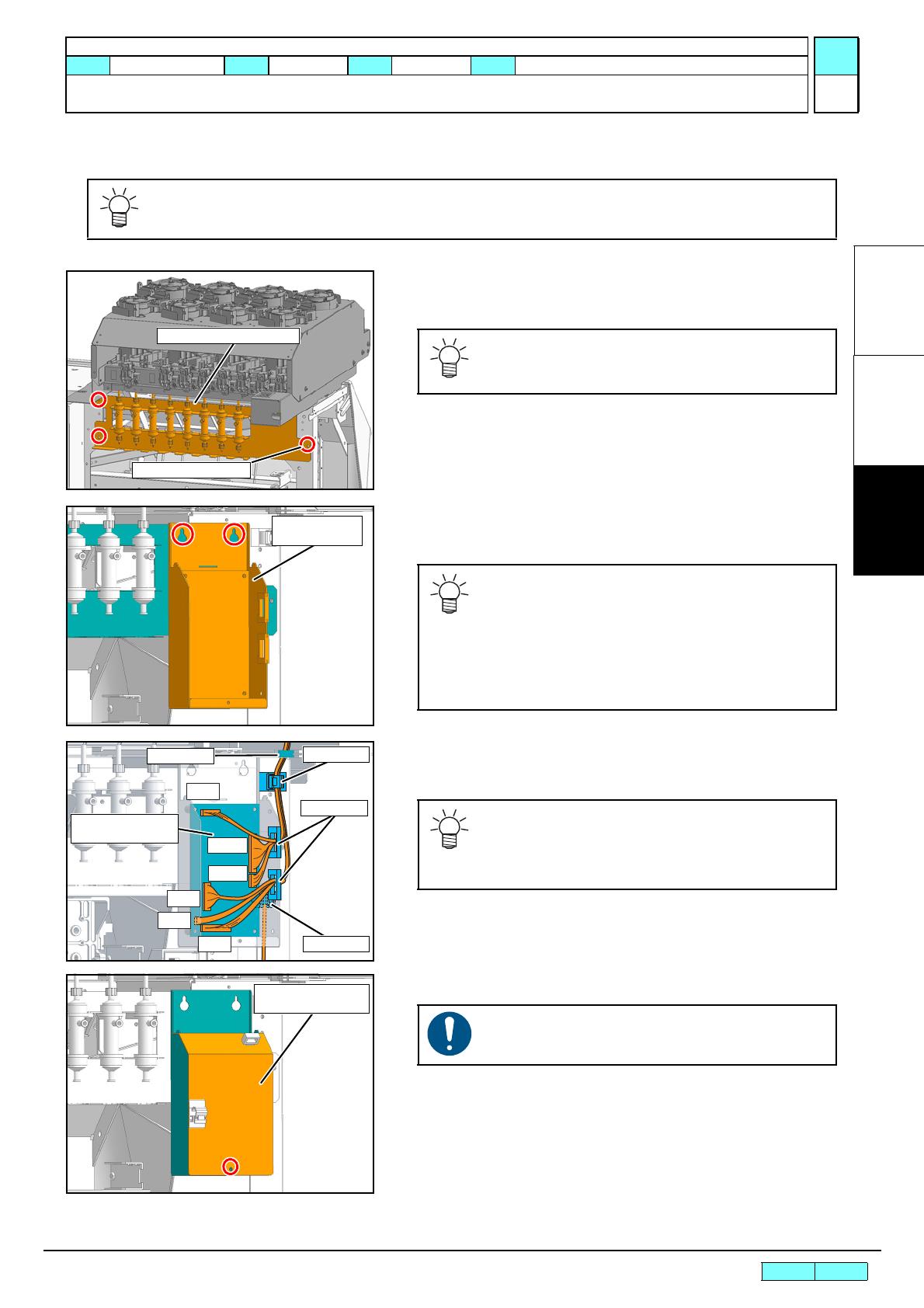
Connection with Ink supply attachment unit
1. Attach the Degassing module Assy. (P4*10SMW black
screw x3)
2. Install the Ink IO PCB Assy. together with the Ink IO PCB
BKT in the Degassing module Assy. (Screw x2)
3. Connect the connectors to CN3, CN5, CN6, Cn7, CN12 and
CN13 on the Ink IO PCB Assy.
4. Fix the cable with a clamp.
5. Attach the Ink IO PCB bracket cover. (Screw x1)
Installation of the Ink supply attachment unit refers to [OPT-J0476 Ink supply attachment unit
Installation Procedure Manual (D501433)]
Degassing module Assy.
Temporal fastening
Fasten temporarily the screws at the right of
backside which will be fastened together in the
STEP7.
As for the Ink IO PCB BKT and the Ink IO PCB
Assy., use the ones removed in the procedure
[OPT-J0476 Ink supply attachment unit Instal-
lation Procedure Manual (D501433)].
It is easy to work by attaching screws (x2) for
the twin hole to Degassing module Assy.
beforehand.
Ink IO PCB
Assy.
Clamp
Clamp
Clamp
Clamp
As for the CN3 and CN6, connect the cables of
the main unit.
Remaining cables are to be collected in the Ink
IO PCB BKT and clamped.
Be careful not to pinch the cables.


