Bosch GLM80 ユーザーマニュアル

カテゴリー
測定
タイプ
ユーザーマニュアル
Robert Bosch Power Tools GmbH
70538 Stuttgart
GERMANY
www.bosch-pt.com
1 609 92A 544 (2019.05) O / 72
en Original instructions
zh 正本使用
zh 原始使用說明書
ko 사용 설명서 원본
th หนังสือคู่มือการใช้งานฉบับ
ต้นแบบ
id Petunjuk-Petunjuk untuk Penggun-
aan Orisinal
vi Bn gc hướng dn s dng
1 609 92A 544
GLM Professional
80 | 80+R 60
2 |
English ...................................................Page 8
中文 ....................................................... 17
繁體中文.................................................. 26
한국어 ...............................................페이지 34
ไทย...................................................... หน้า 43
Bahasa Indonesia..................................... Halaman 53
Tiếng Vit............................................... Trang 62
1 609 92A 544 | (27.05.2019) Bosch Power Tools
| 3
GLM 250 VF
Professional
GLM 80
(j)(i)
(a)
(b)
(c)
(d)
(e)
(f)
(g)
(h)
(1)
(2)
(3)
(9)
(13)
(15)
(16)
(14)
(17)
(21)
(20)
(22)
(18)
(19)
(8)
(7)
(6)
(5)(4)
(10)
(11)
(12)
(23)
Bosch Power Tools 1 609 92A 544 | (27.05.2019)
4 |
1
XX
1
1
X
2
1
2
min
max
A
B C
DE
1 609 92A 544 | (27.05.2019) Bosch Power Tools
| 5
1
2
3
I
180º 90º 180º
F
H
G
I
(24) (24)
(25)
(3)
(2)
Bosch Power Tools 1 609 92A 544 | (27.05.2019)
6 |
180º
1
90º
180º
90º
J
K
I
1 609 92A 544 | (27.05.2019) Bosch Power Tools
| 7
1 608 M00 05B
0 601 079 000
2 607 001 391
BT 150
0 601 096 B00
(24)
(26) (27) (28)
Bosch Power Tools 1 609 92A 544 | (27.05.2019)
8 | English
English
Safety Instructions
All instructions must be
read and observed in order
for the measuring tool to
function safely. The safe-
guards integrated into the
measuring tool may be compromised if the measuring
tool is not used in accordance with these instructions.
Never make warning signs on the measuring tool unre-
cognisable. SAVE THESE INSTRUCTIONS FOR FUTURE
REFERENCE AND INCLUDE THEM WITH THE MEASURING
TOOL WHEN TRANSFERRING IT TO A THIRD PARTY.
uWarning! If operating or adjustment devices other
than those specified here are used or other proced-
ures are carried out, this can lead to dangerous expos-
ure to radiation.
The measuring tool is delivered with a warning label
(marked in the illustration of the measuring tool on the
graphics page with number (20)).
Laser Radiation
Do not stare into beam
Class 2 laser product
uIf the text on the warning label is not in your native
language, cover it with the label supplied, which is in
your language, before initial commissioning.
Do not direct the laser beam at persons or
animals and do not look directly into the
laser beam or at its reflection. Doing so
could lead to blindless, or could cause acci-
dents or damage to the eyes.
uIf laser radiation hits your eye, you must close your
eyes and immediately turn your head away from the
beam.
uDo not make any modifications to the laser equip-
ment.
uDo not use the laser goggles as protective goggles.
The laser goggles make the laser beam easier to see; they
do not protect you against laser radiation.
uDo not use the laser goggles as sunglasses or while
driving. The laser goggles do not provide full UV protec-
tion and impair your ability to see colours.
uHave the measuring tool serviced only by a qualified
specialist using only original replacement parts. This
will ensure that the safety of the measuring tool is main-
tained.
uDo not let children use the laser measuring tool unsu-
pervised. They could accidentally dazzle someone.
uDo not use the measuring tool in explosive atmo-
spheres which contain flammable liquids, gases or
dust. Sparks may be produced inside the measuring tool,
which can ignite dust or fumes.
Protect the measuring tool against heat,
e.g. including prolonged sun exposure, fire,
water, and moisture. Danger of explosion.
Product Description and
Specifications
Intended Use
The measuring tool is intended for measuring distances,
lengths, heights, clearances and inclines, and for calculating
areas and volumes.
The measuring tool is suitable for indoor and outdoor use.
Product features
The numbering of the product features refers to the diagram
of the measuring tool on the graphics page.
(1) Display
(2) Measuring button
(3) Button for grade measurement/calibrationA)
(4) Button for changing function/basic settingsA)
(5) Minus button
(6) Button for results/timer functionA)
(7) Button for list of measured values/saving constantA)
(8) Button for memory deletion/switching on or offA)
(9) Measuring pin
(10) Reference level selection button
(11) Plus button
(12) Button for distance, area and volume measurement
(13) Charging socket cover
(14) Socket for charging connector
(15) Carrying strap lug
(16) Laser beam output
(17) Reception lens
(18) Serial number
(19) 1/4" thread
(20) Laser warning label
(21) Charging connector
(22) Micro USB cable
(23) Protective bag
(24) Measuring railB)
(25) Locking lever for measuring barB)
1 609 92A 544 | (27.05.2019) Bosch Power Tools
English | 9
(26) TripodB)
(27) Laser viewing glassesB)
(28) Laser target plateB)
A) Press and hold a button to activate its additional function.
B) Accessories shown or described are not included with the
product as standard.
Display elements
(a) Measured value lines
(b) "ERROR" indicator
(c) Result line
(d) Digital spirit level/position of measured value list
entry
(e) Indicator for measured value list
(f) Measuring functions
Length measurement
Area measurement
Volume measurement
Continuous measurement
1
Indirect height measurement
1
2
Double indirect height measurement
1
Indirect length measurement
Timer function
Wall area measurement
Grade measurement
(g) Battery charge indicator
(h) Laser switched on
(i) Reference level of measurement
(j) Temperature warning
Technical data
Digital laser measure GLM 80 GLM 80+R 60
Article number 3 601 K72 3.. 3 601 K72 3..
Distance measurement
Measuring range (typical) 0.05–80mA) 0.05–80mA)
Measuring range (typical, unfavourable conditions) 35mB) 35m B)
Measuring accuracy (typical) ± 1.5mmA) ± 1.5mmA)
Measuring accuracy (typical, unfavourable conditions) ±2.5mmB) ±2.5mmB)
Smallest display unit 0.1mm 0.1mm
Indirect distance measurement and level
Measuring range –60° to +60° –60° to +60°
Grade measurement
Measuring range 0°–360° (4 x 90°)C) 0°–360° (4 x 90°)C)
Measuring accuracy (typical) 0.2°D) E) ±0.2°D) E)
Smallest display unit 0.1° 0.1°
General
Operating temperature -10°C to +50°CF) -10°C to +50°CF)
Storage temperature -20°C to +50°C -20°C to +50°C
Permitted charging temperature range +5°C to +40°C +5°C to +40°C
Relative air humidity max. 90% 90%
Max. altitude 2000 m 2000 m
Pollution degree according to IEC61010-1 2G) 2G)
Laser class 2 2
Laser type 635 nm, < 1mW 635 nm, < 1mW
Laser beam diameter (at 25°C) approx.
10m distance 6mmE) 6mmE)
80m distance 48mmE) 48mmE)
Adjustment accuracy of the laser to the housing approx.
– Vertical ±2mm/mH) ±2mm/mH)
– Horizontal ±10mm/mH) ±10mm/mH)
Bosch Power Tools 1 609 92A 544 | (27.05.2019)
10 | English
Digital laser measure GLM 80 GLM 80+R 60
Automatic switch-off after approx.
– Laser 20s 20s
Measuring tool (without measurement) 5min 5min
Weight according to EPTA-Procedure 01:2014 0.14kg 0.14kg
Dimensions 51 x 111 x 30mm 51 x 111 x 30mm
Protection rating IP 54 (dust and splash-proof) IP 54 (dust and splash-proof)
Measuring rail
Article number 3 601 K79 000
Dimensions 58 x 610 x 30mm
Battery Li-ion Li-ion
Rated voltage 3.7 V 3.7 V
Capacity 1.25 Ah 1.25 Ah
Number of battery cells 1 1
Individual measurements per battery charge approx. 25000I) 25000I)
A) For measurements from the front edge of the measuring tool, 100% reflectivity of the target (e.g. a white wall), weak backlighting and 25°C
operating temperature. In addition, a deviation influence of ± 0.05mm/m needs to be taken into account.
B) For measurements from the rear edge of the measuring tool, 10–100 % reflectivity of the target, strong backlighting and 25°C operating
temperature. In addition, a deviation influence of ± 0.29mm/m needs to be taken into account.
C) For measurements that use the back of the device as a reference, the max. measuring range amounts to ± 60°
D) After calibration in accordance with figure H. Additional pitch error of ± 0.01°/degree up to 45°.
E) The width of the laser line depends on the surface characteristics and on the ambient conditions.
F) In continuous measurement mode, the max. operating temperature is +40 °C.
G) Only non-conductive deposits occur, whereby occasional temporary conductivity caused by condensation is expected.
H) At 25°C
I) For a new and charged battery without display illumination and sound.
The serial number (18) on the type plate is used to clearly identify your measuring tool.
Assembly
Battery charging
The battery can be charged from a USB port or USB power
supply (min. 500mA) by using the micro USB cable.
Recommendations for optimal handling of the battery
Only store the battery in the permitted temperature range
(see "Technical data"). Do not leave the battery in your car in
the summer, for example.
A significantly reduced operating time after charging indic-
ates that the battery has deteriorated and must be replaced.
Follow the instructions on correct disposal.
Operation
Start-Up
uProtect the measuring tool from moisture and direct
sunlight.
uDo not expose the measuring tool to any extreme tem-
peratures or variations in temperature. For example,
do not leave it in a car for extended periods of time. In
case of large variations in temperature, allow the measur-
ing tool to adjust to the ambient temperature before put-
ting it into operation. The precision of the measuring tool
may be compromised if exposed to extreme temperat-
ures or variations in temperature.
uAvoid substantial knocks to the measuring tool and
avoid dropping it. Always carry out an accuracy check
before continuing work if the measuring tool has been
subjected to severe external influences (see "Checking
accuracy and calibrating the grade measurement (see fig-
ureH)", page14) and (see "Accuracy check of the dis-
tance measurement", page14).
Switching on/off
uNever leave the measuring tool unattended when
switched on, and ensure the measuring tool is
switched off after use. Others may be dazzled by the
laser beam.
The following options are available for switching on the
measuring tool:
Pressing the on/off button (8): The measuring tool is
switched on in the length measurement function. The
laser is not switched on.
Pressing the measuring button (2): Measuring tool and
laser are switched on. The measuring tool will be in the
length measurement function. When the measuring tool is
inserted in the measuring rail (24), the grade measure-
ment function is activated.
1 609 92A 544 | (27.05.2019) Bosch Power Tools
English | 11
uDo not direct the laser beam at persons or animals and
do not stare into the laser beam yourself (even from a
distance).
To switch off the measuring tool, press and hold the on/off
button (8).
If no button on the measuring tool is pressed for approx. five
minutes, then the measuring tool will automatically switch it-
self off to preserve battery life.
If the angle has not been changed for approx. five minutes
while the measuring tool is in the "grade measurement" oper-
ating mode, the tool will automatically switch itself off to pre-
serve battery life.
All saved values are retained when the tool is automatically
switched off.
Measuring process
After the measuring tool has been switched on by pressing
the measuring button (2), the tool is always in the length
measurement function by default, or in the grade measure-
ment function if the tool has been inserted into the measur-
ing rail (24). Other measuring functions can be switched to
by pressing the respective function button (see "Measuring
functions", page12).
Once the measuring tool has been switched on, the rear
edge of the measuring tool is selected as the reference level
for measurement. You can change the reference level by
pressing the reference level selection button(10) (see "Se-
lecting the reference level (see figureA)", page11).
Apply the measuring tool with the selected reference level to
the point at which you want to start the measurement (e.g.
wall).
To switch on the laser beam, briefly press the measuring but-
ton (2).
uDo not direct the laser beam at persons or animals and
do not stare into the laser beam yourself (even from a
distance).
Aim the laser beam at the target surface. To initiate the
measurement, briefly press the measuring button (2) again.
While the laser beam is continuously switched on, measure-
ment will begin after the first press of the measuring button
(2). In the continuous measurement function, measurement
begins as soon as the function is activated.
The measured value typically appears within 0.5 seconds
and no later than 4 seconds. The duration of the measure-
ment depends on the distance, the lighting conditions and
the reflective properties of the target surface. The end of the
measurement is indicated by an audio signal. Upon comple-
tion of the measurement, the laser beam is automatically
switched off.
If no measurement has been performed within approx.
20seconds of aim being taken, the laser beam is switched
off automatically to preserve battery life.
Selecting the reference level (see figureA)
You can choose between four different reference levels for
the measurement:
The rear edge of the measuring tool or the front edge of
the measuring pin (9) when it has been folded out by 90°
(e.g. when applying the tool to outer corners)
The tip of the measuring pin (9) when it has been folded
180° (e.g. when measuring from a corner)
The front edge of the measuring tool (e.g. when measur-
ing from a table edge)
The centre of the thread (19) (e.g. for tripod measure-
ments)
To select the reference level, press the button (10) until the
required reference level is shown on the display. The rear
edge of the measuring tool is pre-set as the reference level
every time the measuring tool is switched on.
It is not possible to make a retrospective alteration to the ref-
erence level for measurements that have already been taken
(e.g. when displaying measured values in the measured
value list).
Basic settings menu
To enter the basic settings menu, press and hold the button
for basic settings (4).
Briefly press the basic settings button (4) to select the indi-
vidual menu items.
Press the minus button (5) or the plus button (11) to select
the setting within the menu items.
To exit the basic settings menu, press the measuring button
(2).
Basic settings
Audio signals On
Off
Display illumination On
Off
Automatically
on/off
Digital spirit level On
Off
Display rotation On
Off
Continuous laser beam On
Off
Unit of distance (depending
on country version)
m, ft, inch, etc.
Bosch Power Tools 1 609 92A 544 | (27.05.2019)
12 | English
Basic settings
Unit for angle °, %, mm/m,
inch/ft
All basic settings except for the continuous laser beam set-
ting are saved when switching off the tool.
Continuous laser beam
uDo not direct the laser beam at persons or animals and
do not stare into the laser beam yourself (even from a
distance).
In this setting, the laser beam remains switched on even
between measurements; measurement simply requires one
brief press of the measuring button (2).
Measuring functions
Simple length measurement
For length measurements, repeatedly press the button (12)
until the indicator for length measurement appears on the
display.
Briefly press the measuring button (2) once to
switch on the laser and once to measure.
The measured value is displayed in the result
line (c).
For multiple consecutive length measurements, the results
of the last measurements are shown in the measured value
lines (a).
Area measurement
For area measurements, repeatedly press the button (12)
until the indicator for area measurement appears on the
display.
Then measure the width and length one after the other as
with a length measurement. The laser beam remains
switched on between the two measurements.
Once the second measurement has been com-
pleted, the area is automatically calculated and
displayed in the result line (c). The individual
measured values can be found in the measured
value lines (a).
Volume measurement
For volume measurements, repeatedly press the button
(12) until the indicator for volume measurement ap-
pears on the display.
Then measure the width, length and depth one after the
other as with a length measurement. The laser beam remains
switched on between the three measurements.
Once the third measurement has been com-
pleted, the volume is automatically calculated
and displayed in the result line (c). The indi-
vidual measured values can be found in the
measured value lines (a).
Values over 999,999m3 cannot be displayed; "ERROR" will
instead appear on the display. Divide the volume to be meas-
ured into individual measurements, the resulting values of
which you can calculate separately and then combine into an
overall total.
Continuous measurement and minimum/maximum
measurement (see figureB)
In continuous measurement mode, the measuring tool can
be moved relative to the target, during which the measured
value will be updated every half a second. You can, for ex-
ample, move a desired distance away from a wall while read-
ing off the current distance at all times.
For continuous measurements, repeatedly press the button
for changing function (4) until the indicator for continuous
measurement appears on the display. To start the continu-
ous measurement, press the measuring button (2).
The minimum measurement is used to determine the
shortest distance from a fixed reference point. For example,
it can help in determining verticals or horizontals.
The maximum measurement is used to determine the
greatest distance from a fixed reference point. For example,
it can help in determining diagonals.
The current measured value is shown in the
result line (c). The maximum ("max") and min-
imum ("min") measured value appear in the
measured value lines (a). It is then always
overwritten if the current length measurement
value is smaller or larger than the previous minimum or max-
imum value.
Press the memory deletion button (8) to erase the previous
minimum or maximum values.
Press the measuring button (2) to end the continuous meas-
urement. The last measured value is displayed in the result
line (c). Pressing the measuring button (2) again starts a
new continuous measurement.
Continuous measurement automatically switches off after
fiveminutes. The last measured value remains displayed in
the result line (c).
Indirect distance measurement
The indirect distance measurement is used to determine dis-
tances that cannot be measured directly, due to an obstacle
that would impede the path beam or the absence of a target
surface that could serve as a reflector. This measuring pro-
cedure can only be employed vertically. Any horizontal devi-
ation will lead to measurement errors.
The laser beam remains switched on between the individual
measurements.
For indirect length measurements, three measuring modes
are available. Each measuring mode can be used for determ-
ining different distances.
a) Indirect height measurement (see figureC)
Repeatedly press the button for changing function (4) until
the indicator for indirect height measurement
1
appears on
the display.
Ensure that the measuring tool is at the same height as the
lower measuring point. Then tilt the measuring tool around
the reference level and measure distance (1) as for a length
measurement.
1 609 92A 544 | (27.05.2019) Bosch Power Tools
English | 13
Once the measurement is complete, the result
for the required distance "X" is displayed in
the result line (c). The measured values for dis-
tance "1" and angle "α" can be found in the
measured value lines (a).
b) Double indirect height measurement (see figureD)
Repeatedly press the button for changing function (4) until
the indicator for double indirect height measurement
1
2
ap-
pears on the display.
Measure distances 1 and 2 in succession as for a length
measurement.
Once the measurement is complete, the result
for the required distance X is displayed in the
result row (c). The measured values for dis-
tances 1 and 2 and angle α can be found in the
measured value rows (a).
Ensure that the reference level for the measurement (e.g.
the rear edge of the measuring tool) remains in exactly the
same place for all the individual measurements in a single
measuring process.
c) Indirect length measurement (see figureE)
Repeatedly press the button for changing function (4) until
the indicator for indirect length measurement
1
appears on
the display.
Ensure that the measuring tool is at the same height as the
required measuring point. Then tilt the measuring tool
around the reference level and measure distance "1" as for a
length measurement.
Once the measurement is complete, the result
for the required distance "X" is displayed in
the result line (c). The measured values for dis-
tance "1" and angle "α" can be found in the
measured value lines (a).
Wall area measurement (see figureF)
The wall area measurement is used to determine the sum of
multiple individual areas with a common height.
In the illustrated example, the total area of several walls that
have the same ceiling height A but different lengths B is to
be determined.
For wall area measurements, repeatedly press the button for
changing function (4) until the indicator for wall area meas-
urement appears on the display.
Measure the ceiling height A as with a length measurement.
The measured value ("cst") is displayed in the top measured
value line (a). The laser remains switched on.
Then measure the length B1 of the first wall.
The area is automatically calculated and dis-
played in the result line (c). The last measured
value for length can be found in the middle
measured value line.(a). The laser remains
switched on.
Now measure the length B2 of the second wall.
The individual measured value displayed in the
middle measured value line (a) is added to the
length B1. The sum of the two lengths ("sum",
displayed in the bottom measured value line
(a)) is multiplied by the saved height A. The total area value
is displayed in the result line (c).
You can measure any number of lengths Bx, which will be
automatically added and multiplied by the height A.
The requirement for a correct area calculation is that the first
measured length (for example the ceiling height A) is
identical for all sub-areas.
Grade measurement (see figureG)
Press the button for grade measurement (3) to bring up the
indicator for grade measurement on the display. The rear
of the measuring tool serves as the reference level. Press the
button for grade measurement (3) again to use the sides of
the measuring tool as a reference level and rotate the display
view by 90°.
Press the measuring button (2) to fix the measured value
and transfer it to the measured value memory. Press the
measuring button (2) again to continue the measurement.
If the display flashes during measurement, the measuring
tool has been tipped too heavily to the side.
If the "digital spirit level" function is activated in the basic
settings, the grade value is also displayed in the other meas-
uring functions in line (d) of the display (1).
Timer function
The timer function is useful when the measuring tool should
be kept stationary during measurement, for example.
Press and hold the button for the timer function (6) to bring
up the indicator on the display.
The time period between triggering the timer and starting
measurement is displayed in the measured value line (a).
The time period can be set between 1–60 seconds by press-
ing the plus button (11) or minus button (5).
The measurement is made automatically after
the set time period has expired.
The timer function can also be used for dis-
tance measurements within other measuring
functions (e.g. area measurement). It is not possible to add
or subtract measuring results or carry out continuous meas-
urement.
List of the last measured values
The measuring tool stores the last 20 measured values and
their calculations and displays them in reverse order (with
the most recent measured value displayed first).
To retrieve the saved measurements, press the
button (7). The result of the last measurement
appears on the display, along with the indic-
ator for the measured values list (e) and with
storage space for the numbering of the dis-
played measurements.
If no further measurements are saved upon pressing the but-
ton (7) again, the measuring tool switches back to the last
Bosch Power Tools 1 609 92A 544 | (27.05.2019)
14 | English
measuring function. Press one of the buttons for the measur-
ing functions to exit the list of measured values.
To permanently save the currently displayed measured
length value as a constant, press and hold the button for the
list of measured values (7) until "CST" is shown on the dis-
play. An entry in the list of measured values cannot be retro-
spectively saved as a constant.
To use a measured length value in a measuring function (e.g.
area measurement), press the button for the list of meas-
ured values (7), select the desired entry and confirm it by
pressing the results button (6).
Deleting measured values
Briefly pressing the button (8) will delete the last measured
value in all measuring functions. Repeatedly pressing the
button briefly will delete the individual measured values in
reverse order.
To delete the currently displayed entry in the list of meas-
ured values, briefly press the button (8). To delete the com-
plete list of measured values and the constant "CST", press
and hold the measured value list button (7) and at the same
time briefly press the button (8).
In the wall area measurement function, a brief first press of
the button (8) will delete the last individual measured value;
a second press will delete all lengths BX; a third will delete
the ceiling height A.
Adding measured values
To add measured values together, first perform any meas-
urement or select an entry from the list of measured values.
Next, press the plus button (11). "+" will appear on the dis-
play as confirmation. Then perform a second measurement
or select another entry from the measured value list.
Press the results button (6) to retrieve the sum
of both measurements. The calculation is
shown in the measured value lines (a) and the
sum is displayed in the result line (c).
When the sum has been calculated, you can add more meas-
ured values or measured value list entries to this result if you
press the plus button (11) before each measurement. Press
the results button (6) to end the addition.
Information on addition:
Mixtures of length, area and volume values cannot be ad-
ded together. For example, if a length value and an area
value are added together, "ERROR" will appear briefly on
the display when the results button (6) is pressed. The
measuring tool will then switch back to the most recently
active measuring function.
The result of a measurement (e.g. volume value) is always
added; for continuous measurements, the measured
value displayed in the result line (c) is added. It is not
possible to add individual measured values from the
measured value lines (a).
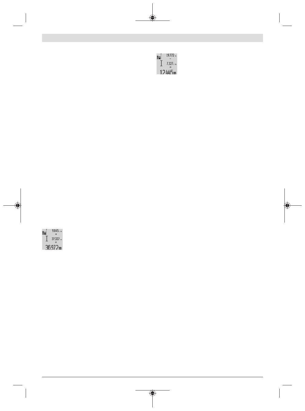
Subtracting measured values
To subtract measured values, press the minus
button (5); "-" will appear on the display as
confirmation. The subsequent steps are the
same as for the "Adding measured values" sec-
tion.
Practical advice
General advice
The reception lens (17) and the laser beam output (16)
must not be covered during the measuring process.
The measuring tool must not be moved during a measure-
ment (with the exception of the continuous measurement
and grade measurement functions). For this reason, place
the measuring tool against or on a firm surface whenever
possible.
Influences on the measuring range
The measuring range depends on the lighting conditions and
the reflective properties of the target surface. For better vis-
ibility of the laser beam when working outdoors and in bright
sunlight, use the laser viewing glasses (27) (accessory) and
the laser target plate (28) (accessory) or shade the target
area.
Influences on the measurement result
Due to physical effects, the possibility of inaccurate meas-
urements when measuring various surfaces cannot be ex-
cluded. These include:
Transparent surfaces (e.g. glass, water)
Reflective surfaces (e.g. polished metal, glass)
Porous surfaces (e.g. insulating materials)
Structured surfaces (e.g. roughcast, natural stone).
If necessary, use the laser target plate (28) (accessory) on
these surfaces.
Inaccurate measurements are also possible where the laser
is pointed at target surfaces diagonally.
Layers of air at different temperatures and indirectly re-
ceived reflections can also influence the measured value.
Checking accuracy and calibrating the grade
measurement (see figureH)
Regularly check the accuracy of the grade measurement.
This is accomplished by means of a reverse measurement.
To do this, lay the measuring tool on a table and measure the
inclination. Turn the measuring tool by 180° and measure
the inclination again. The difference between the displayed
values must not exceed 0.3°.
In case of greater deviation, the measuring tool must be re-
calibrated. To do this, press and hold the grade measure-
ment button (3). Follow the directions on the display.
Accuracy check of the distance measurement
You can check the accuracy of the measuring tool as follows:
Choose a measuring section of approx. 1–10 m in length
that is permanently unchanged, the exact length of which
is known to you (e.g. room width, door opening). The
measuring section must be indoors, and the target sur-
1 609 92A 544 | (27.05.2019) Bosch Power Tools
English | 15
face of the measurement must be smooth and reflect
well.
Measure the section ten times in succession.
The deviation between the individual measurements and the
mean value must not exceed ± 2mm. Record the measure-
ments in order to be able to compare the accuracy later on.
Working with the tripod (accessory)
The use of a tripod is particularly necessary for larger dis-
tances. Place the measuring tool with the 1/4" thread (19)
on the quick-release plate of the tripod (26) or a conven-
tional camera tripod. Tighten it using the locking screw of the
quick-release plate.
Set the reference level for measurements with a tripod by
pressing the button (10) accordingly (thread reference
level).
Working with the measuring rail (see figuresI–K)
The measuring rail (24) can be used for a more exact grade
measurement result. Distance measurements are not pos-
sible with the measuring rail.
Insert the measuring tool into the measuring
rail (24) as shown and lock the measuring tool
in place with the locking lever (25). Press the
measuring button (2) to activate the "measur-
ing rail" operating mode.
Regularly check the accuracy of the grade measurement by
means of a reverse measurement or the levels on the meas-
uring rail.
In case of greater deviation, the measuring tool must be re-
calibrated. To do this, press and hold the grade measure-
ment button (3). Follow the directions on the display.
To end the "measuring rail" operating mode, switch off the
measuring tool and remove it from the measuring rail.
Errors – Causes and Corrective Measures
Cause Corrective measures
Temperature warning(j) flashes, measurement not pos-
sible.
The measuring tool is outside
the operating temperature of
–10 °C to +50 °C (in the con-
tinuous measurement func-
tion, up to +40 °C).
Wait until the measuring tool
has reached operating tem-
perature.
Display shows "ERROR"
Addition/subtraction of
measured values with differ-
ent units of measurement.
Only add/subtract measured
values with the same units of
measurement.
Angle between laser beam
and target is too acute.
Increase the angle between
the laser beam and the target
Target surface is too reflect-
ive (e.g. mirror) or not re-
flective enough (e.g. black
material), or ambient light is
too bright.
Use the laser target plate
(28).
Cause Corrective measures
The laser beam output (16)
and/or reception lens (17)
are fogged up (e.g. due to a
rapid temperature change).
Wipe the laser beam output
(16) and/or reception lens
(17) dry with a soft cloth.
Calculated value is larger
than 999,999m/m2/m3.
Divide the calculation into in-
termediate steps.
Display shows "> 60°" or "< –60°"
The grade measuring range
for the measuring function or
reference level has been ex-
ceeded.
Perform the measurements
within the specified angle
range.
Display shows "CAL" and "ERROR"
The calibration of the grade
measurement has not been
carried out in the right order
or has not been carried out in
the correct positions.
Repeat the calibration ac-
cording to the instructions
that appear on the display
and in the manual.
The surfaces used for calib-
ration were not precisely ho-
rizontal or vertical.
Repeat the calibration on a
horizontal or vertical surface
and check the surfaces be-
forehand if necessary using a
spirit level.
The measuring tool has
moved or tilted when the
button was pressed.
Repeat the calibration and
hold the measuring tool still
against the surface when
pressing the button.
Battery charge indicator (g), temperature warning (j)
and "ERROR" shown in the display
The temperature of the
measuring tool is outside the
permissible charging temper-
ature range.
Wait until the charging tem-
perature range has been
reached.
Battery charge indicator (g) and "ERROR" shown in the
display
The battery charging voltage
is not correct.
Check whether the connec-
tion has been established
correctly and that the micro
USB cable is working prop-
erly. If the device symbol
flashes, the battery is defect-
ive and must be replaced by
the Bosch after-sales ser-
vice.
Battery charge indicator (g) and clock symbol (f) shown
in the display
Charging time significantly
extended due to the charging
current being too low.
Only use the original Bosch
micro USB cable.
Measurement result implausible
Target surface reflection not
distinct (e.g. water, glass).
Cover the target surface.
Bosch Power Tools 1 609 92A 544 | (27.05.2019)
16 | English
Cause Corrective measures
Laser beam output (16) and/
or reception lens (17) are
covered.
Keep the laser beam output
(16) and/or reception lens
(17) clear.
An incorrect reference level
has been set.
Select a reference level that
is appropriate for the meas-
urement.
Obstruction in the path of the
laser beam.
The laser point must be fully
on the target surface.
The indicator remains unchanged or the measuring tool
reacts unexpectedly when a button is pressed.
Software error. Press the measuring button
(2) and the button for
memory deletion/switching
on or off (8) to reset the soft-
ware.
The measuring tool monitors correct function-
ing in every measurement. If a defect is detec-
ted, the display will indicate only the symbol
shown opposite. In this case, or if the above-
mentioned corrective measures cannot rectify
an error, submit the measuring tool to the Bosch after-sales
service via your dealer.
Maintenance and Service
Maintenance and Cleaning
Only store and transport the measuring tool in the protective
bag provided.
Keep the measuring tool clean at all times.
Never immerse the measuring tool in water or other liquids.
Wipe off any dirt using a damp, soft cloth. Do not use any de-
tergents or solvents.
Take particular care of the reception lens (17), which must
be handled with the same level of care you would give to a
pair of glasses or a camera lens.
If the measuring tool needs to be repaired, send it off in the
protective bag (23).
After-Sales Service and Application Service
Our after-sales service responds to your questions concern-
ing maintenance and repair of your product as well as spare
parts. You can find explosion drawings and information on
spare parts at: www.bosch-pt.com
The Bosch product use advice team will be happy to help you
with any questions about our products and their accessor-
ies.
In all correspondence and spare parts orders, please always
include the 10‑digit article number given on the nameplate
of the product.
Great Britain
Robert Bosch Ltd. (B.S.C.)
P.O. Box 98
Broadwater Park
North Orbital Road
Denham Uxbridge
UB 9 5HJ
At www.bosch-pt.co.uk you can order spare parts or arrange
the collection of a product in need of servicing or repair.
Tel. Service: (0344) 7360109
Ireland
Origo Ltd.
Unit 23 Magna Drive
Magna Business Park
City West
Dublin 24
Tel. Service: (01) 4666700
Fax: (01) 4666888
Australia, New Zealand and Pacific Islands
Robert Bosch Australia Pty. Ltd.
Power Tools
Locked Bag 66
Clayton South VIC 3169
Customer Contact Center
Inside Australia:
Phone: (01300) 307044
Fax: (01300) 307045
Inside New Zealand:
Phone: (0800) 543353
Fax: (0800) 428570
Outside AU and NZ:
Phone: +61 3 95415555
www.bosch-pt.com.au
www.bosch-pt.co.nz
Republic of South Africa
Customer service
Hotline: (011) 6519600
Gauteng – BSC Service Centre
35 Roper Street, New Centre
Johannesburg
Tel.: (011) 4939375
Fax: (011) 4930126
KZN – BSC Service Centre
Unit E, Almar Centre
143 Crompton Street
Pinetown
Tel.: (031) 7012120
Fax: (031) 7012446
Western Cape – BSC Service Centre
Democracy Way, Prosperity Park
Milnerton
Tel.: (021) 5512577
Fax: (021) 5513223
Bosch Headquarters
Midrand, Gauteng
Tel.: (011) 6519600
Fax: (011) 6519880
1 609 92A 544 | (27.05.2019) Bosch Power Tools
中文 | 17
Armenia, Azerbaijan, Georgia
Robert Bosch Ltd.
David Agmashenebeli ave. 61
0102 Tbilisi, Georgia
Tel. +995322510073
www.bosch.com
Kyrgyzstan, Mongolia, Tajikistan, Turkmenistan,
Uzbekistan
TOO “Robert Bosch” Power Tools, After Sales Service
Muratbaev Ave., 180
050012, Almaty, Kazakhstan
Service Email: [email protected]
Official Website: www.bosch.com, www.bosch-pt.com
Disposal
Measuring tools, rechargeable/non-rechargeable
batteries, accessories and packaging should be
sorted for environmental-friendly recycling.
Do not dispose of the measuring tools or re-
chargeable/non-rechargeable batteries with
household waste.
Battery packs/batteries:
Li-ion:
Please observe the notes in the section on transport Trans-
port.
uIntegrated batteries may only be removed for disposal
by qualified personnel. Opening the housing shell can
destroy the measuring tool.
Before you can remove the battery from the measuing tool,
you will need to use the measuring tool until the battery is
completely discharged. Unscrew the screws on the housing
and remove the housing shell in order to remove the battery.
To prevent a short circuit, disconnect the connectors on the
battery one at a time and then isolate the poles. Even when
fully discharged, the battery still contains a residual capa-
city, which can be released in case of a short circuit.
中文
安全规章
必须阅读并注意所有说
明,从而安全可靠地操作
测量仪。如果不按照给出
的说明使用测量仪,可能
会影响集成在测量仪中的保护功能。测量仪上的警
戒牌应保持清晰可读的状态。请妥善保存本说明
书,并在转交测量仪时将本说明书一起移交。
u小心 – 如果使用了与此处指定的操作或校准设备
不同的设备,或执行了不同的过程方法,可能会
导致危险的光束泄露。
交付的测量仪带有一块警戒牌(在图形页的测量仪
示意图中用编号 (20) 标记)。
Laser Radiation
Do not stare into beam
Class 2 laser product
u如果警戒牌的文字并非贵国语言,使用仪器之
前,先把附带的以贵国语言书写的的贴纸贴在警
戒牌上。
不得将激光束指向人或动物,请勿直视
激光束或反射的激光束。 可能会致人炫
目、引发事故或损伤眼睛。
u如果激光束射向眼部,必须有意识地闭眼,立即
从光束位置将头移开。
u请不要对激光装置进行任何更改。
u激光视镜不得用作护目镜。激光视镜用于更好地
识别激光束;然而对激光束并没有防护作用。
u激光视镜不得用作太阳镜或在道路交通中使用。
激光视镜并不能完全防护紫外线,还会干扰对色
彩的感知。
u仅允许由具备资质的专业人员使用原装备件修理
测量仪。如此才能够确保测量仪的安全性能。
u不得让儿童在无人看管的情况下使用激光测量
仪。可能意外地让人炫目
u请勿在有易燃液体、气体或粉尘的潜在爆炸性环
境中使用测量仪。测量仪器内可能产生火花并点
燃粉尘和气体。
保护测量工具 免受高温(例如长期日
照)、火焰、水和湿气的侵害。 有爆炸
的危险。
Bosch Power Tools 1 609 92A 544 | (27.05.2019)
18 | 中文
产品和性能说明
按照规定使用
本测量仪用于测量距离、长度、高度、间距和倾角
以及用于计算面积和体积。
本测量仪适合在室内和室外使用。
插图上的机件
机件的编号和仪器详解图上的编号一致。
(1) 显示屏
(2) 测量按键
(3) 倾斜度测量/校准按键A)
(4) 功能转换/基本设置按键A)
(5) 减号键
(6) 结果/计时器功能按键A)
(7) 测量值列表/常数存储按键A)
(8) 存储器删除按键/开关键A)
(9) 止动销
(10) 选择基准面
(11) 加号键
(12) 长度、面积和体积测量按键
(13) 充电插座的盖子
(14) 充电插头的插口
(15) 拎环固定座
(16) 激光束出口
(17) 接收透镜
(18) 序列号
(19) 1/4英寸螺纹
(20) 激光警戒牌
(21) 充电插头
(22) Micro USB电缆
(23) 保护袋
(24) 测量轨B)
(25) 测量轨锁定杆B)
(26) 三脚架B)
(27) 激光护目镜B)
(28) 激光靶B)
A) 按住按键以调用扩展功能。
B) 图表或说明上提到的附件,并不包含在基本的供货范围
中。
显示元件
(a) 测量值行
(b) 错误显示“Error”
(c) 测量结果行
(d) 数字水准仪/测量值列表条目的位置
(e) 测量值列表指示器
(f) 测量功能
长度测量
面积测量
体积测量
持续测量
1
间接高度测量
1
2
双重间接高度测量
1
间接长度测量
计时器功能
墙壁面积测量
倾斜度测量
(g) 充电电池电量指示灯
(h) 激光已接通
(i) 测量的基准面
(j) 温度警告
技术参数
数字式激光测距仪 GLM 80 GLM 80+R 60
物品代码 3 601 K72 3.. 3 601 K72 3..
距离测量
测量范围(典型) 0.05-80A) 0.05-80A)
测量范围(一般,不利的条件) 35B) 35B)
测量精度(典型) ±1.5毫米A) ±1.5毫米A)
测量精度(一般,不利的条件) ±2.5毫米B) ±2.5毫米B)
1 609 92A 544 | (27.05.2019) Bosch Power Tools
中文 | 19
数字式激光测距仪 GLM 80 GLM 80+R 60
最小显示单位 0.1毫米 0.1毫米
间接距离测量和水准仪
测量范围 –60度至+60–60度至+60
倾斜度测量
测量范围 0–360度(4x90度)C) 0–360度(4x90度)C)
测量精度(典型) 0.2D)E) ±0.2D)E)
最小显示单位 0.10.1
常规
工作温度 –10摄氏度至+50摄氏度F) –10摄氏度至+50摄氏度F)
仓储温度 –20摄氏度至+50摄氏度 –20摄氏度至+50摄氏度
许可的充电温度范围 +5摄氏度至+40摄氏度 +5摄氏度至+40摄氏度
最大相对空气湿度 90 % 90 %
基准高度以上的最大使用高度 20002000
脏污程度符合IEC61010-1 2G) 2G)
激光等级 2 2
激光种类 635纳米,< 1毫瓦 635纳米,< 1毫瓦
激光束直径(在25摄氏度时)约
– 距离10米远 6毫米E) 6毫米E)
– 距离80米远 48毫米E) 48毫米E)
针对机壳的激光调节精度约
– 垂直 ±2毫米/H) ±2毫米/H)
– 水平 ±10毫米/H) ±10毫米/H)
自动断开时间约
– 激光 2020
– 测量仪(不测量) 55
重量符合EPTA-Procedure 01:2014 0.14公斤 0.14公斤
尺寸 51 x 111 x 30毫米 51 x 111 x 30毫米
防护类型 IP 54(防尘、防溅) IP 54(防尘、防溅)
测量轨
物品代码 3 601 K79 000
尺寸 58 x 610 x 30毫米
充电电池 锂离子 锂离子
额定电压 3.73.7
电量 1.25安培小时 1.25安培小时
充电电池单元数量 1 1
Bosch Power Tools 1 609 92A 544 | (27.05.2019)
20 | 中文
数字式激光测距仪 GLM 80 GLM 80+R 60
每次充电后的单次测量数约 25000I) 25000I)
A) 在从测量仪的前缘起测量、目标有100%的反射能力(例如涂刷的白色墙壁)、背景照明暗且工作温度为25摄氏度时。
此外要考虑±0.05毫米/米的影响。
B) 在从测量仪的后缘起测量、目标有10 –100%的反射能力、背景照明亮且工作温度为25摄氏度时。此外要考虑±0.29毫
米/米的影响。
C) 如果以设备背面为基准测量,则最大测量范围为±60度
D) 按照图示H校准后。额外的螺距误差±0.01度/至45度。
E) 激光线的宽度取决于表面特性和环境条件。
F) 在持续测量功能中,最大工作温度为+40摄氏度。
G) 仅出现非导电性污染,不过有时会因凝结而暂时具备导电性。
H) 在25摄氏度时
I) 针对新的和已充满电的充电电池,在未使用显示屏照明和声音信号的情况下。
型号铭牌上的序列号(18)用于准确识别您的测量仪。
安装
为充电电池充电
可以通过USB接口或USB电源(最小500毫安)用
Micro USB电缆给充电电池充电。
如何正确地使用充电电池
充电电池只能存放在允许的温度范围内,参见“技术
参数”。夏天不得将充电电池搁置在汽车中。
充电后如果充电电池的使用时间明显缩短,代表充
电电池已经损坏,必须更换新的充电电池。
请注意有关废弃处理的规定。
工作
投入使用
u不可以让湿气渗入仪器中,也不可以让阳光直接
照射在仪器上。
u请勿在极端温度或温度波动较大的情况下使用测
量仪。比如请勿将测量仪长时间放在汽车内。温
度波动较大的情况下,使用测量仪之前先使其温
度稳定下来。在极端温度或温度波动较大的情况
下,测量仪的精度可能会受到影响。
u避免让测量仪发生剧烈碰撞或使其掉落。 测量仪
受到强烈的外部影响后,在继续工作前务必进行
一次精度检查 (参见 “倾斜度测量的精度检查和校
准(参见插图H)”, 页24)和(参见 “距离测量精
度检查”, 页24)。
接通/关闭
u测量仪接通后应有人看管,使用后应关闭。激光
可能会让旁人炫目。
可采用以下方式接通测量仪:
– 按压开关键(8):测量仪接通并且处于长度测量功
能中。激光器不接通。
– 按下测量按键(2):测量仪和激光器被接通。测量
仪处于长度测量功能中。对于安装在测量轨(24)
上的测量仪,倾斜度测量功能已激活。
u不得将激光束对准人或动物,也请勿直视激光
束,即使和激光束相距甚远也不可以做上述动
作。
如要关闭测量仪,长按开关键(8)
如果在约5分钟的时间内没有按下测量仪上的任何按
键,测量仪便会自动关闭,以保护充电电池。
如果在运行模式“倾斜度测量”中,角度约5分钟不变
化,测量仪便会自动关闭,以保护充电电池。
在自动关机后,所有储存的测量值被保留。
测量过程
按下测量按键(2)接通测量仪后,如果测量仪是安装
在测量轨(24)上,便会始终处于长度测量或倾斜度测
量模式下。可以按下相应的功能键调到其他测量功
能 (参见 “测量功能”, 页21)。
开机后的测量基准面已选为测量仪的后缘。按下基
准面按键(10)可以更改基准面 (参见 “选择基准面
(参见插图A)”, 页21).
将测量仪的所选基准面置于所需的测量起始点上
(如墙壁)。
如要接通激光束,请短促按压测量按键(2)
u不得将激光束对准人或动物,也请勿直视激光
束,即使和激光束相距甚远也不可以做上述动
作。
将激光束瞄准目标面。启动测量时,请再次短促按
压测量按键(2)
如永久性激光束已接通,则第一次按下测量按键(2)
后便会开始测量。如果选择持续测量功能,只要一
启动这个功能便可以进行测量。
测量值通常在0.5秒最晚4秒后出现。测量时长取决
于距离、照明条件和目标面的反射特性。在测量结
1 609 92A 544 | (27.05.2019) Bosch Power Tools
  • Page 1 1
  • Page 2 2
  • Page 3 3
  • Page 4 4
  • Page 5 5
  • Page 6 6
  • Page 7 7
  • Page 8 8
  • Page 9 9
  • Page 10 10
  • Page 11 11
  • Page 12 12
  • Page 13 13
  • Page 14 14
  • Page 15 15
  • Page 16 16
  • Page 17 17
  • Page 18 18
  • Page 19 19
  • Page 20 20
  • Page 21 21
  • Page 22 22
  • Page 23 23
  • Page 24 24
  • Page 25 25
  • Page 26 26
  • Page 27 27
  • Page 28 28
  • Page 29 29
  • Page 30 30
  • Page 31 31
  • Page 32 32
  • Page 33 33
  • Page 34 34
  • Page 35 35
  • Page 36 36
  • Page 37 37
  • Page 38 38
  • Page 39 39
  • Page 40 40
  • Page 41 41
  • Page 42 42
  • Page 43 43
  • Page 44 44
  • Page 45 45
  • Page 46 46
  • Page 47 47
  • Page 48 48
  • Page 49 49
  • Page 50 50
  • Page 51 51
  • Page 52 52
  • Page 53 53
  • Page 54 54
  • Page 55 55
  • Page 56 56
  • Page 57 57
  • Page 58 58
  • Page 59 59
  • Page 60 60
  • Page 61 61
  • Page 62 62
  • Page 63 63
  • Page 64 64
  • Page 65 65
  • Page 66 66
  • Page 67 67
  • Page 68 68
  • Page 69 69
  • Page 70 70
  • Page 71 71

Bosch GLM80 ユーザーマニュアル

カテゴリー
測定
タイプ
ユーザーマニュアル