Lantronix Lantronix SLB: Branch Office Manager クイックスタートガイド
- タイプ
- クイックスタートガイド

WHAT’S
INSIDE
SLB
Quick Start Guide
1 HARDWARE REVIEW
WHAT’S
INSIDE
SLB
Quick Start Guide
1 HARDWARE REVIEW
WHAT’S
INSIDE
SLB
Quick Start Guide
1 HARDWARE REVIEW
SLB Branch Of ce Manager Quick Start Guide
Power Cords
Included power cords vary for kit purchased. Please see www.lantronix.com for
additional inlet power cords available.
AC Voltage Kit Part Number Power Cord Description
(50/60 Hz)
100-120V SLB882KIT-15P SLPP12310-01 Inlet cord: IEC60320/C19
to NEMA 5-15P (15A)
100-120V SLB882KIT-20P SLPP12410-01 Inlet cord: IEC60320/C19
to NEMA 5-20P (20A)
200-240V SLB8824KIT-EU SLPP12810-01 Inlet cord: IEC60320/C19
to Schuko (EU)
SLPP12910-01 Inlet cord: IEC60320/C19
to BS1363 (UK)
200-240V SLB8824KIT-AP SLPP12A08-01 IEC60320/C19 to AS/NZS
3112 (AU/NZ)
SLPP12C08-01 IEC60320/C19 to CHINA/
GB (CN)
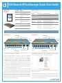
The SLB is a hybrid console manager and power manager in the form
of a space saving 19” 1RU design.
The SLB connects between a server or a piece of IT equipment and
an IP network or the Internet. Once installed on the IP network,
a remote user connects to the SLB using a secure web browser
(HTTPS/SSL), Secure Shell (SSH), or Telnet session. If a modem is
used in the SLB, dial-in access is possible in the event that the IP
network is unavailable. Once connected, the user has access to
the server or IT equipment’s command line interface (CLI) via the
console port to perform maintenance or management tasks. If the
equipment is connected to one of the SLB power outlets, then
(on/off/reboot) power control is possible.
The front LCD panel and keypad allows for quick and easy network
configuration. The front panel console port allows a dumb terminal
or PC with terminal emulation software to locally access manage-
ment functions and connected serial console devices. The device
ports allow simple connections to serial devices using adapters and
a standard Cat-5 cable. Connect one end of the Cat-5 cable to the
device port, and the other end to an adapter that attaches to the
serial console of the target system.
For example, to connect a PC to the device port of the SLB, you only
need the female DB9 adapter (Part #200.2070A) and a standard
Cat-5 cable, both of which are supplied with the SLB.
The default communication parameters for the device ports and the
console port are:
• 9600 baud • 8 data bits • No parity • 1 stop bit • No flow control
The power outlets allow your equipment to use the SLB as its power
source. Once connected you can remotely and securely control the
state of each outlet (on/off/reboot).
Accessories Included
Part Number Description
200.2066A Adapter: RJ45 to DB25M (DCE)
for Sun with DB25 female
200.2067A Adapter: RJ45 to DB25F (DCE)
for Sun with DB25 male and
some HP9000’s
200.2069A Adapter: RJ45 to DB9M (DCE) for
SGI Onyx
200.2070A Adapter: RJ45 to DB9F (DCE)
for HP9000, SGI Origin, IBM
RS6000,and PC-based Unix/
Linux servers
ADP010104-01 Adapter: RJ45 Rolled serial, 0.1m
(0.33 Ft.) for Cisco and Sun Netra
200.0063 Cable: RJ45 to RJ45, Cat-5, 2m
(6.6 Ft.)
500-153 Cable:RJ45 Loopback
Secondary AC Inlet
Modem
USB Port
Device ports 1-8
Console Port
10/100
Dual Ethernet
ports
Primary AC Inlet
KeypadLCD
Front View
110-120V AC 200-240V AC
Back View
Power outlets 1-8
Modem
USB Port
Secondary AC Inlet
Modem
USB Port
Device ports 1-8
Console Port
10/100
Dual Ethernet
ports
Primary AC Inlet
KeypadLCD
Front View
Back View
Power outlets 1-8
SLB Branch Of ce Manager Quick Start Guide
Power Cords Included
Included power cords vary for kit purchased. Please see www.lantronix.com for
additional inlet power cords available.
SLB Part #
Power Cord Part #
Power Cord Description Quantity
100-120 VAC (50/60 Hz)
SLB882KIT-15P SLPP12310-01 IEC60320/C19 to NEMA 5-15P (15A) 2
SLB882KIT-20P SLPP12410-01 IEC60320/C19 to NEMA 5-20P (20A) 2
200-240 VAC (50/60 Hz)
SLB8824KIT-EU SLPP12810-01 IEC60320/C19 to Schuko (EU) 2
SLPP12910-01 EC60320/C19 to BS1363 (UK) 2
SLB8824KIT-AP SLPP12A08-01 IEC60320/C19 to AS/NZS 3112 (AU/NZ) 2
SLPP12C08-01 IEC60320/C19 to CHINA/GB (CN) 2
SLB8824KIT-WW SLPP12810-01 IEC60320/C19 to Schuko (EU) 1
SLPP12910-01 EC60320/C19 to BS1363 (UK) 1
SLPP12A08-01 IEC60320/C19 to AS/NZS 3112 (AU/NZ) 1
SLPP12C08-01 IEC60320/C19 to CHINA/GB (CN) 1
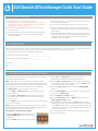
The SLB is a hybrid console manager and power manager in the form
of a space saving 19” 1RU design.
The SLB connects between a server or a piece of IT equipment and
an IP network or the Internet. Once installed on the IP network,
a remote user connects to the SLB using a secure web browser
(HTTPS/SSL), Secure Shell (SSH), or Telnet session. If a modem is
used in the SLB, dial-in access is possible in the event that the IP
network is unavailable. Once connected, the user has access to
the server or IT equipment’s command line interface (CLI) via the
console port to perform maintenance or management tasks. If the
equipment is connected to one of the SLB power outlets, then
(on/off/reboot) power control is possible.
The front LCD panel and keypad allows for quick and easy network
configuration. The front panel console port allows a dumb terminal
or PC with terminal emulation software to locally access manage-
ment functions and connected serial console devices. The device
ports allow simple connections to serial devices using adapters and
a standard Cat-5 cable. Connect one end of the Cat-5 cable to the
device port, and the other end to an adapter that attaches to the
serial console of the target system.
For example, to connect a PC to the device port of the SLB, you only
need the female DB9 adapter (Part #200.2070A) and a standard
Cat-5 cable, both of which are supplied with the SLB.
The default communication parameters for the device ports and the
console port are:
•9600baud•8databits•Noparity•1stopbit•Noflowcontrol
The power outlets allow your equipment to use the SLB as its power
source. Once connected you can remotely and securely control the
state of each outlet (on/off/reboot).
Accessories Included
Part Number Description
200.2066A Adapter: RJ45 to DB25M (DCE)
for Sun with DB25 female
200.2067A Adapter: RJ45 to DB25F (DCE)
for Sun with DB25 male and
some HP9000’s
200.2069A Adapter: RJ45 to DB9M (DCE) for
SGI Onyx
200.2070A Adapter: RJ45 to DB9F (DCE)
for HP9000, SGI Origin, IBM
RS6000,and PC-based Unix/
Linux servers
ADP010104-01 Adapter: RJ45 Rolled serial, 0.1m
(0.33 Ft.) for Cisco and Sun Netra
200.0063 Cable: RJ45 to RJ45, Cat-5, 2m
(6.6 Ft.)
500-153 Cable:RJ45 Loopback
Secondary AC Inlet
Modem
USB Port
Device ports 1-8
Console Port
10/100
Dual Ethernet
ports
Primary AC Inlet
KeypadLCD
Front View
100-120V AC 200-240V AC
Back View
Power outlets 1-8
Modem
USB Port
Secondary AC Inlet
Modem
USB Port
Device ports 1-8
Console Port
10/100
Dual Ethernet
ports
Primary AC Inlet
KeypadLCD
Front View
Back View
Power outlets 1-8
SLB Branch Oce Manager Quick Start Guide
Power Cords Included
Included power cords vary for kit purchased. Please see www.lantronix.com for additional
inlet power cords available.
SLB Part #
Power Cord Part #
Power Cord Description Quantity
100-120 VAC (50/60 Hz)
SLB882KIT-15P SLPP12310-01 IEC60320/C19 to NEMA 5-15P (15A) 2
SLB882KIT-20P SLPP12410-01 IEC60320/C19 to NEMA 5-20P (20A) 2
200-240 VAC (50/60 Hz)
SLB8824KIT-EU SLPP12810-01 IEC60320/C19 to Schuko (EU) 2
SLPP12910-01 IEC60320/C19 to BS1363 (UK) 2
SLB8824KIT-AP SLPP12A08-01 IEC60320/C19 to AS/NZS 3112 (AU/NZ) 2
SLPP12C08-01 IEC60320/C19 to CHINA/GB (CN) 2
SLB8824KIT-WW SLPP12810-01 IEC60320/C19 to Schuko (EU) 1
SLPP12910-01 IEC60320/C19 to BS1363 (UK) 1
SLPP12A08-01 IEC60320/C19 to AS/NZS 3112 (AU/NZ) 1
SLPP12C08-01 IEC60320/C19 to CHINA/GB (CN) 1
The SLB is a hybrid console manager and power manager in the
form of a space saving 19” 1RU design.
The SLB connects between a server or a piece of IT equipment
and an IP network or the Internet. Once installed on the IP network,
a remote user connects to the SLB using a secure web browser
(HTTPS/SSL), Secure Shell (SSH), or Telnet session. If a modem
is used in the SLB, dial-in access is possible in the event that the
IP network is unavailable. Once connected, the user has access
to the server or IT equipment’s command line interface (CLI) via
the console port to perform maintenance or management tasks. If
the equipment is connected to one of the SLB power outlets, then
(on/off/reboot) power control is possible.
The front LCD panel and keypad allows for quick and easy network
configuration. The front panel console port allows a dumb terminal
or PC with terminal emulation software to locally access manage-
ment functions and connected serial console devices. The device
ports allow simple connections to serial devices using adapters
and a standard Cat-5 cable. Connect one end of the Cat-5 cable to
the device port, and the other end to an adapter that attaches to the
serial console of the target system.
For example, to connect a PC to the device port of the SLB, you only
need the female DB9 adapter (Part #200.2070A) and a standard
Cat-5 cable, both of which are supplied with the SLB.
The default communication parameters for the device ports and
the console port are:
• 9600 baud • 8 data bits • No parity • 1 stop bit • No flow control
The power outlets allow your equipment to use the SLB as its pow-
er source. Once connected you can remotely and securely control
the state of each outlet (on/off/reboot).
Accessories Included
Part Number Description
200.2066A Adapter: RJ45 to DB25M (DCE) for
Sun with DB25 female
200.2067A Adapter: RJ45 to DB25F (DCE) for
Sun with DB25 male and some
HP9000’s
200.2069A Adapter: RJ45 to DB9M (DCE) for
SGI Onyx
200.2070A Adapter: RJ45 to DB9F (DCE)
for HP9000, SGI Origin, IBM
RS6000,and PC-based Unix/Linux
servers
ADP010104-01 Adapter: RJ45 Rolled serial, 0.1m
(0.33 Ft.) for Cisco and Sun Netra
200.0063 Cable: RJ45 to RJ45, Cat-5, 2m (6.6
Ft.)
500-153 Cable: RJ45 Loopback
Secondary AC Inlet
Modem
USB Port
Device ports 1-8
Console Port
10/100
Dual Ethernet
ports
Primary AC Inlet
KeypadLCD
Front View
100-120V AC 200-240V AC
Back View
Power outlets 1-8
Secondary AC Inlet
Modem
USB Port
Device ports 1-8
Console Port
10/100
Dual Ethernet
ports
Primary AC Inlet
KeypadLCD
Front View
Back View
Power outlets 1-8
1

3 IP ADDRESSING
Both of the SLB network ports (Eth1 and Eth2) default to DHCP-assigned IP addresses. If you want to assign a different IP address, it
must be within a valid range, unique to your network, and with the same subnet mask as your workstation.
To configure the SLB, you need the following information:
IP address (if not already assigned): _______ . _______ . _______ . _______
Subnet mask (if not already assigned): _______ . _______ . _______ . _______
Gateway: _______ . _______ . _______ . _______
DNS: _______ . _______ . _______ . _______
The fastest way to set basic network parameters is by using the
front panel keypad and display.
Note: If you prefer, you can get started by following a Quick
Setup script on the command line interface using Telnet or SSH,
or by connecting a terminal directly to the console (RS-232) port.
The web page interface also provides a Quick Setup page.
See Quick Setup in the User Guide for instructions.
• Use the right and left arrow buttons to navigate from one
option to another.
• Use the up and down arrow buttons to navigate between
parameters within an option or to increase or decrease a
numerical value.
• Use the Enter button in the center to enter or exit editing mode
and to save changes.
Note: If no buttons are pressed for 30 seconds, the front panel
display times out without accepting unsaved changes and re-
turns to displaying the hostname and clock.
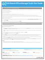
For example, to change the IP settings:
1. Press the right arrow button to display the
Network Settings option and the current IP
address.
2. Press the Enter button to go into editing mode.
3. Use the up and down arrow buttons to increment or
decrement the IP address indicated by the cursor.
4. Use the right and left arrow buttons to move to and change
the remaining digits of the IP address. Press the Enter button
to exit editing mode when finished.
5. Press the down arrow button to display the Subnet Mask
setting.
6. Edit the Subnet Mask in the same fashion as the IP address
and press the down arrow.
7. Edit the Gateway and DNS settings.
8. Press the down arrow after the DNS 3 setting to go to the
Save settings Yes/No prompt.
9. Select Yes at the prompt and press Enter to save changes.
Repeat steps 1-8 for the other options (console port and date/
time). Note: Another option, is to restore factory defaults. The
default password for this action is 999999. See the SLB User
Guide for more details.
After you save the values for your console manager, changes
take effect immediately.
4 CONFIGURING NETWORK (IP) SETTINGS
1. Install the unit in a 19-inch rack if desirable.
Warning: Be careful not to block the air vents on the sides of
the unit. If you mount it in an enclosed rack, we recommend
that the rack have a ventilation fan.
2. Connect the SLB directly to the network through the top
Ethernet port #1.
3. Connect up to eight serial console devices to the numbered
device ports on the front of the unit using the appropriate
cables and adapters.
4. To manage a device’s power, plug its power cord into one of
the eight power outlets.
5. If you are using the modem, connect it to the phone line.
6. Attach single-phase power cords to the primary AC input
connector and secondary AC input connector (optional) and
apply power.
7. Wait about a minute and a half for the boot process to end.
When the boot process ends, the status of each power outlet
displays on the LCD display. Detected faults or process
messages may also display.
2 INSTALLING THE SLB
2
SLB Branch Oce Manager Quick Start Guide

© 2016 Lantronix, Inc. Lantronix and SLB are trademarks of Lantronix, Inc., registered in the U.S. and other countries. Specifications subject to change without notice. All other trademarks and trade names are the
property of their respective holders. 900-670-R Rev G
Contact Technical Support
For technical support queries, visit http://www.lantronix.com/support or call North America (800) 422-7044 Monday – Friday from
6:00 a.m. – 5:00 p.m., Pacific Time, excluding holidays.
EMEA
Tel: +31 (0)20 77 14 424
Tel: +31 (0)76 52 36 740
China
Tel: +86.021.6237.8868
Asia/Pacific
Tel: +852 3428-2338
Japan
Tel: +81-3-6277-8802
Latest Firmware For the latest firmware downloads, visit http://www.lantronix.com/support/downloads
IP Address Assignment Tutorial To view a tutorial on how to assign an IP address, visit http://www.lantronix.com/support/tutorials
To log in to the SLB web page:
1. Open a web browser.
2. In the URL field, type https:// followed by the IP address of your SLB.
3. At the first login, enter sysadmin (all lower case) as the user and PASS (all upper case), the default factory password.
The first time you log in, the SLB Quick Setup page displays. Subsequent logins display the SLB Home Page. (To display Quick Setup
again, click the Quick Setup tab.)
4. Do one of the following:
• To bypass the Quick Setup page and go directly to configuring the SLB, click the Accept default Quick Setup settings checkbox
and click Apply.
• Update basic network parameters, if desired and click Apply.
To access the command line interface
1. Do one of the following:
• With a network connection, use a Telnet or SSH program to Telnet or SSH to xx.xx.xx.xx (the IP address in dot quad notation), and
press Enter. You should be at the login prompt.
Note: By default, Telnet is disabled. To enable Telnet,use the Services web page, a serial terminal connection, or an SSH connec-
tion.
• With a serial terminal connection, when the command line displays, press Enter.
2. Enter sysadmin as the user name and press Enter.
3. Enter PASS as the password and press Enter. The first time you log in, the Quick Setup script opens automatically. Subsequent
logins display the command prompt only. (To obtain the Quick Setup script again, use the admin quicksetup command.)
Note: Change the default password as soon as possible to prevent access by unauthorized personnel. Subsequent logins require
the username sysadmin and the appropriate password to log in as system administrator.
4. If the Quick Setup script displays, update basic network parameters, as desired. Otherwise, just press Enter until the command
prompt displays.By pressing Enter, you are accepting the current settings.
Notes:
• For general command line interface help, type help command line.
• For help with a specific command, type help followed by the command, for example,help set network or help admin firmware.
5 LOGGING INTO THE SLB WEB PAGE
6 LOGGING INTO THE COMMAND LINE INTERFACE
This section includes instructions for accessing both the web page and the command line interfaces. You can use either method to
configure all parameters.
3
SLB Branch Oce Manager Quick Start Guide

里面有
什么
SLB
快速入门指南
1 硬件评测
WHAT’S
INSIDE
SLB
Quick Start Guide
1 HARDWARE REVIEW
WHAT’S
INSIDE
SLB
Quick Start Guide
1 HARDWARE REVIEW
SLB Branch Of ce Manager Quick Start Guide
Power Cords
Included power cords vary for kit purchased. Please see www.lantronix.com for
additional inlet power cords available.
AC Voltage Kit Part Number Power Cord Description
(50/60 Hz)
100-120V SLB882KIT-15P SLPP12310-01 Inlet cord: IEC60320/C19
to NEMA 5-15P (15A)
100-120V SLB882KIT-20P SLPP12410-01 Inlet cord: IEC60320/C19
to NEMA 5-20P (20A)
200-240V SLB8824KIT-EU SLPP12810-01 Inlet cord: IEC60320/C19
to Schuko (EU)
SLPP12910-01 Inlet cord: IEC60320/C19
to BS1363 (UK)
200-240V SLB8824KIT-AP SLPP12A08-01 IEC60320/C19 to AS/NZS
3112 (AU/NZ)
SLPP12C08-01 IEC60320/C19 to CHINA/
GB (CN)
The SLB is a hybrid console manager and power manager in the form
of a space saving 19” 1RU design.
The SLB connects between a server or a piece of IT equipment and
an IP network or the Internet. Once installed on the IP network,
a remote user connects to the SLB using a secure web browser
(HTTPS/SSL), Secure Shell (SSH), or Telnet session. If a modem is
used in the SLB, dial-in access is possible in the event that the IP
network is unavailable. Once connected, the user has access to
the server or IT equipment’s command line interface (CLI) via the
console port to perform maintenance or management tasks. If the
equipment is connected to one of the SLB power outlets, then
(on/off/reboot) power control is possible.
The front LCD panel and keypad allows for quick and easy network
configuration. The front panel console port allows a dumb terminal
or PC with terminal emulation software to locally access manage-
ment functions and connected serial console devices. The device
ports allow simple connections to serial devices using adapters and
a standard Cat-5 cable. Connect one end of the Cat-5 cable to the
device port, and the other end to an adapter that attaches to the
serial console of the target system.
For example, to connect a PC to the device port of the SLB, you only
need the female DB9 adapter (Part #200.2070A) and a standard
Cat-5 cable, both of which are supplied with the SLB.
The default communication parameters for the device ports and the
console port are:
• 9600 baud • 8 data bits • No parity • 1 stop bit • No flow control
The power outlets allow your equipment to use the SLB as its power
source. Once connected you can remotely and securely control the
state of each outlet (on/off/reboot).
Accessories Included
Part Number Description
200.2066A Adapter: RJ45 to DB25M (DCE)
for Sun with DB25 female
200.2067A Adapter: RJ45 to DB25F (DCE)
for Sun with DB25 male and
some HP9000’s
200.2069A Adapter: RJ45 to DB9M (DCE) for
SGI Onyx
200.2070A Adapter: RJ45 to DB9F (DCE)
for HP9000, SGI Origin, IBM
RS6000,and PC-based Unix/
Linux servers
ADP010104-01 Adapter: RJ45 Rolled serial, 0.1m
(0.33 Ft.) for Cisco and Sun Netra
200.0063 Cable: RJ45 to RJ45, Cat-5, 2m
(6.6 Ft.)
500-153 Cable:RJ45 Loopback
Secondary AC Inlet
Modem
USB Port
Device ports 1-8
Console Port
10/100
Dual Ethernet
ports
Primary AC Inlet
KeypadLCD
Front View
110-120V AC 200-240V AC
Back View
Power outlets 1-8
Modem
USB Port
Secondary AC Inlet
Modem
USB Port
Device ports 1-8
Console Port
10/100
Dual Ethernet
ports
Primary AC Inlet
KeypadLCD
Front View
Back View
Power outlets 1-8
SLB Branch Of ce Manager Quick Start Guide
Power Cords Included
Included power cords vary for kit purchased. Please see www.lantronix.com for
additional inlet power cords available.
SLB Part #
Power Cord Part #
Power Cord Description Quantity
100-120 VAC (50/60 Hz)
SLB882KIT-15P SLPP12310-01 IEC60320/C19 to NEMA 5-15P (15A) 2
SLB882KIT-20P SLPP12410-01 IEC60320/C19 to NEMA 5-20P (20A) 2
200-240 VAC (50/60 Hz)
SLB8824KIT-EU SLPP12810-01 IEC60320/C19 to Schuko (EU) 2
SLPP12910-01 EC60320/C19 to BS1363 (UK) 2
SLB8824KIT-AP SLPP12A08-01 IEC60320/C19 to AS/NZS 3112 (AU/NZ) 2
SLPP12C08-01 IEC60320/C19 to CHINA/GB (CN) 2
SLB8824KIT-WW SLPP12810-01 IEC60320/C19 to Schuko (EU) 1
SLPP12910-01 EC60320/C19 to BS1363 (UK) 1
SLPP12A08-01 IEC60320/C19 to AS/NZS 3112 (AU/NZ) 1
SLPP12C08-01 IEC60320/C19 to CHINA/GB (CN) 1
The SLB is a hybrid console manager and power manager in the form
of a space saving 19” 1RU design.
The SLB connects between a server or a piece of IT equipment and
an IP network or the Internet. Once installed on the IP network,
a remote user connects to the SLB using a secure web browser
(HTTPS/SSL), Secure Shell (SSH), or Telnet session. If a modem is
used in the SLB, dial-in access is possible in the event that the IP
network is unavailable. Once connected, the user has access to
the server or IT equipment’s command line interface (CLI) via the
console port to perform maintenance or management tasks. If the
equipment is connected to one of the SLB power outlets, then
(on/off/reboot) power control is possible.
The front LCD panel and keypad allows for quick and easy network
configuration. The front panel console port allows a dumb terminal
or PC with terminal emulation software to locally access manage-
ment functions and connected serial console devices. The device
ports allow simple connections to serial devices using adapters and
a standard Cat-5 cable. Connect one end of the Cat-5 cable to the
device port, and the other end to an adapter that attaches to the
serial console of the target system.
For example, to connect a PC to the device port of the SLB, you only
need the female DB9 adapter (Part #200.2070A) and a standard
Cat-5 cable, both of which are supplied with the SLB.
The default communication parameters for the device ports and the
console port are:
•9600baud•8databits•Noparity•1stopbit•Noflowcontrol
The power outlets allow your equipment to use the SLB as its power
source. Once connected you can remotely and securely control the
state of each outlet (on/off/reboot).
Accessories Included
Part Number Description
200.2066A Adapter: RJ45 to DB25M (DCE)
for Sun with DB25 female
200.2067A Adapter: RJ45 to DB25F (DCE)
for Sun with DB25 male and
some HP9000’s
200.2069A Adapter: RJ45 to DB9M (DCE) for
SGI Onyx
200.2070A Adapter: RJ45 to DB9F (DCE)
for HP9000, SGI Origin, IBM
RS6000,and PC-based Unix/
Linux servers
ADP010104-01 Adapter: RJ45 Rolled serial, 0.1m
(0.33 Ft.) for Cisco and Sun Netra
200.0063 Cable: RJ45 to RJ45, Cat-5, 2m
(6.6 Ft.)
500-153 Cable:RJ45 Loopback
Secondary AC Inlet
Modem
USB Port
Device ports 1-8
Console Port
10/100
Dual Ethernet
ports
Primary AC Inlet
KeypadLCD
Front View
100-120V AC 200-240V AC
Back View
Power outlets 1-8
Modem
USB Port
Secondary AC Inlet
Modem
USB Port
Device ports 1-8
Console Port
10/100
Dual Ethernet
ports
Primary AC Inlet
KeypadLCD
Front View
Back View
Power outlets 1-8
SLB分支机构设备管理器快速入门指南
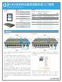
SLB是一种复合控制台管理器和电源管理器,采用节省空间的
19英寸1RU设计。
SLB将服务器或IT设备连接到IP网络或互联网上。一旦安装
在IP网络上,远程用户便可以通过安全网络浏览器(HTTPS/
SSL)、安全外壳 (SSH)或 Telnet会话连接到SLB。如 果 SLB中安
装了调制解调器,那么在IP网络不可用的情况下可以通过拨号
访问。一旦建立连接,用户通过控制台端口可以访问到服务器
或IT设备的命令行界面(CLI),进而完成维护或管理任务。如果
设备连接到SLB的一个电源输出插座上,那么就可以对其电源
进行控制(开/关/重启)。
利用前端LCD面板和数字小键盘可以方便快速地进行网络配
置。利用前面板上的控制台端口,可以通过一台哑终端或安装
有终端仿真软件的PC机实现本地访问管理功能,并对所连接
的串行控制台设备进行管理。这些设备端口允许使用适配器和
标准5类电缆与串行设备进行简单连接。将5类电缆的一端连
接到设备端口上,另一端连接到与目标系统串行控制台相连的
适配器上。
例如,要将一台PC连接到SLB的设备端口上,您只需要DB9母
头适配器(件号200.2070A)和一条标准5类电缆,两者均随
SLB一起提供。
设备端口和控制台端口的默认通信参数如下:
• 9600波特 • 8个数据位 • 无奇偶校验 • 1个停止位 • 无流量控制
电源输出插座允许您的设备将SLB作为其电源。一旦建立连
接,您便可以远程安全地控制每个插座的状态(开/关/重启)。
随附配件
件号 描述
200.2066A 适配器:RJ45转DB25M(DCE),
用于带DB25母头的Sun服务器
200.2067A 适配器:RJ45转DB25F(DCE),
用于带DB25公头的Sun服务器和
部分HP9000服务器
200.2069A 适配器:RJ45转DB9M(DCE),
用于SGI Onyx服务器
200.2070A 适配器:RJ45转DB9F(DCE),
用于HP9000、SGI Origin、IBM RS6000
服务器以及基于PC的Unix/Linux
服务器
ADP010104-01 适配器:RJ45超薄串口,0.1米( 0.33
尺 ),用 于 Cisco和Sun Netra服务器
200.0063 线缆:RJ45到RJ45 ,5类线,
2米( 6.6英 尺 )。
500-153 线缆:RJ45环回
前视图
100-120V AC 200-240V AC
LCD(液晶显示屏)
键盘
控制台端口
10/100
双以太网端口
后视图
副AC电源输入插座
主AC电源输入插座
设备端口1-8
电源输出插座1-8
USB端口
调制解调器
后视图
前视图
LCD(液晶显示屏)
键盘
控制台端口
副AC电源输入插座
10/100
双以太网端口
主AC电源输入插座
设备端口1-8
电源输出插座1-8
USB端口
调制解
调器
电源线随附
所附带的电源线因购买的产品套装不同而有所差别。请参阅
www.lantronix.com,了解可供使用的其他电源输入线。
SLB 件号 电源线件号 电源线描述 数量
100-120 VAC (50/60 Hz)
SLB882KIT-15P SLPP12310-01 IEC60320/C19 至 NEMA 5-15P (15A) 2
SLB882KIT-20P SLPP12410-01 IEC60320/C19 至 NEMA 5-20P (20A) 2
200-240 VAC (50/60 Hz)
SLB8824KIT-EU SLPP12810-01 IEC60320/C19 至 Schuko (EU) 2
SLPP12910-01 IEC60320/C19 至 BS1363 (UK) 2
SLB8824KIT-AP SLPP12A08-01 IEC60320/C19 至 AS/NZS 3112 (AU/NZ) 2
SLPP12C08-01 IEC60320/C19 至 CHINA/GB (CN) 2
SLB8824KIT-WW SLPP12810-01 IEC60320/C19 至 Schuko (EU) 1
SLPP12910-01 IEC60320/C19 至 BS1363 (UK) 1
SLPP12A08-01 IEC60320/C19 至 AS/NZS 3112 (AU/NZ) 1
SLPP12C08-01 IEC60320/C19 至 CHINA/GB (CN) 1
4
电源分配器(带适配器功能)

1.如果需要的话,可以将设备安装在一个19英寸机架上。
警告:小心不要堵住设备两侧的散热孔。如果设备安装在一个
封闭的机架上,建议机架配备一个排风扇。
2. 将SLB通过上方的以太网端口#1直接连接到网络上。
3. 使用合适的电缆和适配器,最多可以将八台串行控制台设备连接
到本设备前面板上带编号的设备端口。
4.要管理一台设备的电源,请将其电源线插入到八个电源输出插
座中的任一个。
5.如果您使用调制解调器,请将其连接到电话线。
6. 将电单相源线连接到主AC电源输入接口和副AC电源输入接口
(可选),并接通电源。
7. 等待约一分半钟左右,直到启动过程结束。当启动过程结束时,每
个电源输出插座的状态将显示在LCD显示屏上。还可能显示检测
到的故障或过程消息。
2 安装SLB
SLB分支机构设备管理器快速入门指南
设置基本网络参数的最快捷方法是用前面板上的数字小键盘和显
示器。
注:如果您愿意的话,您可以通过使用Telnet或SSH从命令行界面
上的“快速设置”脚本上手,或者通过直接将一台终端连接到控制台
(RS -232)端口上开始工作。该网页界面还提供了一个“快速设置”
页面。
请参见用户指南中“快速设置”中的使用说明。
• 使用向右箭头和向左箭头按钮从一个选项跳到另一个选项。
• 使用向上箭头和向下箭头按钮在某个选项所对应的各个参数间
进行选择,或者用来增加或减少参数值。
• 使用中间的“确定”按钮进入或退出编辑模式并保存更改。
注:如果30秒内没有按下任何按钮,那么前面板将显示超时信息,
放弃未保存的更改,并返回到显示主机名和时钟的画面。
例如,要更改IP设置:
1.按向右箭头按钮显示“网络设置”选项和当
前IP地址。
2. 按“确定”按钮进入编辑模式。
3. 使用向上箭头和向下箭头按钮来增加或减少由光标指示的IP
地址。
4.使用向右箭头和向左箭头按钮移至IP地址的其他数位,然后进
行更改。设置完成后,按“确定”按钮退出编辑模式。
5.按向下箭头按钮显示“子网掩码”设置。
6.按照与IP地址相同的方式编辑“子网掩码”,然后按向下箭头
按钮。
7. 编辑“网关”和“域名服务器”设置。
8.在“域名服务器3”设置之后按向下箭头按钮,跳转到“保存设
置是/否”提示。
9.在该提示符下选择“是”,并 按“确定”按钮保存更改。
对其他选项(控制台端口和日期/时间)重复步骤1-8 。
注意:还有一种选择就是恢复出厂默认值。该操作的默认密码
为999999。更多详情请参见SLB用户指南。
保存控制台管理器设置后,更改立即生效。
4 配置网络(IP)设 置
3
IP寻址
SLB的两个网络端口(Eth1和Eth2)默认为由DHCP分配的IP地址。如果您要指定一个不同的IP地址,那么该地址必须在有效范围内,并且
在您的网络上是唯一的,使用与您的工作站相同的子网掩码。
要配置SLB,您需要以下信息:
IP地址(若尚未分配):_______ . _______ . _______ . _______
子网掩码(若尚未分配):_______ . _______ . _______ . _______
网关:_______ . _______ . _______ . _______
域名服务器:_______ . _______ . _______ . _______
5
电源分配器(带适配器功能)

版权所有 © 2016 Lantronix公司。Lantronix和SLB为Lantronix公司在美国和其他国家的注册商标。规格如有变动,恕不另行通知。所有其他商标和商业名称属于各自拥有者所有。
900-670-R 修订版G
联系技术支持
如需技术支持咨询,请访问http://www.lantronix.com/support,或致电北美(800)422-7044(太平洋时间周一至周五上午6:00-下午5:00,
节假日除外)。
欧洲、中东、非洲地区
电话:+31 (0)20 77 14 424
电话:+31 (0)76 52 36 740
中国
电话:+86.021.6237.8868
亚洲/太平洋地区
电话:+852 3428-2338
日本
电话:+81-3-6277-8802
最新固件要下载最新固件,请访问http://www.lantronix.com/support/downloads
IP地址分配教程要查看有关如何分配IP地址的教程,请访问http://www.lantronix.com/support/tutorials
SLB分支机构设备管理器快速入门指南
要登录到SLB网页:
1. 打开网络浏览器。
2. 在URL字段中输入https://,后面加上您的SLB的IP地址。
3. 第一次登录时,输入sysadmin(全部小写)作为用户名,默认的出厂密码为PASS(全部大写)。
当您第一次登录时,将显示SLB“快速设置”页面。以后登录时将显示SLB主页。(若要再次显示“快速设置”,请单击“快速设置”选项卡。)
4. 执行下列操作之一:
• 要绕过“快速设置“页面直接配置SLB,请点击“接受默认快速设置”复选框,并点击“应用”。
• 如果需要的话,更新基本网络参数,然后点击“应用”。
要访问命令行界面
1. 执行下列操作之一:
• 在使用网络连接的情况下,利用Telnet或SSH程序连接到 xx.xx.xx.xx (IP地址点分表示法),然后按“确定”按钮。此时应显示登录提示
符。
注意:Telnet默认为禁用。要启用Telnet远程登录,需要使用“服务”网页、一个串行终端连接或SSH连接
• 在使用串行终端连接的情况下,当显示命令行时,请按“确定”。
2. 输入sysadmin作为用户名,然后按“确定”。
3. 输入PASS作为密码,然后按“确定”。当您第一次登录时,会自动打开“快速设置”脚本。以后登录时将只显示命令提示符。(若要再次获
得“快速设置”脚本,请使用admin quicksetup命 令 。)
注意:请尽快修改默认密码,以防止未经授权人员访问。以后登录时,需要输入用户名sysadmin和相应的密码,以系统管理员身份登录。
4. 如果显示“快速设置”脚本,请根据需要更新基本网络参数。否则,只需按住确定,直到显示出命令提示符。按确定,表明您接受当前的设
置。
注意:
• 如需一般的命令行界面帮助,请在命令行输入help。
• 如需某个特定命令的帮助,请输入help,后面跟该命令,例如,help set network或 help admin firmware。
5 登录到SLB网页
6 登录到命令行界面
本节包含网页访问和命令行两种界面的使用说明。您可以使用任一方法配置全部的参数。
6
电源分配器(带适配器功能)
-
 1
1
-
 2
2
-
 3
3
-
 4
4
-
 5
5
-
 6
6


Lantronix Lantronix SLB: Branch Office Manager クイックスタートガイド
- タイプ
- クイックスタートガイド
その他のドキュメント
-
 Crem Coffee Onyx 取扱説明書
-
Posiflex AURA PP-8802 ユーザーマニュアル
-
HP Latex 210 Printer (HP Designjet L26100 Printer) ユーザーマニュアル
-
ATEN PE1216A クイックスタートガイド
-
Dell QLogic Family of Adapters ユーザーガイド
-
-
-
-
-
