TSX-100
12
2
2
6
4
6
2
1
5
5
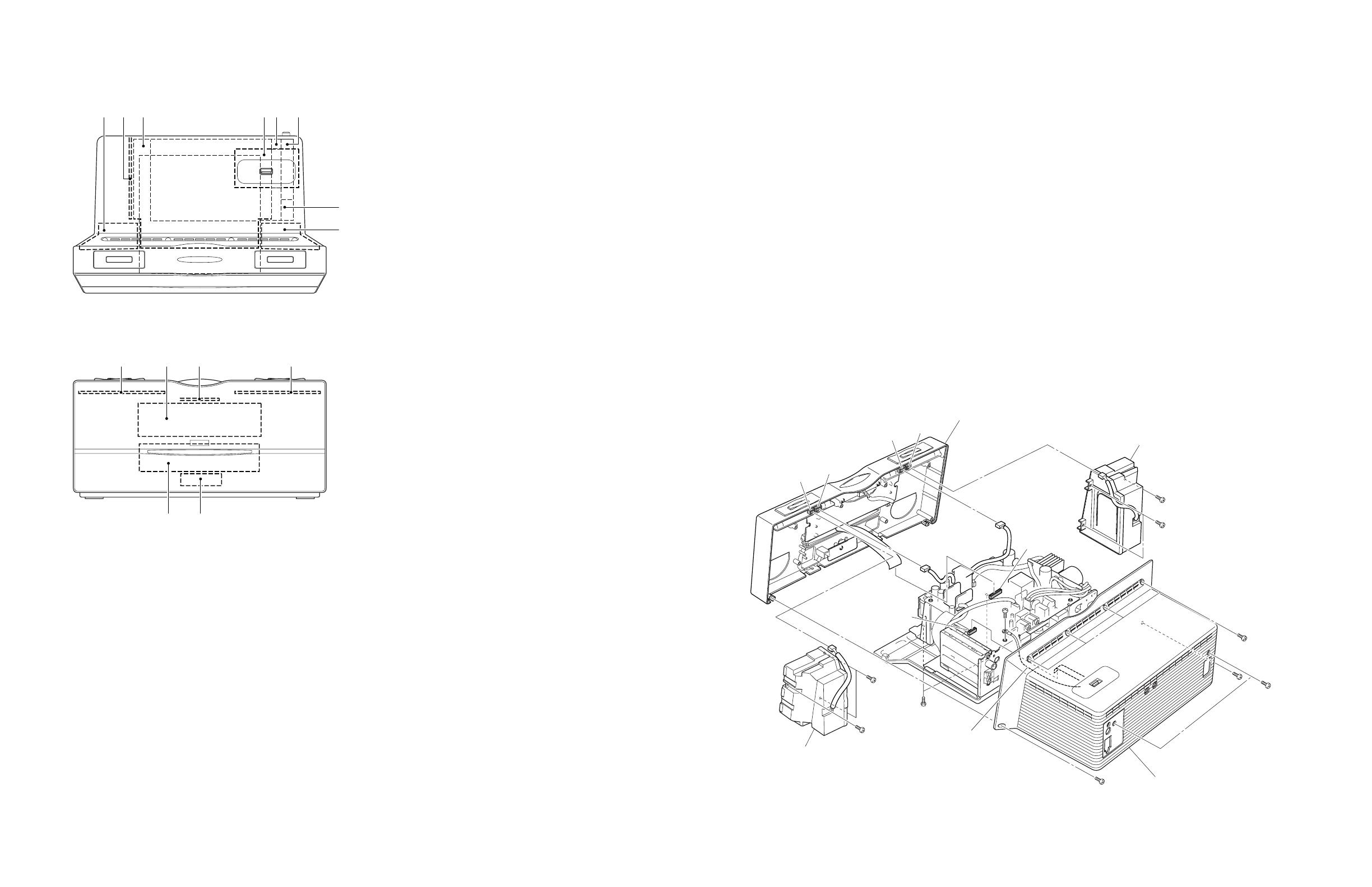
Front panel unit
CN83
CN18
CN17
CN82
Speaker L ass'y
CN84
CN85
Speaker R ass'y
Rear cabinet ass'y
3
Ground lead
■ INTERNAL VIEW
321 4 5
1
2
3
4
5
6
7
8
9
0
A
B
C
D
SPEAKER L ASS'Y
SMPS P.C.B.
MAIN (1) P.C.B.
MAIN (4) P.C.B. (U, A, J models)
MAIN (6) P.C.B. (R, B, G models)
DAB MODULE (B model)
MAIN (7) P.C.B. (B model)
AM/FM TUNER MODULE
MAIN (2) P.C.B.
SPEAKER R ASS'Y
MAIN (8) P.C.B.
MAIN (3) P.C.B.
MAIN (5) P.C.B.
MAIN (9) P.C.B.
MAIN (10) P.C.B.
CD MECHANISM UNIT
7
8
09BA
DC
6
Fig. 1
1. Removal of Rear Cabinet Ass’y
a. Remove 2 screws (1) and 6 screws (2). (Fig. 1)
b. Pull out the rear cabinet rearward slowly. (Fig. 1)
c. Remove CN17. (Fig. 1)
d. Remove screw (3) and then remove the ground lead.
(Fig. 1)
e. Remove the rear cabinet ass’y. (Fig. 1)
2. Removal of Front Panel Unit
a. Remove 2 screws (4). (Fig. 1)
b. Remove CN18, CN82 and CN84. (Fig. 1)
c. Remove the front panel unit forward. (Fig. 1)
3. Removal of Speaker L Ass’y and Speaker R Ass’y
a. Remove 3 screws (5). (Fig. 1)
b. Remove CN83. (Fig. 1)
c. Remove the speaker L ass’y. (Fig. 1)
d. Remove 3 screws (6). (Fig. 1)
e. Remove CN85. (Fig. 1)
f. Remove the speaker R ass’y. (Fig. 1)
1 2
3
4
5
6
Top view
Front view
■ DISASSEMBLY PROCEDURES /
(Remove parts in the order as numbered.)
Disconnect the power cable from the AC outlet.
Safety Measures
• Some internal parts in this product contain high volt-
ages and are dangerous. Be sure to take safety mea-
sures during servicing, such as wearing insulating
gloves.
• C971 on the SMPS (2) P.C.B. is dangerous even after
the power is turned off because an electric charge re-
mains and a high voltage continues to exist there.
Before starting any repair work, perform discharge by
connecting a discharge resistor (5k-ohms/10 W) be-
tween terminals of the capacitor. The time required for
discharging is about 30 seconds.
After the repair work, also perform discharge in the
same manner.


