
– 1 –
Quick Start Guide
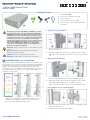
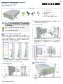
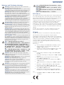
Install Rack-Rails in a 19-inch Rack
The chassis requires L-shaped rack-rails (ordered separately) to first
be installed in an 19-inch rack. Use the rack alignment templates to
install rack-rails at the correct locations in the rack allowing for the
height of the chassis (4RU). Three templates per rack post are
required for the full rack height. It is recommended to use a total of
12 templates, three on each rack post. Note that the magnetic
templates can be reused.
1. Align the cable-management T-pin on the rails with the Minipack
numbers on the templates. The Minipack numbers are color
coded for each template position on a rack post; green
(bottom), orange (middle), and blue (top).
a. Using Screw-Type Rack-Rails
1. Use two #12-24-16L rack screws to secure each rack-rail to the
front post of the rack.
2. Adjust the length of the rack-rails to reach the rear post of the
rack and secure them with two #12-24-16L rack screws on each
side.
b. Using Tool-Less Rack-Rails
1. Push the latch button to lock each rack-rail to the front post of
the rack. (Optionally use rack screws for added security.)
2. Adjust the length of the rack-rails to reach the rear post of the
rack and push the latch button to lock them to the post.
(Optionally use #12-24-16L rack screws for added security.)
c. Using Adapters for 29-inch-Deep Racks
1. Use two #12-24-16L rack screws to secure each adapter to the
rear post of the rack.
2. Attach the rack rails to the rack adapters.
Warning:
For a safe and reliable installation, use only
the accessories and screws provided with the Minipack-
AS8000. Use of other accessories and screws could result
in damage to the unit. Any damages incurred by using
unapproved accessories are not covered by the warranty.
Avertissement:
Pour une installation sûre et fiable,
utilisez uniquement les accessoires et les vis fournies avec
le Minipack-AS8000. L’utilisation d’autres accessoires et
vis pourrait endommager l’appareil. Les dommages
causés par l’utilisation d’accessoires non approuvés ne
sont pas couverts par la garantie.
Warning:
The top of the enclosure is a hot surface. Do not
touch!
Avertissement:
La surface du dessus du boîtier est
brûlante. Ne pas la toucher!
Caution:
Install in a restricted access location.
Attention:
Installer dans un endroit d’accès restreint.
1
1
Bottom Middle Top
1
2
Front Post Rear Post
1
2
Front Post Rear Post
1
2
E082019-CS-R02
150200002142A
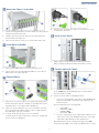
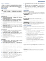
128-Port 100G Chassis Switch
Minipack-AS8000
1.
Minipack-AS8000
2. AC power cord retention clip (x4)
3. Power cord (x4)
4. Console Cable—RJ-45 to DB-9
5. Documentation—Quick Start Guide (this
document)
Package Contents
5
1
2 3
www.edge-core.com
4

Quick Start Guide
– 2 –
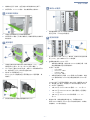
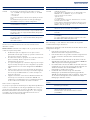
Mount the Chassis in the Rack
1. Use the four lifting handles to place the chassis onto the installed
L-shaped rack-rails in the rack.
2. Slide the chassis fully into the rack until its front brackets are
flush with the front rack posts.
3. Use four #12-24-16L screws to secure the switch in the rack.
Install Rack Air Baffles
1. Install rack air baffles between chassis units in the rack.
2. Use two M4 screws (included with the baffle) to secure the air
baffle to the front of the rack-rails.
Connect Power
1. Install up to four universal AC power supply units (PSUs) in the
chassis. (The whole chassis is capable of operating with only two
installed PSUs; 3 or 4 PSUs provide redundancy.)
2. PSUs can only be installed in one correct orientation. If a PSU
does not install flush with the chassis, remove it and reinstall in
the 180-degree opposite orientation.
3. Connect an external AC power source to the PSUs.
Connect the AC sockets on the PSUs to at least two separate AC
power circuits for redundancy.
4. Use the power cord retention clips to secure the power cord
connections to the PSUs.
Verify System Power
1. Verify system power by checking the LEDs on the chassis.
When operating normally, the LEDs should all be on blue.
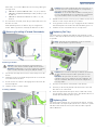
Connect Network Cables
1. Connect a 100-ohm Category 5e (or better) twisted-pair cable
to the 1000BASE-T RJ-45 Management port on the System
Controller Module (SCM).
2. Connect network cables to QSFP28 interfaces:
■
If you are connecting fiber optic cables, install QSFP28 fiber
transceivers and then connect fiber optic cabling to the
transceiver ports.
The following transceivers are supported:
◆
CLR4 100G
◆
LR4/LR4-lite 100G
◆
CWDM4 100G
◆
OpenOptic 100G
■
If you are using twinax copper cables (DAC cables) for port
connections, connect the QSFP28 transceivers on the end
of the DAC cables directly into the QSFP28 slots.
The QSFP28 ports can be configured as single-lane 100G
mode, dual-lane 50G mode, single-lane 40G mode, four-lane
2
1
1
3
1
2
4
2
3
1
3
5
1
6
1
2

Quick Start Guide
– 3 –
25G mode, or four-lane 10G mode. The following cable types
are supported:
■
100 GbE to QSFP28 100 GbE cable: 1 m, 2 m, and 3 m
■
100 GbE to 2xQSFP28 50 GbE split cable (Y-cable): 1 m, 2
m, and 3 m
■
100 GbE to 4xSFP28 25 GbE fanout cable: 1 m, 2 m,
and 3 m
3. As connections are made, check the port status LEDs to be sure
the links are valid.
Each QSFP28 port has one LED for all port configuration
modes. When a port has a valid link, the LED turns on blue.
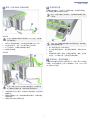
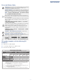
Removing/Installing SCM and PIM Modules
Removing a Module
1. Use an ESD wrist strap and connect it to the ESD point on the
chassis.
2. Grasp the release lever handle and pull it down to release the
lever latch from the module.
3. Pull the release lever down to disengage the module from the
chassis backplane.
4. Slide the module out of the chassis.
Installing a Module
1. With the module release lever fully open, slide the module into a
chassis slot until it stops and can go no further.
2. Slowly push the release lever up to engage the module with the
chassis backplane. The module should immediately power on.
3. Latch the release lever handle into its closed position.
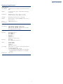
Replacing Fan Trays
The switch system is shipped with eight fan trays installed. If a fan
failure is detected, the defective fan tray should be replaced as soon
as possible.
1. Press the release button on the handle of the fan tray.
2. Pull firmly on the fan tray handle until the fan tray is free and
then slide it out of the switch.
3. Insert the replacement fan tray into the slot and slide it slowly
into the chassis until it clicks into place. The LED should turn on
and the fans immediately start to operate.
Replacing PSUs
The switch system supports up to four PSUs in the chassis. If a PSU
fails and needs to be replaced, the system will to continue to operate
with three PSUs installed. However, the PSU should be replaced
within 10 minutes.
Caution:
Disconnect all network connections before
removing a Port Interface Module (PIM) from the chassis.
Attention:
Débrancher tous les raccords réseau avant de
retirer le module d’interface des ports (MIP) du châssis.
7
3
4
1
2
1
2
3
Caution:
If an SCM or PIM module does not power on or
its release lever not correctly latch into its closed position,
remove the module and install again.
Attention:
Si un module SCM ou MIP ne s’allume pas ou
si le levier de dégagement ne s’enclenche pas correctement
en position fermée, retirer le module et le réinstaller.
Note:
Fan trays are hot-swappable, you do not need to
power off the switch to replace a fan tray.
Caution:
Do not leave a fan tray slot without an installed
fan tray. Failed fan trays should be replaced as soon as
possible.
Attention:
Ne pas laisser la cavité où loge le tiroir du
ventilateur sans y avoir installé un tiroir de ventilateur. Les
tiroirs de ventilateur défectueux doivent être remplacés le
plus tôt possible.
8
2
1
9

Quick Start Guide
– 4 –
Hardware Specifications
Switch Chassis
Size (WxDxH) 440.4 x 755.5 x 176.2 mm (17.34 x 29.74 x 6.94 in.),
4RU
Weight 55 kg (121.25 lb), with 1 SCM, 8 PIMs, 8 fan trays,
and 4 PSUs
Temperature Operating: 0° C to 45° C (32° F to 113° F)
Storage: -40° C to 70° C (-40° F to 158° F)
Humidity Operating: 5% to 85% (non-condensing)
Altitude Operating: Up to 1829 m (6000 ft) at 0° C to 35° C
(32° F to 95° F)
Power
Consumption
3000 Watts maximum
System
Power Rating 100–120 VAC, 50/60Hz, 10A per PSx4
200–240 VAC, 50/60Hz, 7A per PS x4
200–277 VAC, 50/60Hz, 9A per PS x4 (except Bel
Fuse and Murata power supply)
Regulatory Compliances
Emissions EN 55032 Class A
EN 61000-3-2
EN 61000-3-3
FCC Class A
CE Mark
VCCI Class A
BSMI Class A, CNS 13438
Immunity EN 55024
IEC 61000-4-2/3/4/5/6/8/11
Safety UL/EN 60950-1
UL/EN 62368-1
CB Report
BSMI, CNS 14336-1
Laser Safety Fiber needs to use a Class 1 Laser Product and meet
the following standards:
◆
IEC/EN 60825-1 (3rd. edition)
◆
U.S. Code of Federal Regulations 21 CFR 1040
◆
Canadian Radiation Emitting Devices Act, REDR
C1370
Taiwan RoHS CNS 15663

– 1 –
快速入門指南
在 19 英吋機架中安裝機架滑軌
機箱的要求為:首先將 L 形機架滑軌安裝在 19 英吋機架中 (另
外購買)。使用機架對齊模板,將機架滑軌安裝在機架中的正確
位置,並具足夠機箱高度 (4RU)。整個機架高度要求每個機架
柱具備三個模板。建議總共使用 12 個模板,每個機架柱上有三
個模板。請注意,磁性模板可重複使用。
1.
將滑軌上整理電線的
T-pin
與模板上的
Minipack
編號對齊。
Minipack
編號按顏色區分,針對機架柱上的每個模板位置;綠
色 (底部)、橙色 (中間)、藍色 (頂端)。
a. 使用螺絲型機架滑軌
1.
使用兩個#
12-24-16L
機架螺絲,將每個機架滑軌固定於機架
前柱。
2. 調整機架滑軌的長度以觸及機架的後柱,並用兩個# 12-24-
16L 機架螺絲在兩邊固定它們。
b. 使用免工具機架滑軌
1.
按下閂鎖按鈕,將每個機架滑軌鎖定到機架前柱。(可選擇使
用機架螺絲以增加安全性。)
2. 調整機架滑軌的長度以觸及機架的後柱,並按下閂鎖按鈕將
其鎖定到機架柱。(可選擇使用# 12-24-16L 機架螺絲,以
增強安全性。)
c.29 英吋深機架應使用變壓器
1.
使用兩個#
12-24-16L
機架螺絲,將每個變壓器固定於機架的
後柱。
2. 將機架滑軌連接至機架變壓器。
將機箱安裝在機架中
1.
使用四個吊裝把手,將機箱放置在已安裝於機架中的
L
形機架
滑軌上。
警告:
為了可以更安全的使用與安裝機台,請務必使用
Minipack-AS80000 隨貨附贈的配件,避免導致設備損壞
或其他風險產生。 使用未經批准的配件造成的任何損壞,
均不在保修範圍內。
警告:
外殼頂端表面為高溫狀態。請勿觸摸!
注意:
安裝在管制進出的位置。
1
底部 中間 頂端
1
前柱 後柱
1
2
前柱 後柱
1
2
2
1
2
1
1
1.
Minipack-AS8000
2. 交流電源線固定夾 (x4)
3. 電源線 (x4)
4. 控制電纜- RJ45 轉 DB-9
5. 文件-
快速入門指南
(本文件)
包裝內容物
1
128 埠 100G 機殼交換器
Minipack-AS8000
5
2 3
www.edge-core.com
4

快速入門指南
– 2 –
2. 將機箱完全滑入機架,直至其前支架與前機架支柱齊平。
3. 使用四個# 12-24-16L 螺絲,將交換器固定在機架中。
安裝機架導風板
1.
在機架中的機箱單位之間安裝機架導風板。
2. 使用兩個 M4 螺絲 (附帶於導風板)將導風板固定於機架滑
軌的前端。
連接電源
1.
在機箱中最多安裝四個通用交流電源供應器 (
PSU
)。(機箱
僅需兩個
PSU
運作;第
3
或
4
的
PSU
則用於備援。)
2. PSU 只能以正確的方向進行安裝。如果 PSU 未與機箱齊平安
裝,請將其卸下並以 180 度反向重新安裝。
3. 將外部 AC 電源連接至 PSU。
將 PSU 上的 AC 插座連接至少兩個獨立的 AC 電源電路,做
為備用。
4. 使用電源線固定夾將電源線連接固定到 PSU。
確認系統電源
1.
透過檢查機箱上的
LED
來驗證系統電源。
運作正常時,LED 應全部亮藍燈。
連接網路線
1.
將
100
歐姆
5e
等級 (或以上)雙絞線,連接到系統控制器模
組(
SCM
)上的
1000BASE-T RJ-45
管理埠。
2. 將網路線連接到 QSFP28 介面:
■
若要連接光纖電纜,請先安裝 QSFP28 光纖收發器,然後
將光纖纜線連接至收發器連接埠。
支援以下收發器:
◆
CLR4 100G
◆
LR4/LR4-lite 100G
◆
CWDM4 100G
◆
OpenOptic 100G
■
如果使用雙芯銅心電纜 (DAC 電纜)進行埠連接,請將
DAC 電纜末端的 QSFP28 收發器直接連接到 QSFP28 插
槽。
QSFP28 端口可以配置為單通道 100G 模式、雙通道 50G 模
式、單通道 40G 模式、四通道 25G 模式或四通道 10G 模
式。支援以下電纜類型:
■
100 GbE 到 QSFP28 100 GbE 電纜:1 m、2 m 和 3 m
■
100 GbE 至 2xQSFP28 50 GbE 分離式電纜(Y 型電纜):
1 m、2 m 和 3 m
■
100 GbE 至 4xSFP28 25 GbE 扇出電纜:1 m、2 m
和 3 m
3. 連接完成後,請檢查連接埠狀態 LED,確保連結有效。
每個 QSFP28 埠都有一個 LED 用於所有埠組態模式。當埠有
效連接時,LED 將亮起藍色。
3
1
2
4
2
3
1
3
5
1
6
2
1

快速入門指南
– 3 –
移除 / 安裝 SCM 和 PIM 模組
移除模組
1.
使用
ESD
靜電消除腕帶,並將其連接到機箱上的
ESD
點。
2. 抓住釋放桿把手,並向下拉以釋放模組上的桿鎖。
3. 向下拉釋放桿,使模組從機箱背板鬆開。
4. 將模組滑出機箱。
安裝模組
1.
在模組釋放桿完全打開時,將模組滑入機箱插槽,直至其無法
繼續前進。
2. 將釋放桿緩慢向上推,使模組與機箱背板嚙合。該模組應立
即開啟電源。
3. 將釋放桿把手鎖定在關閉位置。
更換風扇托盤
交換器系統出廠時,已安裝了八個風扇托盤。若檢測到風扇故
障,應盡速更換有問題的風扇托盤。
1.
按下風扇托盤把手上的釋放按鈕。
2. 用力拉動風扇托盤把手,直至風扇托盤鬆開,再將其滑出交
換器。
3. 將替換風扇托盤插入插槽,然後將其緩慢滑入機箱,直至其
就定位。LED 應該打開,且風扇立即開始運轉。
更換 PSU (電源供應器)
交換器系統在機箱中最多可支援四個 PSU。如果一個 PSU 故障並
須更換,系統可靠著其它三個 PSU 繼續運作。然而,該 PSU 須在
10 分鐘內完成更換。
注意:
從機箱中移除埠介面模組 (PIM)之前,請中斷
所有網路連接。
注意:
如果 SCM 或 PIM 模組未接通電源,或其釋放桿
未正確鎖定至關閉位置,請移除模組並重新安裝。
7
3
2
4
1
3
2
1
說明:
風扇托盤是可熱插拔的,無需關閉交換器即可進
行更換。
注意:
每一風扇托盤插槽都須安裝風扇托盤。風扇托盤
故障時應盡速更換。
8
1
2
9

快速入門指南
– 4 –
硬體規格
交換器機箱
尺寸(寬 x 深
x 高)
440.4 x 755.5 x 176.2 mm
(17.34 x 29.74 x 6.94 吋 ),4RU
重量 55 公斤 (121.25 磅),附 1 個 SCM,8 個 PIM,8
個風扇托盤和 4 個 PSU
溫度 操作:0° C 至 45° C (32° F 至 113° F)
儲存:-40° C 至 70° C (-40° F 至 158° F)
濕度 操作:5%至 85%(非冷凝)
海拔 操作:在 0°C 至 35°C (32°F 至 95°F)的溫度下,
最高可達 1829 公尺 (6000 英呎)
耗電量 最大 3000 瓦
系統
額定功率 每 PSx4: 100-120 VAC,50 / 60Hz,10 A
每 PSx4: 200–240 VAC,50/60Hz,7A
每 PSx4: 200–277 VAC,50/60Hz,9A (Bel Fuse
和 Murata 電源除外)
符合法規
排放
EN 55032 Class A
EN 61000-3-2
EN 61000-3-3
FCC Class A
CE Mark
VCCI Class A
BSMI Class A, CNS 13438
電磁耐受性
EN 55024
IEC 61000-4-2/3/4/5/6/8/11
安全性
UL/EN 60950-1
UL/EN 62368-1
CB Report
BSMI, CNS 14336-1
雷射安全
Fiber needs to use a Class 1 Laser Product and meet
the following standards:
◆
IEC/EN 60825-1 (3rd. edition)
◆
U.S. Code of Federal Regulations 21 CFR 1040
◆
Canadian Radiation Emitting Devices Act, REDR
C1370
臺灣限用有害
物質指令
(RoHS)
CNS 15663

Quick Start Guide
– 1 –
Warnings and Cautionary Messages
FCC Class A
This equipment has been tested and found to comply with the limits
for a Class A digital device, pursuant to part 15 of the FCC Rules.
These limits are designed to provide reasonable protection against
harmful interference when the equipment is operated in a
commercial environment. This equipment generates, uses, and can
radiate radio frequency energy and, if not installed and used in
accordance with the instruction manual, may cause harmful
interference to radio communications. Operation of this equipment
in a residential area is likely to cause harmful interference in which
case the user will be required to correct the interference at his own
expense.
For fiber optic connections, you may use 50/125 or 62.5/125
micron multimode fiber or 9/125 micron single-mode fiber.
CE Mark
CE Mark Declaration of Conformance for EMI, Safety, and RoHS.
This information technology equipment complies with the
requirements of the RoHS Directive 2011/65/EU, Council Directive
2014/30/EU on the Approximation of the laws of the Member States
relating to Electromagnetic Compatibility, and 2014/35/EU for
electrical equipment used within certain voltage limits. For the
evaluation of the compliance with these Directives, the following
standards were applied:
RFI Emission:
■
Limit according to EN 55032:2015+AC:2016, Class A
■
Limit for harmonic current emission according to EN
61000-3-2:2014, Class A
■
Limitation of voltage fluctuation and flicker in low-voltage
supply systems according to EN 61000-3-3:2013
Immunity:
■
Product family standard according to EN 55024:2010+
A1:2015
■
Electrostatic Discharge according to IEC 61000-4-2:2008
ED. 2.0
■
Radio-frequency electromagnetic field according to
IEC 61000-4-3:2010 ED. 3.2
■
Electrical fast transient/burst according to IEC 61000-4-
4:2012 ED. 3.0
■
Surge immunity test according to IEC 61000-4-5:2017 ED.
3.1
■
Immunity to conducted disturbances, Induced by radio-
frequency fields: IEC 61000-4-6:2013 ED. 4.0
■
Power frequency magnetic field immunity test according to
IEC 61000-4-8:2009 ED. 2.0
■
Voltage dips, short interruptions and voltage variations
immunity test according to IEC 61000-4-11:2017 ED. 2.1
LVD:
■
EN 60950-1:2006+A11:2009+A1:2010+A12:2011
+A2:2013
Warning:
Installation and removal of the unit must be
performed by qualified personnel only.
Warning:
When connecting this device to a power outlet,
connect the field ground lead on the tri-pole power plug to
a valid earth ground line to prevent electrical hazards.
Warning:
This switch uses lasers to transmit signals over
fiber optic cable. The lasers are compliant with the
requirements of a Class 1 Laser Product and are inherently
eye safe in normal operation. However, you should never
look directly at a transmit port when it is powered on.
Warning:
When selecting a fiber QSFP28 device,
considering safety, please make sure that it can function at
a temperature that is not less than the recommended
maximum operational temperature of the product. You must
also use an approved Laser Class 1 QSFP28 transceiver.
Avertissement:
L’installation et la dépose de l’unité ne
doivent être réalisées que par du personnel qualifié.
Avertissement:
Lorsque vous branchez cet appareil sur
une prise électrique, la terre de la fiche à trois pôles doit être
branchée sur une ligne mise à la terre pour écarter tout
danger électrique.
Avertissement:
Ce commutateur utilise des lasers pour
transmettre des signaux via un câble de fibre optique. Ces
lasers répondent aux exigences des produits laser de classe
1 et sont sans danger intrinsèque pour les yeux, sous réserve
de leur utilisation normale. Vous ne devrez cependant
jamais regarder directement un port de transmission lorsque
ce dernier est sous tension.
Mise en garde :
Lorsque vous utilisez un dispositif fibre de
type QSFP28, en ce qui concerne la sécurité, assurez-vous
qu’il puisse fonctionner à une température inférieure à la
température maximale de fonctionnement recommandée du
produit. Utilisez également un émetteur-récepteur laser
QSFP28 de classe 1 agrée.
警告:
設備安裝和移除須由合格人員進行。
警告:
將此設備連接到電源插座時,請將三極插頭上的
接地導線連接到有效的接地線,以免發生電氣危險。
警告:
該交換器使用雷射透過光纖傳輸信號。雷射符合
第 1 類雷射產品的要求,基本上於正常操作時,不會對
眼睛造成傷害。然而,在電源開啟時,切勿直視傳輸
埠。
警告:
選擇光纖 QSFP28 設備時,請考慮安全性,並確
認其在產品建議的最高工作溫度時,仍能運作。您還必
須使用經認可的第 1 類雷射 QSFP28 收發器。
Caution:
Wear an anti-static wrist strap or take other
suitable measures to prevent electrostatic discharge when
handling this equipment.
Caution:
Do not plug a phone jack connector in the RJ-45
port. This may damage this device.
Caution:
Use only twisted-pair cables with RJ-45
connectors that conform to FCC standards.
Caution:
For pluggable equipment, the socket outlet shall
be installed near the equipment and shall be easily
accessible.
Attention:
La manipulation de cet équipement requiert le
port d’un bracelet antistatique ou l’utilisation d’autres
mesures pour éviter toute décharge électrostatique.
Attention:
Ne branchez pas un connecteur téléphonique
dans le port RJ-45. Vous risqueriez d’endommager
l’appareil.
Attention:
Ne branchez que des fils torsadés par paires
conformes aux normes FCC sur les connecteurs RJ-45.
Attention:
Dans le cas d’un appareil à brancher, la prise
d’alimentation doit être installée à proximité de
l’équipement et doit rester facilement accessible.
注意:
請配戴防靜電腕帶或採取其他適當措施,避免處
理設備時的靜電放電。
注意:
請勿將電話插孔接頭插入 RJ-45 連接埠。這可能
損壞此裝置。
注意:
僅限使用具備 RJ-45 接頭且符合 FCC 標準的雙
絞線電纜。
注意:
可插拔設備應接近插座,以方便操作。

Quick Start Guide
– 2 –
Japan - VCCI Class A
BSMI (Taiwan)
BSMI Taiwan
警告使用者 : 此為甲類資訊技術設備 , 於居住環境中使用 , 可能會造
成射頻擾動 , 在此種情況下 , 使用者會被要求採取某些適當的對策。
電氣方面的安全性
■ 為避免可能的電擊造成嚴重損害,再搬動產品之前,請先將產品
電源線暫時從電源插座中拔掉。
■ 當您要加入硬體裝置到系統中或者要移除系統中的硬體裝置時,
請務必先連接該裝置的訊號線,然後再連接電源線。可能的話,
在安裝硬體裝置之前先拔掉產品的電源供應器電源線。
■ 當您要從主機板連接或拔除任何的訊號線之前,請確定所有電源
線已事先拔掉。
■ 請確定電源供應器的電壓設定已調到本國 / 本區域所使用的電壓
標準值。若您不確定您所屬區域的供應電壓值為何,那麼請就近
詢問當地的電力公司人員。
■ 如果電源供應器已損壞,請不要嘗試自行修復。請將之交給專業
技術服務人員或經銷商來處理。
操作方面的安全性
■ 在使用產品之前,請確定所有的排線、電源線都已正確地連接
好。若您發現有重大的瑕疵,請盡速連絡您的經銷商。
■ 為避免發生電氣短路情形,請務必將所有沒用到的螺絲、迴紋針
及其他零件收好,不要遺留在主機板上或產品主機中。
■ 灰塵、溼氣以及劇烈的溫度變化都會影響主機板的使用壽命,因
此請盡量避免放置在這些地方。
■ 請勿將產品主機放置在容易搖晃的地方。
■ 若在本產品的使用上有任何的技術性問題,請和經過檢定或有經
驗的技術人員聯絡。
使用注意事項
■ 在您開始操作本系統之前,請務必詳閱以下注意事項,以避免因
為人為的疏失造成系統損傷甚至人體本身的安全。
■ 使用前,請檢查產品各部份組件是否正常,以及電源線是否有任
破損,或是連接不正確的情形發生。
■ 如果有任何破損情形,請盡速與您的授權經銷商連絡,更換良好
的線路。
■ 產品放置的位置請遠離灰塵過多,溫度過高,太陽直射的地方。
■ 保持機器在乾燥的環境下使用,雨水、溼氣、液體等含有礦物質
將會腐蝕電子線路。
■ 使用時,請務必保持周遭散熱空間,以利散熱。
■ 使用前,請檢查各項周邊設備是否都已經連接妥當再開機。
■ 避免邊吃東西邊使用,以免污染機件造成故障。
■ 請避免讓紙張碎片、螺絲及線頭等小東西靠近產品之連接器、插
槽、孔位等處,避免短路及接觸不良等情況發生。
■ 請勿將任何物品塞入產品內,以避免引起機件短路或電路損毀。
■ 產品開機一段時間之後,散熱片及部份 IC 表面可能會發熱、發
燙,請勿用手觸摸,並請檢查系統是否散熱不良。
■ 在安裝或移除周邊產品時請先關閉電源。
■ 電源供應器如果發生損壞,切勿自行修理,請交由授權經銷商處
理。
■ 產品的機殼、鐵片大部份都經過防割傷處理,但是您仍必須注意
避免被某些細部鐵片尖端及邊緣割傷,拆裝機殼時最好能夠戴上
手套。
■ 當你有一陣子不使用產品時,休假或是颱風天,請關閉電源之後
將電源線拔掉。
Laser Safety
Warning: Fiber Optic Port Safety:
Avertissment: Ports pour fibres optiques - sécurité sur le plan
optique
:
Warnhinweis: Faseroptikanschlüsse - Optische Sicherheit:
Power Cord Safety
Please read the following safety information carefully before installing
the switch:
Warning: Installation and removal of the unit must be carried out by
qualified personnel only.
■
The unit must be connected to an earthed (grounded) outlet
to comply with international safety standards.
■
Do not connect the unit to an A.C. outlet (power supply)
without an earth (ground) connection.
■
The appliance coupler (the connector to the unit and not the
wall plug) must have a configuration for mating with an
EN 60320/IEC 320 appliance inlet.
■
The socket outlet must be near to the unit and easily
accessible. You can only remove power from the unit by
disconnecting the power cord from the outlet.
■
This unit operates under SELV (Safety Extra Low Voltage)
conditions according to IEC 60950. The conditions are only
maintained if the equipment to which it is connected also
operates under SELV conditions.
France and Peru only
This unit cannot be powered from IT† supplies. If your supplies are of
IT type, this unit must be powered by 230 V (2P+T) via an isolation
transformer ratio 1:1, with the secondary connection point labelled
Neutral, connected directly to earth (ground).
† Impédance à la terre
Important! Before making connections, make sure you have the
correct cord set. Check it (read the label on the cable) against the
following:
警告使用者 :
此為甲類資訊技術設備,於居住環境中使用時,可能會造成
射頻擾動,在此種情況下,使用者會被要求採取某些適當的
對策。
When using a fiber optic port, never look at the transmit
laser while it is powered on. Also, never look directly at
the fiber TX port and fiber cable ends when they are
powered on.
Ne regardez jamais le laser tant qu'il est sous tension.
Ne regardez jamais directement le port TX
(Transmission) à fibres optiques et les embouts de
câbles à fibres optiques tant qu'ils sont sous tension.
Niemals ein Übertragungslaser betrachten, während
dieses eingeschaltet ist. Niemals direkt auf den Faser-
TX-Anschluß und auf die Faserkabelenden schauen,
während diese eingeschaltet sind.
CLASS 1
LASER PRODUCT
PRODUIT LASER
DE CLASSE 1
LASERPRODUKT
DER KLASSE 1

Quick Start Guide
– 3 –
Veuillez lire à fond l'information de la sécurité suivante avant
d'installer le Switch:
Avertissement: L’installation et la dépose de ce groupe doivent être
confiés à un personnel qualifié.
■
Ne branchez pas votre appareil sur une prise secteur
(alimentation électrique) lorsqu'il n'y a pas de connexion de
mise à la terre (mise à la masse).
■
Vous devez raccorder ce groupe à une sortie mise à la terre
(mise à la masse) afin de respecter les normes
internationales de sécurité.
■
Le coupleur d’appareil (le connecteur du groupe et non pas
la prise murale) doit respecter une configuration qui permet
un branchement sur une entrée d’appareil EN 60320/IEC
320.
■
La prise secteur doit se trouver à proximité de l’appareil et
son accès doit être facile. Vous ne pouvez mettre l’appareil
hors circuit qu’en débranchant son cordon électrique au
niveau de cette prise.
■
L’appareil fonctionne à une tension extrêmement basse de
sécurité qui est conforme à la norme IEC 60950. Ces
conditions ne sont maintenues que si l’équipement auquel il
est raccordé fonctionne dans les mêmes conditions.
France et Pérou uniquement:
Ce groupe ne peut pas être alimenté par un dispositif à impédance à
la terre. Si vos alimentations sont du type impédance à la terre, ce
groupe doit être alimenté par une tension de 230 V (2 P+T) par le
biais d’un transformateur d’isolement à rapport 1:1, avec un point
secondaire de connexion portant l’appellation Neutre et avec
raccordement direct à la terre (masse).
Bitte unbedingt vor dem Einbauen des Switches die folgenden
Sicherheitsanweisungen durchlesen:
Warnung: Die Installation und der Ausbau des Geräts darf nur durch
Fachpersonal erfolgen.
■
Das Gerät sollte nicht an eine ungeerdete
Wechselstromsteckdose angeschlossen werden.
■
Das Gerät muß an eine geerdete Steckdose angeschlossen
werden, welche die internationalen Sicherheitsnormen
erfüllt.
■
Der Gerätestecker (der Anschluß an das Gerät, nicht der
Wandsteckdosenstecker) muß einen gemäß EN 60320/IEC
320 konfigurierten Geräteeingang haben.
■
Die Netzsteckdose muß in der Nähe des Geräts und leicht
zugänglich sein. Die Stromversorgung des Geräts kann nur
durch Herausziehen des Gerätenetzkabels aus der
Netzsteckdose unterbrochen werden.
■
Der Betrieb dieses Geräts erfolgt unter den SELV-
Bedingungen (Sicherheitskleinstspannung) gemäß IEC
60950. Diese Bedingungen sind nur gegeben, wenn auch
die an das Gerät angeschlossenen Geräte unter SELV-
Bedingungen betrieben werden.
Power Cord Set
U.S.A. and
Canada
The cord set must be UL-approved and CSA certified.
The minimum specifications for the flexible cord are:
- No. 18 AWG - not longer than 2 meters, or 16 AWG.
- Type SV or SJ
- 3-conductor
The cord set must have a rated current capacity of at least
10 A
The attachment plug must be an earth-grounding type
with NEMA 5-15P (15 A, 125 V) configuration.
Denmark The supply plug must comply with Section 107-2-D1,
Standard DK2-1a or DK2-5a.
Switzerland The supply plug must comply with SEV/ASE 1011.
U.K. The supply plug must comply with BS1363 (3-pin 13 A)
and be fitted with a 5 A fuse which complies with BS1362.
The mains cord must comply with IEC 60227 (designation
60227 IEC 52).
Europe The supply plug must comply with CEE7/7 (“SCHUKO”).
The mains cord must comply with IEC 60227 (designation
60227 IEC 52).
IEC-320 receptacle.
Cordon électrique - Il doit être agréé dans le pays d’utilisation
Etats-Unis et
Canada:
Le cordon doit avoir reçu l’homologation des UL et un
certificat de la CSA.
Les spécifications minimales pour un cable flexible sont
AWG No. 18, ou AWG No. 16 pour un cable de
longueur inférieure à 2 mètres.
- type SV ou SJ
- 3 conducteurs
Le cordon doit être en mesure d’acheminer un courant
nominal d’au moins 10 A.
La prise femelle de branchement doit être du type à mise
à la terre (mise à la masse) et respecter la configuration
NEMA 5-15P (15 A, 125 V).
Danemark: La prise mâle d’alimentation doit respecter la section
107-2 D1 de la norme DK2 1a ou DK2 5a.
Suisse: La prise mâle d’alimentation doit respecter la norme SEV/
ASE 1011.
Europe La prise secteur doit être conforme aux normes CEE 7/7
(“SCHUKO”)
Le cordon d'alimentation doit être conforme à la norme
IEC 60227 (IEC 60227 désignation 52)
Stromkabel. Dies muss von dem Land, in dem es benutzt wird geprüft
werden:
Schweiz Dieser Stromstecker muß die SEV/ASE 1011
Bestimmungen einhalten.
Europe Das Netzkabel muss mit IEC 60227 (IEC 60227
entsprechen Bezeichnung 52)
Der Netzstecker muß die Norm CEE 7/7 erfüllen
(”SCHUKO”).

Quick Start Guide
– 4 –
Power and Battery Safety
This product complies with the following EU
Directives:
■ EMC Directive 2014/30/EU
■ Low Voltage (LVD) Directive 2014/35/EU
■ RoHS Directive 2011/65/EU
Warning:
If your switch uses a lithium battery, do not attempt
to replace the battery yourself. Return the switch to the
manufacturer for battery replacement.
Avertissement:
Si votre commutateur utilise une batterie au
lithium, n’essayez pas de la remplacer vous-même. Renvoyez le
commutateur au fabricant pour le remplacement de la batterie.
警告:
如果您的交換器使用鋰電池,請勿嘗試自行更換電
池。將交換器送回製造商進行電池更換。
If the switch contains lithium batteries that are encased in a
sealed chassis, do not attempt to open the sealed chassis under
any circumstances.
Si le commutateur contient des batteries au lithium enfermées
dans un châssis scellé, n’essayez en aucun cas d’ouvrir le
châssis scellé.
如果交換器包含置於密封機箱中的鋰電池,在任何情況下
切勿嘗試打開密封機箱。
Risk of explosion if the battery is replaced by an incorrect type.
Dispose of used batteries according to the instructions.
Risque d’explosion si la batterie est remplacée par un type
incorrect. Éliminez les piles usagées conformément aux
instructions.
若更換為不正確形式之電池時,可能會發生爆炸。應根據
指示棄置用過之電池。
Caution - Risk of Electrical Shock:
To disconnect
power, remove all power cords from the unit.
Attention - Risque de Choc Électrique:
Pour
débrancher, l’alimentation électrique, veuillez assurer tous les
cables d’alimentation sont retires de l’unite.
注意 - 感電の危 : 電源を切る場合は 、 電源コ - トを本装置から抜いて
くたさい 。
注意 - 有觸電的危險:如要切斷電源 , 請將全部電源線都從機器上拔掉
注意 - 有触电的危险:如要切断电源 , 请将全部电源线都从机器上拔掉
攎䏦䄧宨⋩㗇⾃㭿㣗䟸估㓌㖶
'HFODUDWLRQRIWKH3UHVHQFH&RQGLWLRQRIWKH5HVWULFWHG6XEVWDQFHV0DUNLQJ
娔₀⏴䨘ƝṀ⤑䶙巖ẋ㏂♏ ❲噆 ❲ Ɲ0LQLSDFN$6
(TXLSPHQW1DPH 7\SH'HVLJQDWLRQ7\SH
▕K8QLW
昷䔏䉐峑⎱⅝⋽⭟䬍噆5HVWULFWHGVXEVWDQFHVDQGLWVFKHPLFDOV\PEROV
扂
3E
㱅
+J
捿
&G
⅔⃠扢
&U
⤁㺛偖勖
3%%
⤁㺛ṳ勖憁
3%'(
曢巖㝦䴫ờ 3&%$ £ ĉ ĉ ĉ ĉ ĉ
梏㈮)DQ £ ĉ ĉ ĉ ĉ ĉ
㕊䆘♏+HDWVLQN ĉ ĉ ĉ ĉ ĉ ĉ
㩆㮣 &KDVVLV £ ĉ ĉ ĉ ĉ ĉ
䴫⏯䷁&DEOHDVV\ ĉ ĉ ĉ ĉ ĉ ĉ
曢㹷ᾂㆰ♏3RZHU6XSSO\ £ ĉ ĉ ĉ ĉ ĉ
₀ 俪 嵬⇡ZW⎱嵬⇡ZWᾩ㋮昷䔏䉐峑Ḳ䙥⇭㮻␒憶嵬⇡䙥⇭㮻␒憶⟡㹽‣˛
1 R W H ([FHHGLQJZWDQGH[FHHGLQJZWLQGLFDWHWKDWWKHSHUFHQWDJH
FRQWHQWRIWKHUHVWULFWHGVXEVWDQFHH[FHHGVWKHUHIHUHQFHSHUFHQWDJHYDOXHRI
SUHVHQFHFRQGLWLRQ
₀ 俪 ĉ ᾩ㋮婙柬昷䔏䉐峑Ḳ䙥⇭㮻␒憶㜑嵬⇡䙥⇭㮻␒憶⟡㹽‣˛
1 R W H ĉ LQGLFDWHVWKDWWKHSHUFHQWDJHFRQWHQWRIWKHUHVWULFWHGVXEVWDQFHGRHVQRW
H[FHHGWKHSHUFHQWDJHRIUHIHUHQFHYDOXHRISUHVHQFH
₀ 俪 £ ᾩ㋮婙柬昷䔏䉐峑䂡㍹晋柬䛕˛
1 R W H 7KH £ LQGLFDWHVWKDWWKHUHVWULFWHGVXEVWDQFHFRUUHVSRQGVWRWKHH[HPSWLRQ
-
 1
1
-
 2
2
-
 3
3
-
 4
4
-
 5
5
-
 6
6
-
 7
7
-
 8
8
-
 9
9
-
 10
10
-
 11
11
-
 12
12


Edge-Core Minipack AS8000 Open Modular Platform ユーザーマニュアル
- タイプ
- ユーザーマニュアル
- このマニュアルも適しています
他の言語で
関連論文
-
Edge-Core Edge-corE ECS4125-10P 2.5G L2 Ultra PoE++ Switch 取扱説明書
-
-
-
-
-
-
-
-
-
その他のドキュメント
-
Casio DT-5150B ユーザーマニュアル
-
H3C S6800-54QF Quick Start
-
 StarTech.com FIBLCLC10 データシート
-
-
-
Advantech ACP-4340 ユーザーマニュアル
-
TP-LINK TL-SM5110-LR インストールガイド
-
-
-
Dell PowerConnect 8100 Series クイックスタートガイド
