
– 1 –
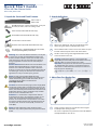
1. Unpack the Switch and Check Contents
AS6712-32X or
AS6812-32X
Rack Mounting Kit—2 front-post brackets, 2 rear-post
brackets, 20 screws, and 2 ear-locking screws
Power Cord (included with AC PSUs only)
Ground Wire (included with DC PSUs only)
Console Cable—RJ-45 to DB-9
DC Power Cable (included with 48 VDC PSU only)
Documentation—Quick Start Guide (this document)
and Safety and Regulatory Information
Warning:
For a safe and reliable installation, use only the
accessories and screws provided with the AS6712-32X,
AS6812-32X. Use of other accessories and screws could
result in damage to the unit. Any damages incurred by
using unapproved accessories are not covered by the
warranty.
Avertissement:
Avertissement: Pour une installation sûre
et fiable, utilisez uniquement les accessoires et les vis
fournies avec le AS6712-32X,AS6812-32X. L’utilisation
d’autres accessoires et vis pourrait endommager l’appareil.
Les dommages causés par l’utilisation d’accessoires non
approuvés ne sont pas couverts par la garantie.
Note:
The switch has the Open Network Install
Environment (ONIE) software installer pre-loaded, but no
switch software image pre-loaded. Information about
compatible switch software can be found at
www.edge-core.com.
Caution:
The switch includes plug-in power supply (PSU)
and fan tray modules that are installed into its chassis. All
installed modules must have a matching airflow direction.
That is, if the installed power modules have a front-to-back
(F2B) airflow direction, all the installed fan tray modules
must also have a F2B airflow direction.
Attention:
Le commutateur comprend des modules
d'alimentation et de bac de ventilateurs installés sur son
châssis. Tous les modules installés doivent avoir une
direction de circulation d'air correspondante. C'est-à-dire
que tous les modules doivent avoir la même direction de
circulation d'air: avant vers arrière (F2B), ou arrière vers
avant (B2F).
Note:
The switch drawings in this document are for
illustration only and may not match your particular switch
model.
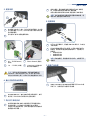
2. Attach the Brackets
Attach each of the front- and rear-post brackets to the
switch using four of the included bracket screws.
Use an additional two screws to secure each of the rear-post
brackets at the mid-point on the sides of the switch.
Use the screws and cage nuts supplied with the rack to
secure the switch in the rack.
Caution:
Installing the switch in a rack requires two
people. One person should position the switch in the rack,
while the other secures it using the rack screws.
Attention:
Deux personnes sont nécessaires pour installer
un commutateur dans un bâti : La première personne va
positionner le commutateur dans le bâti, la seconde va le
fixer avec des vis de montage.
装置の吸排気に必要な領域をマニ ュ アル上に規定し て
いる。
3. Adjust Rear-Post Bracket Ears
Lock the position of the rear-post bracket ears using the
included position-locking screws.
You can also adjust the rear-post bracket ears to fit different
rack depths from 56 cm to 75 cm.
3
1
1
2
1
2
3
1
1
E122019-AP-R04
150200001635A
32-Port 40G Fiber Ethernet Switch
AS6712-32X | AS6812-32X
www.edge-core.com
Quick Start Guide

– 2 –
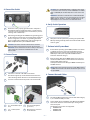
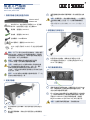
4. Ground the Switch
Ensure the rack is properly grounded and in compliance
with ETSI ETS 300 253. Verify that there is a good electrical
connection to the grounding point on the rack (no paint or
isolating surface treatment).
Attach the grounding wire #14 AWG to the grounding point
on the switch rear panel. Then connect the other end of the
wire to rack ground. For details on grounding the switch
with a 12 VDC PSU in an Open Rack, refer to the Edgecore
ORSA-1U Open Rack Tray Set Installation Guide.
Caution:
The earth connection must not be removed
unless all supply connections have been disconnected.
Attention:
Le raccordement à la terre ne doit pas être retiré
sauf si toutes les connexions d’alimentation ont été
débranchées.
5. Connect Power
Install one or two AC or DC PSUs in the switch.
The switch supports up to two PSUs that must have the
same matching airflow direction as the installed fan trays.
Connect an external AC or DC power source to the PSUs.
36 – 75 VDC Return (blue
wire)
Chassis Ground (yellow-
green wire)
-36
– -75 VDC (brown
wire)
Open Rack tray connector
for 12 VDC PSU
2
1
1
2
2
1
1
2
3
2
1
4
1
3
2
4
Caution:
Use a UL/IEC/EN 60950-1 certified power supply
to connect to a DC converter, and a #14 AWG (for 36–75 VDC
PSU) or #10 AWG (for 12 VDC PSU) wire to connect to a DC
PSU.
Attention:
Utilisez une alimentation certifiée UL/IEC/EN
60950-1 pour le connecter à un convertisseur CC et un câble
AWG #14 (pour -36 VDC à -72 VDC) ou AWG #10 (pour 12
VDC PSU)pour vous connecter à une alimentation CC.
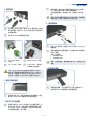
6. Verify Switch Operation
Verify basic switch operation by checking the system LEDs.
When operating normally, the PS1/PS2 and Fan LEDs should
all be on green.
7. Perform Initial System Boot
If the network operating system (NOS) installer is located on
a network server, first connect the RJ-45 Management
(Mgmt) port to the network using Category 5, 5e or better
twisted-pair cable. (Not required if the NOS installer is
located on attached storage.)
Boot the switch. Wait for the ONIE software to locate and
execute the NOS installer, and then wait for the installer to
load the NOS software image.
Subsequent switch boots will bypass ONIE and directly run
the NOS software.
Note:
Refer to the network operating system (NOS) installer
and NOS documentation for details on software options and
set up for ONIE.
8. Connect Network Cables
For the RJ-45 Management port, connect 100-ohm Category
5, 5e or better twisted-pair cable.
Connect DAC cables to the QSFP+ slots. Or first install QSFP+
transceivers and then connect fiber optic cabling to the
transceiver ports.
The following transceivers are supported:
◆
40GBASE-CR4
◆
40GBASE-SR4
◆
40GBASE-LR4
1
1
1
2
2
1
1
2

– 3 –
Hardware Specifications
Note:
As connections are made, check the port status LEDs
to be sure the links are valid.
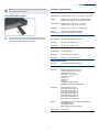
9. View the Product Label
The switch product label is located below the Mgmt and
Console ports on the right side of the front panel. Pull the
label out to view the product information.
1
Switch Chassis
Size (WxDxH) 438.4 x 515 x 43.5 mm (17.26 x 20.28 x 1.73 inches)
Weight AS6712-32X: 9.135 kg (20.12 lb), with two PSUs
AS6812-32X: 9.025 kg (19.9 lb), with two PSUs
Temperature Operating: 0° C to 40° C (32° F to 104° F)
Storage: -40° C to 70° C (-40° F to 158° F)
Humidity Operating: 5% to 95% (non-condensing)
Power
Consumption
AS6712-32X: 355 Watts maximum
AS6812-32X: 310 Watts maximum
AC PSU
Power Rating 100–240 VAC, 50-60 Hz, 400 Watts
AC Input 100–240 VAC, 50-60 Hz, 6–3 A
DC Output 5 VSB @ 3 A, 12 VDC @ 33 A
DC PSU
Power Rating 48 VDC, 400 Watts
DC Input 36–75 VDC, 16 A maximum
DC Output 5 VDC @ 0.5 A, 12 VDC @ 33 A
DC PSU (PSU-12V-650)
DC Input 12 VDC (from Open Rack busbar)
Regulatory Compliances
Emissions EN 55032:2012+AC:2013, Class A
AS/NZS CISPR 32:2013, Class A
CISPR 32:2012, Class A
EN 61000-3-2:2014, Class A
EN 61000-3-3:2013
FCC Class A
VCCI Class A
CE Mark
CCC GB 9254-2008, Class A
BSMI EMI Standard CNS 13438:2006
Immunity EN 55024:2010+A1:2015
IEC 61000-4-2:2008 ED. 2.0
IEC 61000-4-3:2010 ED. 3.2
IEC 61000-4-4:2012 ED. 3.0
IEC 61000-4-5:2014 ED. 3.0
IEC 61000-4-6:2013 ED. 4.0
IEC 61000-4-8:2009 ED. 2.0
IEC 61000-4-11:2004 ED. 2.0
Safety UL (CAN/CSA C22.2 No. 60950-1 & UL60950-1)
CB (IEC/EN60950-1)
CCC GB4943.1-2011
BSMI Safety Standard CNS14336-1
Taiwan RoHS CNS 15663
Quick Start Guide

– 4 –
3
1
1
2
1
装置の吸排気に必要な領域をマニ ュ アル上に規定し て
いる。
2
3
1
1
2
1
1
2
32 端口
AS6712-32X | AS6812-32X

– 5 –
2
1
1
2
3
2
1
4
1
3
2
4
1
1
1
◆
◆
◆
2
2
1
1
2
1

– 6 –
x x
DC PSU (PSU-12V-650)

– 7 –
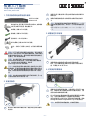
1.
AS6712-32X
AS6812-32X
x2 x2
x20 x2
AC PSU
DC PSU
RJ45 DB-9
DC 48 VDC PSU
AS6712-32X AS6812-32X
ONIE
F2B
F2B
2.
3
1
1
2
1
2
装置の吸排気に必要な領域をマニ ュ アル上に規定し て
いる。
3.
56 cm
75 cm
4.
ETSI ETS 300
253
14 AWG
12 VDC PSU
Edgecore ORSA-1U Open Rack Tray Set
3
1
1
2
1
1
2
32 40G
AS6712-32X | AS6812-32X

– 8 –
5.
1 2 AC DC
2 PSU PSU
AC DC
36 – 75 VDC Return
Chassis Ground
-36 – -75 VDC 12 VDC PSU
DC Converter UL/IEC/EN
60950-1 DC PSU #14
AWG 36 VDC 75 VDC PSU #10
AWG 12 VDC PSU DC PSU
6.
LED
PSU1/PSU2 LED
7.
NOS
5-ohm 5 5e
RJ-45 Mgmt NOS
2
1
1
2
3
2
1
4
1
3
2
4
1
1
1
ONIE NOS
NOS
ONIE NOS
ONIE
NOS NOS
8.
RJ-45 100-ohm 5 5e
DAC
QSFP+
◆
40GBASE-CR4
◆
40GBASE-SR4
◆
40GBASE-LR4
LED
9.
2
2
1
1
2
1

– 9 –
(WxDxH)
438.4 x 515 x 43.5 mm
17.26 x 20.28 x 1.73
AS6712-32X: 9.135 kg 20.12 lb
PSU
AS6812-32X: 9.025 kg 19.90 lb
PSU
: 0° C 40° C 32° F 104° F
: -40° C 70° C -40° F 158° F
: 5% 95%
AS6712-32X: 355
AS6812-32X: 310
AC PSU
100–240 VAC 50-60 Hz 400
AC 100–240 VAC 50-60 Hz 6–3 A
DC 5 VSB @ 3 A 12 VDC @ 33 A
DC PSU
48 VDC 400
DC 36–75 VDC 16 A
DC
5 VDC @ 0.5 A, 12 VDC @ 33 A
DC PSU (PSU-12V-650)
DC 12 VDC
EN 55032:2012+AC:2013, Class A
AS/NZS CISPR 32:2013, Class A
CISPR 32:2012, Class A
EN 61000-3-2:2014, Class A
EN 61000-3-3:2013
FCC Class A
VCCI Class A
CE Mark
CCC GB 9254-2008, Class A
BSMI EMI Standard CNS 13438:2006
EN 55024:2010+A1:2015
IEC 61000-4-2:2008 ED. 2.0
IEC 61000-4-3:2010 ED. 3.2
IEC 61000-4-4:2012 ED. 3.0
IEC 61000-4-5:2014 ED. 3.0
IEC 61000-4-6:2013 ED. 4.0
IEC 61000-4-8:2009 ED. 2.0
IEC 61000-4-11:2004 ED. 2.0
UL (CAN/CSA C22.2 No. 60950-1 & UL60950-
1)
CB (IEC/EN60950-1)
CCC GB4943.1-2011
BSMI Safety Standard CNS14336-1
RoHS
CNS 15663
-
 1
1
-
 2
2
-
 3
3
-
 4
4
-
 5
5
-
 6
6
-
 7
7
-
 8
8
-
 9
9


Edge-Core AS6812-32X ユーザーマニュアル
- タイプ
- ユーザーマニュアル
- このマニュアルも適しています
他の言語で
- English: Edge-Core AS6812-32X User manual