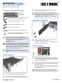
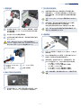
Edge-Core DCS501 は、高性能、低遅延、高スケーラビリティを実現する、レイヤー2/3の 10ギガビット イーサネット スイッチです。このスイッチは、企業、データセンター、およびサービス プロバイダーのネットワークで、帯域幅の厳しいアプリケーションを実行するために設計されています。
DCS501は、最大 48 個の 10 ギガビット イーサネット ポートを備えており、最大 960 Gbps のスループットをサポートします。また、このスイッチは、4つの 40 ギガビット イーサネット ポートまたは 8つの 10 ギガビット イーサネット ポートを備えた、スタッカブルなシャーシで構成されています。このスイッチは、最大 8 台のシャーシをスタックして、最大 384 個の 10 ギガビット イーサネット ポートをサポート
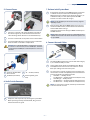


-
 1
1
-
 2
2
-
 3
3
-
 4
4
-
 5
5
-
 6
6
-
 7
7
-
 8
8
-
 9
9


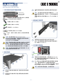
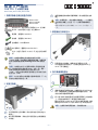
Edge-Core DCS501 は、高性能、低遅延、高スケーラビリティを実現する、レイヤー2/3の 10ギガビット イーサネット スイッチです。このスイッチは、企業、データセンター、およびサービス プロバイダーのネットワークで、帯域幅の厳しいアプリケーションを実行するために設計されています。
DCS501は、最大 48 個の 10 ギガビット イーサネット ポートを備えており、最大 960 Gbps のスループットをサポートします。また、このスイッチは、4つの 40 ギガビット イーサネット ポートまたは 8つの 10 ギガビット イーサネット ポートを備えた、スタッカブルなシャーシで構成されています。このスイッチは、最大 8 台のシャーシをスタックして、最大 384 個の 10 ギガビット イーサネット ポートをサポート
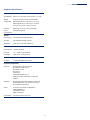
他の言語で
- English: Edge-Core DCS501 User manual
関連論文
-
Edge-Core DCS204 ユーザーマニュアル
-
-
-
-
-
-
-
-
-