
– 1 –
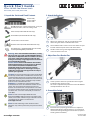
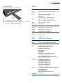
1. Unpack the Switch and Check Contents
AS5710-54X,
AS5712-54X or
AS5812-54X
Rack Mounting Kit—2 front-post brackets, 2 rear-post
brackets, 20 screws, and 2 ear-locking screws
Power Cord (included with AC PSUs only)
Ground Wire (included with DC PSUs only)
Console Cable—RJ-45 to DB-9
DC Power Cable (included with 48 VDC PSU only)
Documentation—Quick Start Guide (this document)
and Safety and Regulatory Information
Warning:
For a safe and reliable installation, use only
the accessories and screws provided with the AS5710-
54X, AS5712-54X,AS5812-54X. Use of other accessories
and screws could result in damage to the unit. Any
damages incurred by using unapproved accessories are
not covered by the warranty.
Avertissement:
Pour une installation sûre et fiable,
utilisez uniquement les accessoires et les vis fournies
avec le AS5710-54X, AS5712-54X,AS5812-54X.
L’utilisation d’autres accessoires et vis pourrait
endommager l’appareil. Les dommages causés par
l’utilisation d’accessoires non approuvés ne sont pas
couverts par la garantie.
Caution:
The switch includes plug-in power supply (PSU)
and fan tray modules that are installed into its chassis. All
installed modules must have a matching airflow direction.
That is, if the installed power modules have a front-to-back
(F2B) airflow direction, all the installed fan tray modules
must also have a F2B airflow direction.
Attention:
Le commutateur comprend des modules
d’alimentation et de bac de ventilateurs installés sur son
châssis. Tous les modules installés doivent avoir une
direction de circulation d’air correspondante. C’est-à-dire
que tous les modules doivent avoir la même direction de
circulation d’air : avant vers arrière (F2B), ou arrière vers
avant (B2F).
Note:
The switch has the Open Network Install
Environment (ONIE) software installer pre-loaded on the
switch, but no switch software image. Information about
compatible switch software can be found at
www.edge-core.com.
Note:
The switch drawings in this document are for
illustration only and may not match your particular switch
model.
2. Attach the Brackets
Attach each of the front- and rear-post brackets to the
switch using four of the included bracket screws.
Use an additional two screws to secure each of the rear-post
brackets at the mid-point on the sides of the switch.
Use the screws and cage nuts supplied with the rack to
secure the switch in the rack.
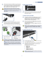
3. Adjust Rear-Post Bracket Ears
Lock the position of the rear-post bracket ears using the
included position-locking screws.
You can also adjust the rear-post bracket ears to fit different
rack depths from 56 cm to 75 cm.
4. Ground the Switch
Ensure the rack is properly grounded and in compliance
with ETSI ETS 300 253. Verify that there is a good electrical
connection to the grounding point on the rack (no paint or
isolating surface treatment).
3
1
1
2
1
2
3
1
1
1
2
1
E022020-CS-R08
150200001634A
www.edge-core.com
54-Port 10G/40G Fiber Ethernet Switch
AS5710-54X | AS5712-54X | AS5812-54X
Quick Start Guide

– 2 –
Attach the grounding wire #14 AWG to the grounding point
on the switch rear panel. Then connect the other end of the
wire to rack ground. For details on grounding the switch
with a 12 VDC PSU in an Open Rack, refer to the Edgecore
ORSA-1U Open Rack Tray Set Installation Guide.
Caution:
The earth connection must not be removed
unless all supply connections have been disconnected.
Attention:
Le raccordement à la terre ne doit pas être retiré
sauf si toutes les connexions d’alimentation ont été
débranchées.
5. Connect Power
Install one or two AC or DC power modules in the switch.
The switch supports up to two PSUs that must have the
same matching airflow direction as the installed fan tray.
Connect an external AC or DC power source to the modules.
36 – 75 VDC Return (blue
wire)
Chassis Ground (yellow-
green wire)
-36
– -75 VDC (brown
wire)
Open Rack tray connector
for 12 VDC PSU
Caution:
Use a UL/IEC/EN 60950-1 certified power supply
to connect to a DC converter, and a #14 AWG (for 36–75 VDC
PSU) or #10 AWG (for 12 VDC PSU) wire to connect to a DC
PSU.
Attention:
Utilisez une alimentation certifiée UL/IEC/EN
60950-1 pour le connecter à un convertisseur CC et un câble
AWG #14 (pour 36 VDC à 75 VDC) pour vous connecter à une
alimentation CC.
2
2
1
1
2
3
2
1
4
1
3
2
4
6. Verify Switch Operation
Verify basic switch operation by checking the system LEDs.
When operating normally, the PSU1/PSU2 and Fan LEDs
should all be on green.
7. Perform Initial System Boot
If the network operating system (NOS) installer is located on
a network server, first connect the RJ-45 Management
(Mgmt) port to the network using 100-ohm Category 5, 5e
or better twisted-pair cable. (Not required if the NOS
installer is located on attached storage.)
Boot the switch. Wait for the ONIE software to locate and
execute the NOS installer, and then wait for the installer to
load the NOS software image.
Subsequent switch boots will bypass ONIE and directly run
the NOS software.
Note:
For switches with ONIE software pre-loaded, refer to
the network operating system (NOS) installer and NOS
documentation for details on software options and set up
for ONIE.
8. Connect Network Cables
For the RJ-45 Management port, connect 100-ohm Category
5, 5e or better twisted-pair cable.
Connect DAC cables to the SFP+/QSFP+ slots. Or first install
SFP+/QSFP+ transceivers and then connect fiber optic
cabling to the transceiver ports.
The following transceivers are supported:
◆
40GBASE-CR4
◆
40GBASE-SR4
◆
10GBASE-CR
◆
10GBASE-SR (ET5402-SR)
◆
1000BASE-SX (ET4201-SX)
◆
1000BASE-LX (ET4201-LX)
Note:
As connections are made, check the port status LEDs
to be sure the links are valid.
1
1
1
2
2
1
1
2
Quick Start Guide

– 3 –
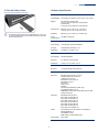
9. View the Product Label
(For AS5712-54X/AS5812-54X only)
The switch product label is located below SFP+ ports 7–12
on left side of the front panel. Pull the label out to view the
product information.
1
Hardware Specifications
Switch Chassis
Size (WxDxH) 438.4 x 473 x 43.4 mm (17.26 x 18.62 x 1.71 inches)
Weight AS5710-54X / AS5712-54X:
8.87 kg (19.56 lb), with two installed PSUs
AS5812-54X:
8.95 kg (19.73 lb), with two installed PSUs
Temperature Operating: 0° C to 40° C (32° F to 104° F)
Storage: -40° C to 70° C (-40° F to 158° F)
Humidity Operating: 5% to 95% (non-condensing)
Power
Consumption
282 Watts maximum
AC PSU
Power Rating 100–240 VAC, 50-60 Hz, 400 Watts
AC Input 100–240 VAC, 50-60 Hz, 6–3 A
DC Output 5 VSB @ 3 A, 12 VDC @ 33 A
48 VDC PSU
Power Rating 48 VDC, 400 Watts
DC Input 36–75 VDC, 16 A maximum
DC Output 5 VDC @ 0.5 A, 12 VDC @ 33 A
12 VDC PSU (PSU-12V-650)
DC Input 12 VDC (from Open Rack busbar)
Regulatory Compliances
Emissions EN 55032:2012+AC:2013, Class A
AS/NZS CISPR 32:2013, Class A
CISPR 32:2012, Class A
EN 61000-3-2:2014, Class A
EN 61000-3-3:2013
FCC Class A
VCCI Class A
CE Mark
KCC (AS5710-54X/AS5712-54X only)
CCC GB 9254-2008, Class A
BSMI EMI Standard CNS 13438:2006 (AS5712-54X/
AS5812-54X only)
Immunity EN 55024:2010+A1:2015
IEC 61000-4-2:2008 ED. 2.0
IEC 61000-4-3:2010 ED. 3.2
IEC 61000-4-4:2012 ED. 3.0
IEC 61000-4-5:2014 ED. 2.0
IEC 61000-4-6:2013 ED. 4.0
IEC 61000-4-8:2009 ED. 2.0
IEC 61000-4-11:2004 ED. 2.0
Safety UL (CAN/CSA C22.2 No. 60950-1 & UL60950-1)
CB (IEC/EN60950-1)
CCC GB4943.1-2011
BSMI Safety Standard CNS14336-1
Taiwan RoHS CNS 15663
Quick Start Guide

– 4 –
3
1
1
2
1
2
3
1
1
1
2
1
2
AS5710-54X | AS5712-54X | AS5812-54X

– 5 –
7
2
1
1
2
3
2
1
4
1
3
2
4
1
1
1
/
/
◆
◆
◆
◆
◆
◆
2
2
1
1
2
1

– 6 –
x x
° ° ° °
° ° ° °
AC PSU
48 VDC PSU
12 VDC PSU (PSU-12V-650)

– 7 –
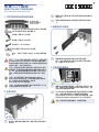
1. 拆開交換器包裝並檢查內容物
AS5710-54X ,
AS5712-54X 或
AS5812-54X
前柱托架 x2、後柱托架附可調固定片 x2、托架螺
絲 x20、後托架固定片位置-定位螺絲 x2
電源線 (僅隨附於 AC PSU)
接地線 (僅隨附於 DC PSU)
控制電纜- RJ45 轉 DB-9
DC 電源線 (僅隨附於 48 VDC PSU)
文件-
快速入門指南
(本文件)及
安全性與法規資
訊
警告:
為了可以更安全的使用與安裝機台,請務必使用
AS5710-54X, AS5712-54X,AS5812-54X 隨貨附贈的配
件,避免導致設備損壞或其他風險產生。 使用未經批准
的配件造成的任何損壞,均不在保修範圍內。
注意:
交換器包含插入式電源供應器以及風扇托盤模
組。所有後部安裝之模組氣流方向,必須一致。意即,
如果安裝的電源供應器有從前至後的氣流方向
(F2B),則所有安裝的風扇托盤模組也必須為前至後的
氣流方向 (F2B)。
說明:
交換器有預載之開放網路安裝程式環境
(ONIE)軟體,但未預載交換器軟體映像檔。有關其他
相容交換器軟體請參閱 www.edge-core.com 網站說
明。
說明:
本文件使用的交換器圖片僅供舉例說明,不一定
與您的交換器外觀完全一致。
2. 安裝交換器
利用四個所附之托架螺絲,將前柱和後柱托架安裝在交
換器上。
額外使用兩個螺絲,將後柱托架各別固定在交換器側邊
中間處。
使用隨機櫃提供的螺絲及籠罩螺帽,將交換器固定在機
櫃上。
3. 調整後柱托架固定片
利用所附的定位螺絲,鎖緊後柱托架固定片位置。
亦可調整後柱托架固定片,以安裝在深度為 56 cm 至
75 cm 不等之機櫃上。
3
1
1
2
1
2
3
1
1
54 埠 10G/40G 乙太網路交換機
AS5710-54X | AS5712-54X | AS5812-54X
快速入門指南

– 8 –
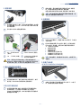
4. 對交換器實施接地
請確保對機架正確實施接地,並確保符合 ETSI ETS 300
253。請確認機架上的接地點的電氣導通狀態良好 (確
保沒有油漆或絕緣表面處理)。
將 14 號 AWG 接地線連接至交換器背面面板上的接地點
上。然後將接地線的另一端連接至機架的接地。 關於如
何連接 12 VDC PSU 至開放式機架連接器,請參閱
Edgecore ORSA-1U Open Rack Tray Set 安裝手冊。
注意:
在斷開所有電源連接前,切勿斷開接地。
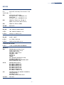
5. 連
在交換器上安裝 1 個或 2 個 AC 或 DC 電源模組。 本交換
器可使用最多 2 個 PSU,且 PSU 的氣流方向必須與安裝
的風扇框相同。
將外部 AC 或 DC 電源連接至模組。
36 – 75 VDC Return
(藍線)
Chassis Ground (黃線)
-36 – -75 VDC (棕線 ) 12 VDC PSU (連接開放
式機架後方的連接器
)
注意:
在 DC Converter 的前端必須使用 UL/IEC/EN
60950-1 認證的電源供應器 連接 DC PSU 。使用 #14
AWG 線 (適用於 36 VDC 至 75 VDC PSU)或 #10
AWG 線 (適用於 12 VDC PSU)連接至 DC PSU。
1
2
1
2
2
1
1
2
3
2
1
4
1
3
2
4
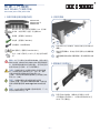
6. 確認交換器操作
透過檢查系統 LED,確認交換器的基本運轉情況。 如運
轉正常,PSU1/PSU2 和風扇 LED 會亮起綠燈。
7. 執行初次系統啟動
若網路作業系統 (NOS)安裝程式位於網路伺服器,先
使用 5-ohm 第 5 類、5e 類或更優之雙絞線電纜,連接
RJ-45 管理 (Mgmt)埠至網路。(若 NOS 安裝程式位
於所附儲存設備中,則不需要。)
啟動交換器。等待 ONIE 軟體找尋並執行 NOS 安裝程
式,並等待安裝程式載入 NOS 軟體映像檔。
之後交換器啟動時,會跳過 ONIE,直接運行 NOS 軟
體。
說明:
關於詳細軟體選項及 ONIE 設定說明,請參閱網
路作業系統 (NOS)安裝程式及 NOS 文件。
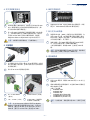
8. 連接網路線
對於 RJ-45 管理埠,請連接 100-ohm 類別 5、5e 或以上
的雙絞線。
連接光纖電纜至收發器連接埠。或直接將 DAC 線連接至
SFP+/QSFP+ 插槽。
支援以下收發器:
◆
40GBASE-CR4
◆
40GBASE-SR4
◆
10GBASE-CR
◆
10GBASE-SR (ET5402-SR)
◆
1000BASE-SX (ET4201-SX)
◆
1000BASE-LX (ET4201-LX)
說明:
完成連接後,請檢查埠狀態 LED,以確保正常連
接。
1
1
1
2
2
1
1
2
快速入門指南

– 9 –
9. 檢視產品標籤
( 僅 AS5712-54X/AS5812-54X 交換器 )
交換器產品標籤,位於 SFP+ 連接埠 7-12 下方、前方面
板左側。拉出標籤即可檢視產品資訊。
1
硬體規格
交換器機箱
尺寸
(WxDxH)
438.4 x 473 x 43.4 mm (17.26 x 18.62 x 1.71 英
吋)
重量
AS5710-54X / AS5712-54X:
8.87 kg (19.56 lb),含兩個安裝之 PSU
AS5812-54X:
8.95 kg (19.73 lb),含兩個安裝之 PSU
溫度 操作 : 0° C 至 40° C (32° F 至 104° F)
儲存 : -40° C 至 70° C (-40° F 至 158° F)
濕度 操作 : 5% 至 95% (無冷凝)
消耗功率 最大 282 瓦
AC PSU
額定功率 100–240 VAC,50-60 Hz,400 瓦
AC 輸入
100–240 VAC, 50-60 Hz, 6–3 A
DC 輸出
5 VSB @ 3 A, 12 VDC @ 33 A
48 VDC PSU
額定功率 48 VDC,400 瓦
DC 輸入 36–75 VDC,最大 16 A
DC 輸出
5 VDC @ 0.5 A, 12 VDC @ 33 A
12 VDC PSU (PSU-12V-650)
DC 輸入 12 VDC (從開放式機架後方的母線取電)
法規符合性
排放
EN 55032:2012+AC:2013, Class A
AS/NZS CISPR 32:2013, Class A
CISPR 32:2012, Class A
EN 61000-3-2:2014, Class A
EN 61000-3-3:2013
FCC Class A
VCCI Class A
CE Mark
KCC ( 僅限 AS5710-54X/AS5712-54X)
CCC GB 9254-2008, Class A
BSMI EMI Standard CNS 13438:2006 ( 僅限
AS5712-54X/AS5812-54X)
電磁耐受性
EN 55024:2010+A1:2015
IEC 61000-4-2:2008 ED. 2.0
IEC 61000-4-3:2010 ED. 3.2
IEC 61000-4-4:2012 ED. 3.0
IEC 61000-4-5:2014 ED. 2.0
IEC 61000-4-6:2013 ED. 4.0
IEC 61000-4-8:2009 ED. 2.0
IEC 61000-4-11:2004 ED. 2.0
安全性
UL (CAN/CSA C22.2 No. 60950-1 & UL60950-
1)
CB (IEC/EN60950-1)
CCC GB4943.1-2011
BSMI Safety Standard CNS14336-1
台灣 RoHS
CNS15663
快速入門指南
-
 1
1
-
 2
2
-
 3
3
-
 4
4
-
 5
5
-
 6
6
-
 7
7
-
 8
8
-
 9
9


