
H3C S6800-54QF & S6800-54HF Switches Installation Quick Start-6W105
H3C S6800-54QF & S6800-54HF 交换机 快速安装指南-6W105
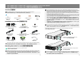
Installation accessories 安装附件介绍
No installation tools are provided with the switch. Prepare them yourself as required.
交换机不随机提供安装工具,请用户根据实际安装需求自己准备安装工具。
Phillips screwdriver
十字螺丝刀
ESD wrist strap
防静电腕带
Marker
记号笔
Tool list 工具参考
Mounting the switch in a rack 安装交换机到机柜
Grounding cable
地线
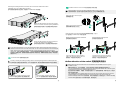
Attach the mounting brackets and chassis rails to the switch
安装挂耳和滑道导轨到交换机
Grounding screw
接地螺钉
Wear an ESD wrist strap, and make sure the strap makes good skin contact and is reliably grounded.
操作者需佩戴防静电腕带,确保防静电腕带与皮肤良好接触,并确认防静电腕带已经良好接地。
!
1
2
Rack-mount rail kit B
(with super-short slide rails) (optional)
超短滑道和导轨(选配)
Rack-mount rail kit C (optional)
滑道和导轨(选配)
Flathead screwdriver
一字螺丝刀
For an LS-6800-54QF-H3 switch, if the rack has a depth (distance between the front and rear rack
posts) in the range of 621 to 793 mm (24.45 to 31.22 in), use mounting brackets and rack-mount rail kit
A. If the rack has a depth in the range of 330 to 505 mm (12.99 to 19.88 in), use mounting
brackets and rack-mount rail kit B (narrow-spacing installation of chassis rails). If the rack has a
depth in the range of 438 to 632 mm (17.24 to 24.88 in), use mounting brackets and rack-mount
rail kit B (wide-spacing installation of chassis rails).
For the other switch models, if the rack has a depth in the range of 621 to 854 mm (24.45 to 33.62
in), use mounting brackets and rack-mount rail kit A. If the rack has a depth in the range of 401 to 634
mm (15.79 to 24.96 in), use mounting brackets and rack-mount rail kit C.
对于LS-6800-54QF-H3机型, 挂耳与长滑道和导轨配合安装适用于机柜前后方孔条间距范围为621
~
793mm。挂耳与超短滑道和导轨配合安装到机柜时,滑道导轨有正向安装和反向安装两种方式:导轨
正向安装适用于机柜前后方孔条间距范围为330
~505mm;导轨反向安装适用于机柜前后方孔条间距
范围为438
~632mm。
对于其他机型,挂耳与长滑道和导轨配合安装适用于机柜前后方孔条间距范围为621
~854mm。挂耳
与滑道和导轨配合安装适用于机柜前后方孔条间距范围为401
~634mm。
Rack-mount rail kit A
(with long slide rails)
长滑道和导轨
Install the mounting brackets near the port side or power module side of the switch as needed. Attach
the chassis rails to the switch based on the mounting bracket installation position and rack depth.
用户可以根据安装场景的需要,将挂耳安装在设备靠近端口侧或靠近电源侧,并根据机柜深度,在交换
机侧面板的对应位置安装滑道导轨。
1
Install the mounting brackets near the power
module side 挂耳安装到靠近电源侧
Attaching the mounting brackets and chassis rails of rack-mount rail kit A to the switch
挂耳与长滑道的导轨配合安装
Install the mounting brackets near the port side
挂耳安装到靠近端口侧
The mounting bracket and slide rail installation procedures are similar for the switches. The following
procedures use an LS-6800-54QF-H3 switch. 交换机各款机型安装挂耳、长滑道或滑道到交换机的方
式相似,此处以产品代码为LS-6800-54QF-H3的机型为例。
Use three screws to secure a mounting bracket at the port side. For the LS-6800-54QF-H3, use four
screws. 产品代码为LS-6800-54QF-H3的机型,挂耳安装在靠近端口侧时,使用四颗螺钉安装挂耳。
其它机型请使用三颗螺钉将挂耳安装在靠近端口侧。
Mounting brackets and M4 screw
前挂耳和M4螺钉
Type A 类型一 Type B 类型二
Cable tie
可拆卸式扎带
M6 screw and cage nut
(user supplied)
M6 螺钉和浮动螺母(用户自备)
Filler module 假面板
Type A 类型一
Type B 类型二

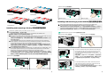
Correctly connecting the switch grounding cable is crucial to lightning protection and EMI protection.
交换机地线的正确连接是交换机防雷、防干扰的重要保障,请使用设备随机提供的保护地线正确接地。
!
Ground the switch 安装地线到交换机
2
Use the primary grounding point at the power
module side 使用主接地点 (靠近电源侧)接地
Use the auxiliary grounding point at the
port side 使用备用接地点 (靠近端口侧)接地
Install the switch in a 19-inch rack 安装交换机到19英寸机柜
3
Before installing cage nuts, mark their installation positions on the rack posts.
安装浮动螺母前,建议用户先使用记号笔在机柜立柱上标注浮动螺母安装位置。
3
Attaching the mounting brackets and chassis rails of rack-mount rail kit B to the switch
(applicable only to an LS-6800-54QF-H3 switch)
挂耳与超短滑道的导轨配合安装(只适用于LS-6800-54QF-H3的机型)
Install a mounting bracket (near the power module
side) and a chassis rail (narrow-spacing installation)
挂耳安装到靠近电源侧、超短滑道的导轨正向安装
Install a mounting bracket (near the port side) and
a chassis rail (wide-spacing installation)
挂耳安装到靠近端口侧、超短滑道的导轨反向安装
Attach cage nuts to the rack posts.
安装浮动螺母到机柜方孔条上
Attach slide rails to the rack posts.
安装滑道到机柜
Mounting brackets near the port side
挂耳安装在靠近端口侧
Mount the switch in the rack (two options)安装交换机到机柜(二选一)
以产品代码为LS-6800-54QF-H3的机型为例
Mounting brackets near the power module side
挂耳安装在靠近电源侧
To use rack-mount rail kit A or C for rack-mounting the switch, make sure the front ends of the long
slide rails or slide rails reach out of the chassis rails. To use rack-mount rail kit B for rack-mounting the
switch, make sure the super-short slide rails slide a minimum length of 90 mm (3.54 in) into the
chassis rails. 为保证设备安装后的稳定性,使用长滑道或滑道和配套的导轨安装完成后,请确保长滑道
或滑道的头部露出导轨。使用超短滑道和配套的导轨安装完成后,请确保超短滑道头部进入导轨的最小
深度为90mm。
Connect the other end of the grounding
cable to the grounding point on the rack
接地线另一端连接到机柜接地点
Connect the other end of the grounding
cable to the grounding point on the rack
接地线另一端连接到机柜接地点
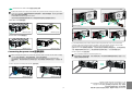
Airflow direction of the switch 交换机的风向设计
Make sure the air inlet and outlet vents are not blocked and the installation site has a good
ventilation system.
请确保交换机的进、出风孔不被遮挡,并将交换机安装在具有良好通风散热系统的环境中。
You can provide airflow for the switch from the port side to the power module side or from the power
module side to the port side by installing different fan trays.
通过配置不同的风扇模块,可提供“端口侧到电源侧”和“电源侧到端口侧”两种气流方向,满足不
同环境下的散热要求。
The LSWM1FANSC and LSPM1FANSA blow air from the power module side to the port side. The
LSWM1FANSCB and LSPM1FANSB draw air from the port side to the power module side.
LSWM1FANSC和LSPM1FANSA为吹风风扇,风向为电源侧进风,端口侧出风;LSWM1FANSCB和
LSPM1FANSB为抽风风扇,风向为端口侧进风,电源侧出风。
4
1
2
3
3
4
4

LSWM1FANSC LSPM1FANSA
5
6
Installing and removing a fan tray 安装/拆卸风扇模块
LSWM1FANSCB
LSPM1FANSB
Remove a fan tray 拆卸风扇模块
!
Follow these guidelines when you install or remove a fan tray:
在安装/拆卸风扇模块时,请注意如下事项:
Make sure the airflow direction of the fan tray is as required by the installation site.
请确认风扇模块气流方向和安装环境的通风要求一致。
The switch comes with the fan tray slots empty. Before powering on the switch, install a fan tray in
each fan tray slot and make sure the installed fan trays are the same model.
交换机出厂时风扇插槽均为空,为保证设备的正常散热,用户必须满配相同型号的风扇模块,否则
禁止交换机上电运行。
For an S6800-54QF (product code LS-6800-54QF-H3), if more than one fan tray fails during
switch operation, do not remove these fan trays simultaneously. Replace one fan tray at a time
and the replacement of each fan tray cannot take more than three minutes.
在S6800-54QF(产品代码LS-6800-54QF-H3)交换机运行过程中,如果有多个风扇模块出现故障,
在更换风扇模块过程中禁止同时拔出多个风扇模块,应按照拔出一个立即更换一个的方式进行,且
单个风扇模块的更换时间不能超过3分钟。
For an S6800-54QF (product codes LS-6800-54QF or LS-6800-54QF-H1) or S6800-54HF, if one
fan tray fails, replace the fan tray as soon as possible and keep the fan tray in the slot before
replacement. If both fan trays fail, finish replacing the fan trays within 1 minute.
在S6800-54QF(产品代码LS-6800-54QF)、S6800-54QF(产品代码LS-6800-54QF-H1)、S6800-
54HF交换机运行过程中,如果一个风扇模块出现故障,请及时进行更换,且更换前需保持故障风扇
模块在位;如果两个风扇模块均出现故障,则必须在1分钟内完成故障风扇模块的更换安装。
Installing and removing a power module 安装/拆卸电源模块
Make sure the airflow direction of the power module is as required by the installation site.
Do not install power modules with different airflow directions on the same switch.
请确认电源模块气流方向和安装环境的通风要求一致。不同型号的电源模块不要混插在同一台交换机上。
For power modules available for the switch, see H3C S6800 Switches Series Installation Guide.
各款交换机支持的电源模块型号,请参见《H3C S6800系列以太网交换机安装指导》。
!
Install and remove a power module 电源模块的安装与拆卸
1
Remove a power module拆卸电源
Install a power module 安装电源
To remove a PSR450-12D power module from the switch, first
remove the DC power cord connector from the power module.
Use a flat-head screwdriver to loosen the screws on the
connector, and then remove the power cord connector from the
power module.
需要注意的是,在拆除PSR450-12D电源模块时,要先拆除直流
电源插头。PSR450-12D电源模块需要先使用一字螺丝刀逆时针
拧下直流电源线插头两侧自带的螺钉,然后将插头向外拔出。
Install a fan tray 安装风扇模块
Method 1 方式一
Method 2 方式二
Method 2 方式二Method 1 方式一
1
2
For a PSR450-12AHD power module, release the jaw of the
cable clamp and open the cable clamp, and then remove the
power cord connector from the power module.
PSR450-12AHD电源模块需要先解开防脱线扣上的卡扣,然后松
开电源线缆上的防脱线扣,最后向外拔出电源线插头。
2
1
3
1
1
1
1
2
2
2
2
1
2
1

Install a filler module 安装假面板
Method 1 方式一
Use a removable cable tie to secure the power cord.
使用可拆卸式扎带固定电源线,以防止电源线脱落。不同型号的电源模块固定电源线方法相同,此处
以固定交流电源线为例示意。
7
Copyright © 2018, New H3C Technologies Co., Ltd.
The information in this document is subject to change without notice.
Copyright © 2018 新华三技术有限公司 版权所有,保留一切权利
本文档中的信息如有更改,恕不另行通知
如需了解产品及安装方面的更多信息,请登录H3C网站 www.h3c.com
Install and remove a filler module 假面板的安装与拆卸
2
Install a filler module in the empty power module slot to prevent dust from entering the chassis and
ensure good ventilation. 若电源模块插槽没有安装电源模块,请及时安装假面板,防止灰尘进入交换机,
同时又保证设备的良好通风散热。
Available filler modules vary by device model.
交换机不同机型使用的假面板有可能不同,请根据实际情况选择合适的假面板安装方式。
Remove a filler module 拆卸假面板
Secure an power cord 固定电源线
Connecting the power cord 连接电源线
Before connecting the power cord, connect the grounding cable and make sure the switch is reliably
grounded.在连接电源线前,需先连接保护地线,保证交换机正确接地。
Connect the power cord to the switch first and then to the power source to avoid bodily injury.
连接电源线时,请先完成电源线与交换机侧的连接,再进行电源线与供电系统的连接,以免造成人身
伤害。
Connect the power cord to the power module 连接电源线
Method 4 方式四
For a PSR450-12AHD power module, slide the cable clamp onto the tie mount, connect the female
connector of the power cord to the power receptacle on the power module, and then close the cable
clamp and slide it forward until it is flush against the edge of the female connector.
连接PSR450-12AHD电源模块的电源线时,先将防脱线扣扣到电源模块自带的固定带上;再将电源线带插
孔的一端插到电源模块的输入插口上;最后使用防脱线扣扣紧电源插头,以防止电源线插头松动。
Method 2 方式二
Method 1 方式一
Method 2 方式二
Method 1 方式一 Method 2 方式二
1
Method 3 方式三
1
1
2
2
2
3
-
 1
1
-
 2
2
-
 3
3
-
 4
4


他の言語で
- English: H3C S6800-54QF
関連論文
-
H3C S6800-54QT Installation, Quick Start
-
-
-
-
-
-
-
-
-