Wren 14XLCT55 Operation and Maintenance Manual
- タイプ
- Operation and Maintenance Manual

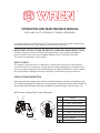
OPERATION AND MAINTENANCE MANUAL
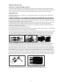
IMPORTANT INSTRUCTIONS ON RECEIPT (OPEN PACKAGE INSPECTION)
①
②
③
④
⑤
⑥
⑦
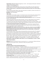
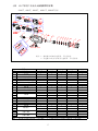
ITEM
BODY
360 S° 180° WIVEL JOINT×
QUICK COUPLING
FIXING HOOK
360°SWIVEL REACTION ARM
SQUARE DRIVE
DRIVE RETAINER
NAME
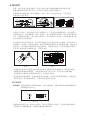
SAFETY FIRST!
The hydraulic torque wrench is a power tool. Read all the instructions, warnings and
cautions before every operation. Comply with the safety precautions to avoid personal
injury or equipment damage while operating this tool! Neither WREN,nor its distributors
are responsible for damage to the tool caused by unsafe and/or faulty operations.
Carefully inspect all components for shipping damages. If any shipping damage is
found, notify the carrier at once. Shipping damage is NOT covered by warranty.
The carrier is responsible for all repairs.
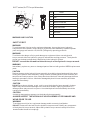
alloy and super high strength alloy steel for increased strength, intensity and durability of the
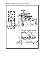
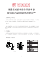
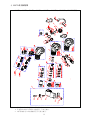
MXTA series, Square Drive Torque Wrenches:
It is operating manual of MXTA and XLCT series Torque Wrench, please read carefully
with following instruction, warning and Caution before using Tool.
1
MXTA AND XLCT HYDRAULIC TORQUE WRENCHES
tool. Double acting hydraulic design, Can lock and loosen the bolt connection, widely suitable for
PRODUCTIONS DESCRIPTION
-
QUICK RELEASE ARM
①
②
③
④
⑤
⑥
⑧
⑦
FIG1
large torque bolt and disassembly, High repeatability, a precise design is with accuracy +3%.
-

2
WARNING AND CAUTION
WARNING
WARNING
WARNING
CAUTION
To avoid personal injuries and/or equipment damage, be sure that every hydraulic
component of the hydraulic torque wrench, hydraulic hose assembly, hydraulic power
To minimize the danger of injury and damage to equipment: Never use a hydraulic
torque wrench without a hydraulic gauge to indicate the working pressure. The hydraulic
Immediately replace any worn or damaged parts of the tool with genuine WREN replacement
parts .
Reduce damage to the hydraulic hose assembly by avoiding sharp bends and kinks when
routing the hydraulic hose assembly. Using a bent or kinked hydraulic hose assembly will
cause severe back-pressure. Also, sharp bends and kinks will internally damage the hose
leading to premature failure. A kinked or damaged hydraulic hose assembly should be
replaced immediately.
DO NOT drop heavy objects, crush, or drive over the hydraulic hose assembly. A sharp
impact may cause internal damage to the hose wire strands. Applying pressure to a
damaged hose may cause it to rupture. A crushed hydraulic hose assembly should be
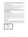
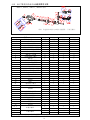
ITEM
NAME
①
②
③
④
⑤
⑥
⑧
⑦
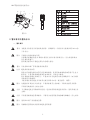
LOW PROFILE CASSETTE
PIN
POWER HEAD
QUICK COUPLING
REACTION ARM
LINK PIN
RATCHET
360° 360 SWIVEL JOINT× °
⑨
360°SWIVEL JOINT
XLCT series,XLCT Porque Wrenches:
SIDE
①
⑤
⑥
⑧
⑦
④
③
②
⑨
SAFETY FIRST!
pack and gauge are rated for 10,000 PSI (700kg/cm2) operating pressure.
gauge is a window to show what is happening in the hydraulic system.
DO NOT exceed the allowable maximum torque of the hydraulic torque wrench.
CAUTION
replaced immediately.
Avoid high temperature exposure to the hydraulic hose assembly.
CAUTION
ALWAYS INSPECT THE HYDRAULIC HOSE ASSEMBLY FOR DAMAGE AND
WEAR PRIOR TO USE.
To avoid personal injuries, equipment damage and/or warranty invalidation:
DO NOT: Remove the shroud from the hydraulic torque wrench. Modify any component
of the hydraulic torque wrench. Adjust the hydraulic torque wrench safety relief valve
WARNING
located inside the swivel couplings.
XLTC

3
CAUTION
CAUTION
The incorrect system connection may cause failure and injury. Before connecting the
hydraulic torque wrench and hydraulic hose assembly to the assembled power pack,
make sure the hydraulic torque wrench swivel couplings, hose couplings and hydraulic
power pack couplings are clean and free of debris.
LOOSE OR DIRTY COUPLERS WILL CAUSE TOOL NOT TO OPERATE PROPERLY
DO NOT use old or damaged sockets. use the wrong size sockets.
WARNING
Only use a high quality socket. The socket must measure up to standard ISO-2725 and
ISO-1174 or DIN3129 and DIN3121 or ASME-B107.2/1995. Never use a chrome plated
socket.
WARNING
Always use a pin to lock the socket with the square drive in order to avoid the socket from
falling off.
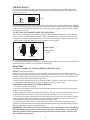
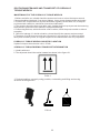
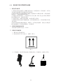
PROPER SAFETY ATTIRE
When operating hydraulic equipment, use proper safety equipment and clothing. Consult
with your company’s safety representative to obtain this information.
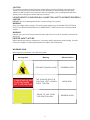
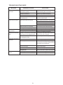
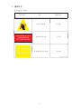
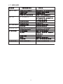
WARNING SIGN
Warning signs are shown in the following table
IF DRIVE STICKS OUT RIGHT,
IT'S SET FOR TIGHTEN.
LEFT. IT'S SET FOR LOOSE!
LOCK REACTION
ARM BEFORE
USING TOOL!
warning table
Meaning
Affixed Position
WORK HEAD
REVERSE LEVER
PROHIBIT USING BY HAND
PRIOR TO USE,FIXED
THE REACTION ARM
REVERSE LEVER
THE SQUARE DRIVE IN
POSITION,LEFT LOOSEN,
RIGHT TIGHTEN

4
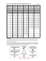
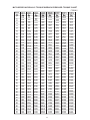
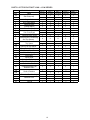
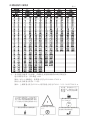
Bolting
REMARKS:
Strength Grade
4.8 6.8 8.8 10.9
Min breaking
strength
392MPa 588MPa 784MPa 941MPa
Material
Q235(SS41) 35(S35C) 35CrMo(SCM3) 42CrMo(SCM4)
Thread
22 7 69 10 98 14 137 17 165
24 10 98 14 137 21 206 25 247
27 14 137 21 206 29 284 35 341
30 18 176 28 296 41 402 58 569
32 23 225 34 333 55 539 78 765
36 32 314 48 470 70 686 100 981
41 45 441 65 637 105 1029 150 1472
46 60 588 90 882 125 1225 200 1962
50 75 735 115 1127 150 1470 210 2060
55 100 980 150 1470 180 1764 250 2453
60 120 1176 180 1764 220 2156 300 2943
65 155 1519 240 2352 280 2744 390 3826
70 180 1764 280 2744 320 3136 450 4415
75 230 2254 350 3430 400 3920 570 5592
80 280 2744 420 4116 480 4704 670 6573
85 360 3528 530 5149 610 5978 860 8437
90 410 4018 610 5978 790 7742 1100 10791
95 510 4998 760 7448 900 8820
100 580 5684 870 8526 1100 10780
105 660 6468 1000 9800 1290 12642
110 750 7350 1100 10780 1500 14701
115 830 8143 1250 12250 1850 18130
120 900 8820 1400 13720 2250 22050
130 1080 10584 1650 16170 2500 24500
145 1400 13720 2050 20090
155 1670 16366 2550 24990
175 2030 19894 3050 29890
mm
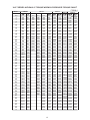
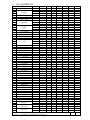
1. All recommendations above are in accordance with the Germany standard (DIN).
2.The figures above represent the maximum bolt torque; the recommended torque is
12.9
1176MPa
40 GrNiMoA(SNCM)
23 225
36 363
49 480
69 680
93 911
120 1176
180 1764
240 2352
250 2450
300 2940
370 3626
470 4606
550 5390
680 6664
850 8330
1050 10290
1350 13230
14
16
18
20
22
24
27
30
33
36
39
42
45
48
52
56
60
64
68
72
76
80
85
90
100
110
120
M
KGM N.m
KGM N.m KGM N.m KGM N.m
KGM N.m
Torque values
Torque values
Torque values
Torque values Torque values
FORM 1
BOLTING TIGHTENING FORCE RECOMMENTED CHART
80% of these chart figures.
3.The recommended tightening torque is 80% of the chart figure above. For example;
for bolt M52 the strength grade is 8.8 therefore, the torque is 4704*80% = 3763Nm
4.The recommended loosening torque is 150% of the tighting torque. For example; the
tightening torque is 3763*150%(200%) = 5645(7526) Nm.

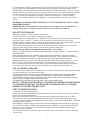
Connect the IBT square drive hydraulic torque wrench and hydraulic power pack with the
proper twin line hydraulic hose assembly making sure all connections are proper and snug.
If the couplings are not properly mated the hydraulic torque wrench may not operate.
HYDRAULIC TORQUE WRENCH SET UP
OPERATION SECTION
PREPARATION
1. Make certain of the size of the nut or bolt head, material, strength grade and determine
ALWAYS ABIDE BY THE MANUFACTURERS/ENGINEERS PROCEDURES.
2. Determine the torque value needed and then determine the corresponding pressure of
3. Inspect the hydraulic torque wrench set. Connect the hydraulic torque wrench, hydraulic
hydraulic connections are securely connected. Verify that the hydraulic hose assembly is
4. Connecting the hydraulic torque wrench:
The hydraulic torque wrench and torque wrench power pack are connected by a 10,000 PSI
the desired torque.
the torque wrench pump. This can be found in the Pressure - Torque Conversion Chart that
was provided with the hydraulic torque wrench.
hose assembly and the hydraulic power pack in to a hydraulic circuit. Ensure that all
not kinked, crushed or damaged.
operation pressure twin line hydraulic hose assembly.
FIG(3)
FIG(5)
FIG(4)
Convex joint
Concave joint
FIG(6)
FIG(7)
when in use (completely stuck, according
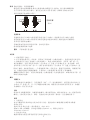
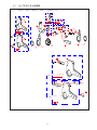
To connect the hydraulic hose assembly to the swivel as shown below Insure the connectors
are fully engaged and screwed snugly together (FIG4) ,do as photo (4) show can ensure
connection successfully.This way can open the check valve,make the oil circuit smoothly,
otherwise,the check valve will lock under the steel ball without top connection,as a result
the oil circuit will not pass through, the wrench will not operate, The reason is that the
connection is filled with pressure,in order to protect the tool, the top swivel will automatic
drain oil. Right way to do correction, please loose the hydraulic hose, check all of the steel
ball inside the quick coupler, please try to press the steel ball by hand, as normal the ball will
be flexible when you touch it, if it is hard, you may find a hammer to knock the ball until your
finger can press the ball(FIG6), during releasing the pressure in the system,please be more
carefully with the spray oil, to avoid stain your clothes!Perfectly done, You may reconnect
the quick coupler again. If you prefer to card set quick coupler, it will be more easy, ref the
arrow on the coupler, put the male coupler into the female coupler directly.
5
RIGHT
Fully screwed the quick coupler, to ensure joint
tooth completely.
to the code of the arrow reverse operation)

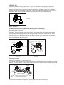
FOR MXTA SERIES
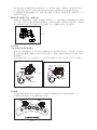
To remove the square, disengage the drive retainer assembly by depressing the center
round button and gently pulling on the square end of the square drive, The square drive
will slide easily out.
To insert the square drive in the tool(FIG8),place the drive in the desired direction, engage
drive and bushing splines, then twist drive and bushing until ratchet spline can be engaged.
Push drive through ratchet. Depress drive retainer button, engage retainer with drive and
release button to lock.
TO SETTING THE SQUARE DRIVE FOR ROTATION:
The position of the square drive when looking at the shroud will determine if the hydraulic
torque wrench is set to loosen or tighten. When the square drive extends to the left when
looking at the shroud, the hydraulic torque wrench is set to loosen. When the square drive
extends to the right, the hydraulic torque wrench is set to tighten.
5. Connecting the hydraulic pump:
The hydraulic torque wrench and torque wrench power pack are connected by a 10,000 PSI
operation pressure twin line hydraulic hose assembly.
IMPORTANT
TO AVOID HYDRAULIC TORQUE WRENCH MALFUNCTION:
DO NOT reverse connectors.
When use the hydraulic hose with quick coupler ,the connection should follow from the
hydraulic torque wrench advance side to the pump advance side, from the hydraulic torque
wrench retract side to the pump retract side, Each quick coupler should be inserted in the
end, then screw the threaded sleeve by hand.
Carefully check whether the quick coupler is reliable, Carefully check the oil in the pump,
no oil shortage operation. Please plug the power electric power supply.
OPERATING THE HYDRAULIC TORQUE WRENCH
1. Put the wrench to the ground.
2. open the pump power switch,start the pump,then press the lock button to confirm the
pump is running normally.
3. By pushing the remote control advance button, the rear of the hydraulic torque wrench
will be pushed back until the reaction arm will make contact with the reaction point.
4. Continue to hold the advance button as the square drive turns until you hear an audible
“click” which will signify the hydraulic cylinder inside the hydraulic torque wrench is fully
extended and will not turn the socket further. Release button.
5. Continuing to hold the remote control advance button, will result in a rapid buildup of
pressure to the point where the gauge reads what the hydraulic power pack was preset to
prior to applying the hydraulic torque wrench.
IMPORTANT: The reading of full preset pressure after the cylinder is extended DOES
NOT INDICATE that this pressure (torque) is applied to the bolt/nut. It only indicates
that the cylinder is fully extended and cannot turn the socket further, until the tool
automatically resets itself.
6
FIG8
FIG9
Button
Drive Retainer
Square Drive
lossing
tightening
Right is tight.
Left is loose.

6. Releasing the remote control button will automatically retract the cylinder. The hydraulic
torque wrench will automatically reset itself and the operator will hear an audible “click”
indicating he can again push the remote control button and the square drive will turn. Each
time the cylinder is extended and retracted, it is called a cycle. Successive cycles are made
until the tool “stalls” at the preset Torque/PSI with an accuracy of +/-3%. Repeatability
is +/-1%. Please repeat again and again, make the wrench turn without loading,
observe the wrench tightening or loosening, no abnormalities, can be put into the
socket.
IMPORTANT: ALWAYS ATTEMPT ONE FINAL CYCLE TO INSURE THE “STALL” POINT
HAS BEEN REACHED.
REMARKS: When the hydraulic torque wrench not in use,you may turn off the lock
button,if long time no using the wrench,please shut off the motor switch.
ADJUST THE PRESSURE
Setting the pressure on the hydraulic power pack.
To set the pressure on the pump, follow this procedure.
Loosen the locking ring below the “T” handle on the hydraulic power pack’s external pressure
regulator. Then, turn the “T” handle counterclockwise until it turns freely and easily.
Turn the hydraulic power pack on. Using the hydraulic power pack remote pendant, push the
advance switch (or button on the air hydraulic power pack) and hold it.
While holding the hydraulic power pack in the advance mode, slowly turn the “T” handle
clockwise and observe the hydraulic power pack pressure gauge rise.
NOTE: Always adjust the regulator pressure UP - never down.
When your gauge reaches the predetermined pressure, stop turning the “T” handle and let
the gauge settle.
If the pressure continues to rise above the predetermined pressure, release the back
pressure slightly by turning the “T” handle counterclockwise. Then, depress the advance
switch on the remote and slowly bring pressure up to the predetermined pressure.
When the pressure is correct, turn the pump off and tighten the locking ring which is under
the “T” handle. This sets the pump pressure, which determines torque wrench output.
Once your target pressure is set and locked, cycle the hydraulic power pack once more to
ensure that your pressure setting did not change as you tightened the locking ring.
THE LOOSENING PROCESS
1. Set the pump to 10000 PSI. Change the drive to the loosening mode, assuring the reaction
2. Press and hold the remote control advance button. Pressure will decrease as the
3. Release the remote control advance button and the cylinder automatically retracts,
4. Repeat this process until the fastener can be removed by hand.
arm abuts squarely on a solid reaction point.
socket begins to turn. As the cylinder extends fully, you will hear an audible “click”.
at which time you again hear the audible “click”.
NOTE: IF THE BOLT/NUT DOES NOT LOOSEN WITH THE ABOVE PROCEDURES,
IT IS AN INDICATION THAT YOU REQUIRE A LARGER HYDRAULIC TORQUE
WRENCH TO LOOSEN THE BOLT/NUT.
THE TIGHTENING PROCESS
1. hydraulic torque wrench setting
Firstly, according to the design requirements set torque,If no design torque, please ref the
80% of the recommended torque.
Way: the setting torque=(the recommended torque of these chart figures)×(80%-90%)
For example:the recommended tightening torque is 90% of the chart figure above. For
example; for bolt M48 the strength grade is 8.8 therefore, the torque is 3920×90% = 3528Nm
2. Pump pressure setting
According to a desired torque value and the wrench model to set the pressure of the pump.
For example 8.8 grade、M48bolt,the setting torque is 3528N.m, if you prefer to WR-3IBT
wrench,you may find the torque is 3528N.m, the pump pressur is 54Mpa,so the pump
pressure setting is 54Mpa.
7
3. Confirm the wrench is tightening, put the wrench on the nut, perform it until the nut does
not move far.

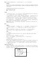
LOCKED-ON
Should the hydraulic torque wrench be “locked-on” after the final cycle, push down the
remote control advance button once more (to build pressure) and while maintaining this
pressure, pull back on the accuracy assurance pawl lever (located on the side of the tool).
Release the remote control advance button, while continuing to push down on the accuracy
assurance lever (this will allow the hydraulic torque wrench to be removed easily).
press down
FIG10
XLCT SERIES
The Ratchet link and the power head assembly and disassembly
Insert the hex ratchet links. The low profile hex ratchet links are inserted and removed from
the power head as follows:
The “hook” described by the link’s drive plate is inserted around the fixed pin of the power
head and the link is swung down to rest along the base of the power head cylinder. At this
point, the link pin holes of the power head and link will align. Insert the link pin to secure.
Pull out the pin, pull up the power head, and then along the groove direction, disassembly
the power head and the ratchet link.
assembly
disassembly
1. insert direction
2. press to the end
3. insert the pin
1. pull out the
2. take the power
3. the hook groove automatic
FIG 11 FIG 12
Direction position
Setting for tightening or loosening the nut:
The position of the tool relative to the nut determines whether the action will tighten or loosen
the nut. The power stroke of the piston rod will always turn the hex ratchet toward the shroud.
FIG 13
8
The nut turns clockwise for tightening and counterclockwise for loosening.
direction
combined pin
head up
down back, separated from
the wrench
lossing
tightening
Low profile hydraulic torque
wrench direction diagram

Preparation Determined the loose(tighten) nut size , select appropriated power head and
ratchet link and reducer inserts.
CONNECT THE POWER PACK
Use twin hose to Connect the high pump pressure outlet(H OR A) with the high pressure
outlet of hydraulic wrench,low pressure outlet of the pump to low pressure outlet of the
hydraulic torque wrench。Insert the quick couple sleeve into the end,then screw tighting
by no space.
Check carefully whether the twin hose joint connection is reliable, please be sure the oil in
enough.The pump power plug power supply.
WARNING No oil shortage !
TEST RUN
1. Put the wrench assembly in space, first start to finish, Check whether the rotating ratchet
normal return or not, if the rotation is not normal, Maybe the hook position does not
correspond between the power head and ratchet link,open to check.
2. Turn on the pump power switch, start the pump, then press the lock button to confirm the
pump is running normally.
3. By pushing the remote control advance button, the rear of the hydraulic torque wrench
will be pushed back until the reaction arm will make contact with the reaction point.
4. Continue to hold the advance button as the cassette turns until you hear an audible “click”
which will signify the hydraulic cylinder inside the hydraulic torque wrench is fully extended
and will not turn the socket further. Release button.
5. Continuing to hold the remote control advance button, will result in a rapid buildup of
pressure to the point where the gauge reads what the hydraulic power pack was preset to
prior to applying the hydraulic torque wrench.
IMPORTANT: The reading of full preset pressure after the cylinder is extended DOES
NOT INDICATE that this pressure (torque) is applied to the bolt/nut. It only indicates
that the cylinder is fully extended and cannot turn the socket further, until the tool
automatically resets itself.
6. Releasing the remote control button will automatically retract the cylinder. The hydraulic
torque wrench will automatically reset itself and the operator will hear an audible “click”
indicating he can again push the remote control button and the cassette will turn. Each time
the cylinder is extended and retracted, it is called a cycle. Successive cycles are made until
the tool “stalls” at the preset Torque/PSI with an accuracy of +/-3%. Repeatability is +/-1%.
Please repeat again and again, make the wrench turn without loading, observe the
wrench tightening or loosening,no abnormalities, can be put into the nut directly.
IMPORTANT: ALWAYS ATTEMPT ONE FINAL CYCLE TO INSURE THE “STALL” POINT
HAS BEEN REACHED.
REMARKS: When the hydraulic torque wrench not in use, ,you may turn off the lock button,
if long time no using the wrench, please shut off the pump motor switch.
9
OPERATION
Setting the pressure on the hydraulic power pack:
To set the pressure on the pump, follow this procedure:
Loosen the locking ring below the “T” handle on the hydraulic power pack external pressure
regulator. Then, turn the “T” handle counterclockwise until it turns freely and easily.
Turn the hydraulic power pack on. Using the hydraulic power pack remote pendant, push the
advance switch (or button on the air hydraulic power pack) and hold it.
While holding the hydraulic power pack in the advance mode, slowly turn the “T” handle
clockwise and observe the hydraulic power pack pressure gauge rise.
Note: Always adjust the regulator pressure UP - never down.
When your gauge reaches the predetermined pressure, stop turning the “T” handle and
let the gauge settle.
If the pressure continues to rise above the predetermined pressure, release the back
pressure slightly by turning the “T” handle counterclockwise. Then, depress the advance
switch on the remote and slowly bring pressure up to the predetermined pressure.

10
When the pressure is correct, turn the pump off and tighten the locking ring which is under
the “T” handle. This sets the pump pressure, which determines torque wrench output.
Once your target pressure is set and locked, cycle the hydraulic power pack once more to
ensure that your pressure setting did not change as you tightened the locking ring.
THE LOOSENING PROCESS
1. Set the pump to 10000 PSI. Change the drive to the loosening mode, assuring the reaction
arm abuts squarely on a solid reaction point.
2. Press and hold the remote control advance button. Pressure will decrease as the cassette
begins to turn. As the cylinder extends fully, you will hear an audible “click”.
3. Release the remote control advance button and the cylinder automatically retracts, at
which time you again hear the audible “click”.
4. Repeat this process until the fastener can be removed by hand.
NOTE: IF THE BOLT/NUT DOES NOT LOOSEN WITH THE ABOVE PROCEDURES, IT IS
AN INDICATION THAT YOU REQUIRE A LARGER HYDRAULIC TORQUE WRENCH TO
LOOSEN THE BOLT/NUT.
THE TIGHTENING PROCESS
1. Draulic torque wrench setting
Firstly, according to the design requirements set torque, If no design torque, please ref the
80% of the recommended torque.
Way: the setting torque=(the recommended torque of these chart figures)×(80%-90%)
For example: The recommended tightening torque is 90% of the chart figure above. For
example; for bolt M48 the strength grade is 8.8 therefore, the torque is 3920*90% = 3528Nm
2. Pump pressure setting
According to a desired torque value and the wrench model to set the pressure of the pump.
For example 8.8 grade、M48 bolt, the setting torque is 3528N.m, if you prefer to WR-4LOW
wrench, you may find the torque is 3528N.m, the pump pressure is 42Mpa, so the pump
pressure setting is 42Mpa.
3.Confirm the wrench is tightening,put the wrench on the nut,perform it until the nut does not
move far.
LOCKED-ON
Should the hydraulic torque wrench be “locked-on” after the final cycle, push down the
remote control advance button once more (to build pressure) and while maintaining this
pressure, pull back on the accuracy assurance pawl lever (located on the side of the tool).
Release the remote control advance button, while continuing to push down on the accuracy
assurance lever (this will allow the hydraulic torque wrench to be removed easily).
FIG 14
press down
direction

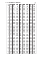
MXTA SERIES HYDRAULIC TORQUE WRENCH PRESSURE-TORQUE CHART
FORM 2
11
Model
10
11
12
13
14
15
16
17
18
19
20
21
22
23
24
25
26
27
28
29
30
31
32
33
34
35
36
37
38
39
40
41
42
43
44
45
46
47
48
49
50
51
52
53
54
55
56
57
58
59
60
61
62
63
64
65
66
67
68
69
70
7
8
9
183
209
236
262
288
314
341
367
393
419
446
472
498
524
551
577
603
629
656
682
708
734
761
787
813
839
866
892
918
944
971
997
1023
1049
1076
1102
1128
1154
1181
1207
1233
1259
1286
1312
1338
1364
1391
1417
1443
1469
1496
1522
1548
1574
1601
1627
1653
1679
1706
1732
1758
1784
1811
1837
1031
1096
1160
1225
1289
1353
1418
1482
1547
1611
1676
1740
1805
1869
1934
1998
2063
2127
2191
2256
2320
2385
2449
2514
2578
2643
2707
2772
2836
2900
2965
3029
3094
3158
3223
3287
3352
3416
3481
3545
3610
3674
3738
3803
3867
3932
3996
4061
4125
4190
4254
4319
4383
4448
4512
451
515
580
644
709
773
838
902
967
1075
1182
1290
1397
1505
1612
1720
1828
1935
2043
2150
2258
2365
2473
2580
2688
2796
2903
3011
3118
3226
3333
3441
3548
3656
3764
3871
3979
4086
4194
4301
4409
4516
4624
4732
4839
4947
5054
5162
5269
5377
5484
5592
5700
5807
5915
6022
6130
6237
6345
6452
6560
6668
6775
6883
6990
7098
7205
7313
7420
7528
752
860
967
1078
1232
1386
1540
1694
1848
2002
2156
2310
2464
2618
2772
2926
3080
3234
3388
3542
3696
3850
4004
4158
4312
4466
4620
4774
4928
5082
5236
5390
5544
5698
5852
6006
6160
6314
6468
6622
6776
6930
7084
7238
7392
7546
7700
7854
8008
8162
8316
8470
8624
8778
8932
9086
9240
9394
9548
9702
9856
10010
10164
10318
10472
10626
10780
1551
1773
1994
2216
2438
2659
2881
3103
3324
3546
3768
3989
4211
4433
4654
4876
5098
5319
5541
5763
5984
6206
6428
6649
6871
7093
7314
7536
7758
7979
8201
8423
8644
8866
9088
9309
9531
9753
9974
10196
10418
10639
10861
11083
11304
11526
11748
11969
12191
12413
12634
12856
13078
13299
13521
13743
13964
14186
14408
14629
14851
15073
15294
15516
10284
10665
11046
11427
11808
12189
12570
12951
13332
13713
14094
14475
14855
15236
15617
15998
16379
16760
17141
17522
17903
18284
18665
19046
19427
19807
20188
20569
20950
21331
21712
22093
22474
22855
23236
23617
23998
24378
24759
25140
25521
25902
26283
26664
2666
3047
3428
3809
4190
4571
4952
5332
5713
6094
6475
6856
7237
7618
7999
8380
8761
9142
9523
9903
3472
3968
4464
4960
5456
5952
6448
6945
7441
7937
8433
8929
9425
9921
10417
10913
11409
11905
12401
12898
13394
13890
14386
14882
15378
15874
16370
16866
17362
17858
18354
18850
19347
19843
20339
20835
21331
21827
22323
22819
23315
23811
24307
24803
25299
25796
26292
26788
27284
27780
28276
28772
29268
29764
30260
30756
31252
31749
32245
32741
33237
33733
34229
34725
10428
11123
11818
12514
13209
13904
14599
15295
15990
16685
17380
18076
18771
19466
20161
20856
21552
22247
22942
23637
24333
25028
25723
26418
27114
27809
28504
29199
29895
30590
31285
31980
32676
33371
34066
34761
35456
36152
36847
37542
38237
38933
39628
40323
41018
41714
42409
43104
43799
44495
45190
45885
46580
47276
47971
48666
4866
5561
6256
6952
7647
8342
9037
9733

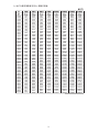
MXTA SERIES HYDRAULIC TORQUE WRENCH PRESSURE-TORQUE CHART
FORM 3
12
Model
1000
1200
1400
1600
1800
2000
2200
2400
2600
2800
3000
3200
3400
3600
3800
4000
4200
4400
4600
4800
5000
5200
5400
5600
5800
6000
6200
6400
6600
6800
7000
7200
7400
7600
7800
8000
8200
8400
8600
8800
9000
9200
9400
9600
9800
10000
134
161
188
215
242
268
295
322
349
376
403
430
457
483
510
537
564
591
618
645
672
698
725
752
779
806
833
860
887
914
940
967
994
1021
1048
1075
1102
1129
1155
1182
1209
1236
1263
1290
1317
1344
328
394
459
525
590
656
721
787
852
918
984
1049
1115
1180
1246
1311
1377
1443
1508
1574
1639
1705
1770
1836
1901
1967
2033
2098
2164
2229
2295
2360
2426
2491
2557
2623
2688
2754
2819
2885
2950
3016
3082
3147
3213
3278
547
656
766
875
985
1094
1203
1313
1422
1532
1641
1750
1860
1969
2079
2188
2297
2407
2516
2626
2735
2844
2954
3063
3173
3282
3391
3501
3610
3720
3829
3938
4048
4157
4267
4376
4485
4595
4704
4814
4923
5032
5142
5251
5361
5470
1096
1253
1409
1566
1723
1879
2036
2193
2349
2506
2662
2819
2976
3132
3289
3446
3602
3759
3915
4072
4229
4385
4542
4699
4855
5012
5168
5325
5482
5638
5795
5951
6108
6265
6421
6578
6735
6891
7048
7204
7361
7518
7674
7831
783
940
1127
1352
1578
1803
2029
2254
2480
2705
2931
3156
3381
3607
3832
4058
4283
4509
4734
4959
5185
5410
5636
5861
6087
6312
6538
6763
6988
7214
7439
7665
7890
8116
8341
8567
8792
9017
9243
9468
9694
9919
10145
10370
10595
10821
11046
11272
1937
2324
2712
3099
3487
3874
4261
4649
5036
5424
5811
6198
6586
6973
7361
7748
8135
8523
8910
9298
9685
10072
10460
10847
11235
11622
12009
12397
12784
13172
13559
13946
14334
14721
15109
15496
15883
16271
16658
17046
17433
17820
18208
18595
18983
19370
2523
3028
3532
4037
4541
5046
5550
6055
6559
7064
7568
8073
8577
9082
9586
10091
10595
11100
11604
12109
12613
13118
13622
14127
14631
15136
15641
16145
16650
17154
17659
18163
18668
19172
19677
20181
20686
21190
21695
22199
22704
23208
23713
24217
24722
25226
3535
4242
4949
5656
6363
7070
7777
8485
9192
9899
10606
11313
12020
12727
13434
14141
14848
15555
16262
16970
17677
18384
19091
19798
20505
21212
21919
22626
23333
24040
24747
25454
26162
26869
27576
28283
28990
29697
30404
31111
31818
32525
33232
33939
34647
35354

13
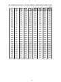
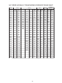
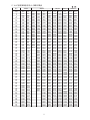
XLCT SERIES HYDRAULIC TORQUE WRENCH PRESSURE-TORQUE CHART
FORM 4
2XLCT
30XLCT
14XLCT
8XLCT4XLCT
Model
Bolt Size Range
34-36
41
46-65
Mpa
N.m
N.m
N.m
N.m N.m
N.m
N.m
N.m
N.m
N.m
N.m
10
11
12
13
14
15
16
17
18
19
20
21
22
23
24
25
26
27
28
29
30
31
32
33
34
35
36
37
38
39
40
41
42
43
44
45
46
47
48
49
50
51
52
53
54
55
56
57
58
59
60
61
62
63
64
65
66
67
68
69
70
7
8
9
232
265
299
332
365
398
432
465
498
531
565
598
631
665
698
731
764
798
831
864
897
931
964
997
1030
1064
1097
1130
1164
1197
1230
1263
1297
1330
1363
1396
1430
1463
1496
1530
1563
1596
1629
1663
1696
1729
1762
1796
1829
1862
1895
1929
1962
1995
2029
2062
2095
2128
2162
2195
2228
2261
2295
2328
241
275
310
344
379
413
448
482
517
551
586
620
655
689
724
758
793
827
862
896
931
965
1000
1034
1069
1103
1138
1172
1207
1241
1276
1310
1345
1379
1414
1448
1483
1517
1552
1586
1621
1655
1690
1724
1759
1793
1828
1862
1897
1931
1966
2000
2035
2069
2104
2138
2173
2207
2242
2276
2311
2345
2380
2414
585
669
752
836
920
1003
1087
1171
1255
1338
1422
1506
1589
1673
1757
1840
1924
2008
2092
2175
2259
2343
2426
2510
585
669
752
836
920
1003
1087
1171
1255
1338
1422
1506
1589
1673
1757
1840
1924
2008
2092
2175
2259
2343
2426
2510
2594
2677
2761
2845
2929
3012
3096
3180
3263
3347
3431
3514
3598
3682
3766
3849
3933
4017
4100
4184
4268
4351
4435
4519
4603
4686
4770
4854
4937
5021
1003
1087
1171
1255
1338
1422
1506
1589
1673
1757
1840
1924
2008
2092
2175
2259
2343
2426
2510
2594
2677
2761
2845
2929
3012
3096
3180
3263
3347
3431
3514
3598
3682
3766
3849
3933
4017
4100
4184
4268
4351
4435
4519
4603
4686
4770
4854
4937
5021
5105
5188
5272
5356
5440
5523
5607
5691
5774
5858
585
669
752
836
920
647
739
832
924
1017
1109
1202
1294
1387
1479
1572
1664
1757
1849
1942
2034
2127
2219
2312
2404
2497
2589
2682
2774
2867
2959
3052
3144
3237
3329
3422
3514
3607
3699
3792
3884
3977
4069
4162
4254
4347
4439
4532
4624
4717
4809
4902
4994
5087
5179
5272
5364
5457
5549
5642
5734
5827
5919
6012
6104
6197
6289
6382
6474
1094
1250
1407
1563
1719
1876
2032
2188
2344
2501
2657
2813
2970
3126
3282
3439
3595
3751
3907
4064
4220
4376
4533
4689
4845
5002
5158
5314
5470
5627
5783
5939
6096
6252
6408
6565
6721
6877
7033
7190
7346
7502
7659
7815
7971
8128
8284
8440
8596
8753
8909
9065
9222
9378
9534
9691
9847
10003
10159
10316
10472
10628
10785
10941
10092
10260
10428
10597
10765
10933
11101
11269
11438
11606
11774
1177
1345
1513
1682
1850
2018
2186
2354
2523
2691
2859
3027
3195
3364
3532
3700
3868
4037
4205
4373
4541
4709
4878
5046
5214
5382
5550
5719
5887
6055
6223
6391
6560
6728
6896
7064
7232
7401
7569
7737
7905
8073
8242
8410
8578
8746
8914
9083
9251
9419
9587
9756
9924
1852
2117
2381
2646
2910
3175
3440
3704
3969
4233
4498
4762
5027
5292
5556
5821
6085
6350
6615
6879
7144
7408
7673
7938
8202
8467
8731
8996
9260
9525
9790
10054
10319
10583
10848
11113
11377
11642
11906
12171
12435
12700
12965
13229
13494
13758
14023
14288
14552
14817
15081
15346
15611
15875
16140
16404
16669
16933
17198
17463
17727
17992
18256
18521
4188
4786
5385
5983
6581
7180
7778
8376
8975
9573
10171
10769
11368
11966
12564
13163
13761
14359
14958
15556
16154
16753
17351
17949
18548
19146
19744
20343
20941
21539
22138
22736
23334
23932
24531
25129
25727
26326
26924
27522
28121
28719
29317
29916
30514
31112
31711
32309
32907
33506
34104
34702
35301
35899
36497
37095
37694
38292
38890
39489
40087
40685
41284
41882
4459
5096
5733
6370
7007
7644
8281
8918
9555
10192
10829
11467
12104
12741
13378
14015
14652
15289
15926
16563
17200
17837
18474
19111
19748
20385
21022
21659
22296
22933
23570
24207
24845
25482
26119
26756
27393
28030
28667
29304
29941
30578
31215
31852
32489
33126
33763
34400
35037
35674
36311
36948
37585
38223
38860
39497
40134
40771
41408
42045
42682
43319
43956
44593

14
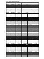
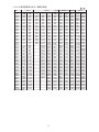
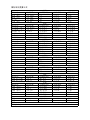
XLCT SERIES HYDRAULIC TORQUE WRENCH PRESSURE-TORQUE CHART
FORM 4
Model
Bolt Size Range
34-36
41
46-65
ft.lbs
psi
ft.lbs ft.lbs
ft.lbsft.lbs ft.lbs ft.lbsft.lbs ft.lbs
ft.lbsft.lbs
2XLCT
4XLCT
8XLCT
14XLCT
30XLCT
1000
1200
1400
1600
1800
2000
2200
2400
2600
2800
3000
3200
3400
3600
3800
4000
4200
4400
4600
4800
5000
5200
5400
5600
5800
6000
6200
6400
6600
6800
7000
7200
7400
7600
7800
8000
8200
8400
8600
8800
9000
9200
9400
9600
9800
10000
169
203
237
270
304
338
372
406
440
473
507
541
575
609
642
676
710
744
778
812
845
879
913
947
981
1015
1048
1082
1116
1150
1184
1217
1251
1285
1319
1353
1387
1420
1454
1488
1522
1556
1589
1623
1657
1691
1017
1052
1087
1122
1157
1192
1227
1262
1298
1333
1368
1403
1438
1473
1508
1543
1578
1613
1648
1683
1719
1754
175
210
245
280
315
350
385
421
456
491
526
561
596
631
666
701
736
771
806
842
877
912
947
982
426
511
596
681
766
852
937
1022
1107
1192
1277
1362
1447
1533
1618
1703
1788
1873
426
511
596
681
766
852
937
1022
1107
1192
1277
1362
1447
1533
1618
1703
1788
1873
1958
2043
2128
2214
2299
2384
2469
2554
2639
2724
2809
2894
2980
3065
3150
3235
3320
3405
3490
3575
3661
426
511
596
681
766
852
937
1022
1107
1192
1277
1362
1447
1533
1618
1703
1788
1873
1958
2043
2128
2214
2299
2384
2469
2554
2639
2724
2809
2894
2980
3065
3150
3235
3320
3405
3490
3575
3661
3746
3831
3916
4001
4086
4171
4256
470
564
658
752
846
940
1034
1128
1222
1317
1411
1505
1599
1693
1787
1881
1975
2069
2163
2257
2351
2445
2539
2633
2727
2822
2916
3010
3104
3198
3292
3386
3480
3574
3668
3762
3856
3950
4044
4138
4232
4326
4421
4515
4609
4703
795
954
1113
1272
1431
1590
1749
1908
2067
2226
2385
2544
2703
2861
3020
3179
3338
3497
3656
3815
3974
4133
4292
4451
4610
4769
4928
5087
5246
5405
5564
5723
5882
6041
6200
6359
6518
6677
6835
6994
7153
7312
7471
7630
7789
7948
855
1026
1197
1368
1539
1710
1881
2052
2223
2395
2566
2737
2908
3079
3250
3421
3592
3763
3934
4105
4276
4447
4618
4789
4960
5132
5303
5474
5645
5816
5987
6158
6329
6500
6671
6842
7013
7184
7355
7526
7697
7868
8040
8211
8382
8553
1346
1615
1884
2153
2422
2692
2961
3230
3499
3768
4037
4306
4575
4844
5113
5383
5652
5921
6190
6459
6728
6997
7266
7535
7804
8074
8343
8612
8881
9150
9419
9688
9957
10226
10495
10765
11034
11303
11572
11841
12110
12379
12648
12917
13186
13456
3043
3652
4260
4869
5477
6086
6694
7303
7911
8520
9128
9737
10345
10954
11562
12171
12779
13388
13996
14605
15213
15822
16430
17039
17647
18256
18865
19473
20082
20690
21299
21907
22516
23124
23733
24341
24950
25558
26167
26775
27384
27992
28601
29209
29818
30426
3240
3888
4536
5184
5832
6480
7127
7775
8423
9071
9719
10367
11015
11663
12311
12959
13606
14254
14902
15550
16198
16846
17494
18142
18790
19438
20085
20733
21381
22029
22677
23325
23973
24621
25269
25917
26564
27212
27860
28508
29156
29804
30452
31100
31748
32396

15
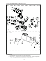
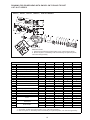
1MXTA、 3 、5 、8 10 20 25 35 SERIESMXTA MXTA MXTA、 MXTA、 MXTA、 MXTA、 MXTA
INSTRUCTION:
3. #1 Body assembly and 5-1# piston assembly are not detachable parts.
2. Quick coupler C1 assembly and C2 assembly are optional parts, own interchange ability.
MXTA SERIES DRAWING AND PARTS LIST
1. Swivel B1 and B2 are optional parts, own interchange ability.

16
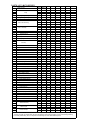
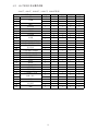
PARTS LIST--MXTA SERIES
Model Number
1MXTA
3MXTA
5MXTA 8MXTA 10MXTA 20MXTA 25MXTA
35MXTA
Item
Name
Quantity
1a
Body
1b 1 1 1 1 1 1 1
1c 1
2
Retaining Ring of Body
1
3
O-Ring/U-Ring for Body
1 1 1 1 1 1 1 1
4
O-Ring for Piston Housing
5a
5b 1 1 1
5c 1 1 1 1 1
5a- 1
Piston Rod Assembly
5b- 1 1 1 1
5c- 1 1 1 1 1 1
5- 2
Wearable Ring for Piston Rod
1 1 1 1 1 2 2 2
5- 3
Retaining Ring
1 1 1 2 1
5- 4
O-Ring for Piston Rod
1 1 1 1 1 1 1 1
6
O-Ring for End Cap
1 1 1 1 1 1 1 1
7
Retaining Ring for End Cap
1 1 1 1 1 1 1 1
8a
End Cap
1 1 1 1 1 1 1
8b
8c
1
9 1 1 1 1 1 1 1 1
9-1
Reaction Arm Assembly
1 1 1 1 1 1 1 1
9-2
Screw
1 1 1 1 1 1 1 1
9-3
Reaction Arm Fixer 1 1 1 1 1 1 1 1
9-4
Compressed Spring for Reaction Arm
1 1 1 1 1 1 1 1
9-5
Reaction Arm Cover
1 1 1 1 1 1 1 1
9- 6
Pin for Reaction Arm Cover
1 1 2 2 2 2 2 2
10
2 2 2 2 2 2 2 2
11
Pin for Body
1 1 1 1 1 1 1 1
12
Tension Spring for Reaction Pawl
1 1 1 1 1 1 1 1
13
Reaction Pawl Pin
1 1 1 1 1 1 1 1
14
Reaction Pawl
1 1 1 1 1 1 1 1
15
Button Lever(Left)
1 1 1 1 1 1 1 1
16
Screw for Button Lever
2 2 2 2 2 2 2 2
17
Button Lever(Right)
1 1 1 1 1 1 1 1
18
Drive Sleeve Spline
2 2 2 2 2 2 2 2
19
Circlip
2 2 2 2 2 2 2 2
20
Square Drive
1 1 1 1 1 1 1 1
A
Drive Retainer
1 1 1 1 1 1 1 1
21
Drive Retainer Screw
22
Drive Pin
1 1 1 1 1 1 1 1
23
Roll Pin for Drive Pawl Primary
1 1 1 1 1 1 1 1
24
Tension Spring for Drive Pawl Prmary
2 2 2 2 2 2 2 2
25
Drive Plate Pin
1 1 1 1 1 1 1 1
26
Drive Pawl Prmary
1 1 1 1 1 1 1 1
27
Drive Pawl Secondary
1 1 1 1 1 1 1 1
28
Compressed Spring Drive Pawl Secondary
2 1 2 2 1 1 1 1
29
Roll Pin for Compressed Spring Drive Pawl Secondary
1 1 1 1
30
Ratchet Spline
1 1 1 1 1 1 1 1
31
Drive Plate
2 2 2 2 2 2 2 2
32
Shroud
1 1 1 1 1 1 1 1
33
Screw for Cover Plate
4 4 4 4 4 4 4 4
B1
Swivel Assembly
1 1 1 1 1 1 1 1
B2 1 1 1 1 1 1 1 1
C1 -1
Male Coupler
1 1 1 1 1 1 1 1
C2 -1
1 1 1 1 1 1 1 1
C1 -2
Female Coupler
1 1 1 1 1 1 1 1
C2 -2
1 1 1 1 1 1 1 1
QuantityQuantityQuantityQuantityQuantityQuantityQuantity
Piston Assembly
Reaction Arm
Screw
INSTRUCTION:
3. #1 Body assembly and 5-1# piston assembly are not detachable parts.
2. Quick coupler C1 assembly and C2 assembly are optional parts, own interchange ability.
1. Swivel B1 and B2 are optional parts, own interchange ability.

17
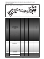
ASSEMBLING DRAWING FOR RATCHET LINK--XLCT SERIES
2 4 8 14 30XLCT、 XLCT、 XLCT、 XLCT、 XLCT SERIES

18
PARTS LIST FOR RATCHET LINK---LOW SERIES
Model Number
2XLCT
4XLCT 8XLCT 14XLCT 30XLCT
Item
Name
Quantity
Quantity
Quantity
Quantity
Quantity
1a
Side Plate(Left)
1 1 1 1
1b
2
Copper Belt
2 2
3 Drive Plate(Right) 1 1 1 1 1
4 Reaction Block 1 1 1 1 1
5 Ratchet Spline 1 1 1 1 1
6 Drive Plate(Left) 1 1 1 1 1
7a
Side Plate(Right)
1 1 1 1
7b 1
8
Reaction Block Screw
4 4 4 4 4
9
Screw(Reaction Pawl Bushing
4 4 4 2 2
10a
Top Spacer
1 1 1 1
10b 1
11
Roll Pin for Top Spacer
1 1 1 1
12
Drive Pin for Drive Plate
1 1 1 1 1
13
Roll Pin for Drive Plate
2 2 2 2 2
14
Drive Pin Spring
1 1 1 1 1
15 Drive Pawl 1 1 1 1 1
16 Spring Seat 1
17
Compressed Spring
1 1 1 1 1
18
Drive Pawl Primary
1 1 1 1 1
19 Pin for Side Plate 1 1 1 1 1
20
Compressed Spring for
1 1 1 1 1
21a
Shaft of Rotation
1 1 1
21b 1 1
22
Reaction Pawl Bushing
1 2 2 1 1
23a
Reaction Pawl
1 1 1 1
23b 1
24 Shroud 1 1 1 1 1
And Top Spacer)
Reaction Pawl

19
2 4 8 14 30XLCT、 XLCT、 XLCT、 XLCT、 XLCT SERIES
Model Number
2XLCT-D
Ⅱ
4XLCT -D
Ⅱ
8XLCT-D
Ⅱ
14XLCT-D
Ⅱ
30XLCT-D
Ⅱ
Item
Name
Quantity
Quantity Quantity Quantity Quantity
1
Body
1 1 1 1 1
2
Casing Cap of Body
1 1 1 1
3
U-Ring for Body
1 1 1 1 1
4
Piston Rod
1 1 1 1 1
5
O-Ring for Piston Rod and End Cap
2 2 2 2 2
6
Retaining Ring for Piston Rod and End Cap
1 2 2 2 2
7
U-Ring for Piston Rod
1 1 1 1 1
8
End Cap
1 1 1 1 1
9
End Cap Screw
2 2 2 2
10
Screw of Body
8 8 8 8 8
11
Rod End
1 1 1 1 1
12a
Fixed Pin Upper
1 1 1
12b 1 1
13
Retaining Ring for Fixed Pin Upper
2 2 2
14
Screw for Fixed Pin Upper
2 2
15
Screw with Spring
1 1 1 1 1
16
Link Pin
1 1 1 1 1
17
Draw Ring
1 1 1 1 1
B1
Swivel
1 1 1 1 1
B2 1 1
C1 -1
Male Coupler
1 1 1 1 1
C2 -1
1 1 1 1 1
C1 -2
Female Coupler
1 1 1 1 1
C2 -2
1 1 1 1 1
DRAWING FOR POWER HEAD WITH SWIVEL ON TOP AND ITS PART
LIST-XLCT SERIES
INSTRUCTION:
2. Quick coupler C1 assembly and C2 assembly are optional parts, own interchange ability.
1. Swivel B1 and B2 are optional parts, own interchange ability.
INSTRUCTION:
2. Quick coupler C1 assembly and C2 assembly are optional parts,
1. Swivel B1 and B2 are optional parts, own interchange ability.
own interchange ability.

20
Model Number
2XLCT-D
Ⅲ
4XLCT-D
Ⅲ
8XLCT-D
Ⅲ
14XLCT-D
Ⅲ
Item
Name
Quantity Quantity Quantity Quantity
1
Body
1 1 1 1
2
U-Ring for Body
1 1 1 1
3 Piston Rod 1 1 1 1
4
O-Ring for Piston Rod and End Cap
2 2 2 2
5
Retaining Ring for Piston Rod and End Cap
1 2 2 2
6
U-Ring for Piston Rod
1 1 1 1
7
O-Ring for End Cap
2 1 1 2
8
Screw of Side End Cap
2 1 1 2
9 End Cap 1 1 1 1
10
Screw of Top End Cap
2 1 1 2
11
End Cap Screw
2 2 2
12
Screw of Body
8 8 8 8
13
Swivel
1 1 1 1
14
0-Ring for The Swivel
6 6 6 6
15
Retainer Ring for The Swive
2 2 2 2
16
Screw for The Swivel
4 2 2 4
17
Swivel Joint
1 1 1 1
18
Steel Ball
1 1 1 1
19
Spring Pedestal
1 1 1 1
20
Spring
1 1 1 1
21
Plug
1 1 1 1
24 Rod End 1 1 1 1
25a
Fixed Pin Upper
1 1 1
25b 1
26
Retaining Ring for Fixed Pin Upper
2 2 2
27 Screw for Fixed Pin Upper 2
28
Screw
2 1 1 1
29 Screw with Spring 1 1 1 1
30 Link Pin 1 1 1 1
31 Draw Ring 1 1 1 1
32 Copper Gasket 2
C1 -1
Male Coupler
1 1 1 1
C2 -1
1 1 1 1
C1 -2
Female Coupler
1 1 1 1
C2 -2
1 1 1 1
DRAWING FOR POWER HEAD WITH SWIVEL IN BACKSIDE AND ITS PART
2 4 8 14XLCT、 XLCT、 XLCT、 XLCT SERIES
LIST-XLCT SERIES
INSTRUCTION:
quick coupler c1 assembly and c2 assembly are optional parts, own interchange ability.
INSTRUCTION:
Quick coupler C1 assembly and C2 assembly are optional
parts, own interchange ability.
ページが読み込まれています...
ページが読み込まれています...
ページが読み込まれています...
ページが読み込まれています...
ページが読み込まれています...
ページが読み込まれています...
ページが読み込まれています...
ページが読み込まれています...
ページが読み込まれています...
ページが読み込まれています...
ページが読み込まれています...
ページが読み込まれています...
ページが読み込まれています...
ページが読み込まれています...
ページが読み込まれています...
ページが読み込まれています...
ページが読み込まれています...
ページが読み込まれています...
ページが読み込まれています...
ページが読み込まれています...
ページが読み込まれています...
ページが読み込まれています...
ページが読み込まれています...
ページが読み込まれています...
ページが読み込まれています...
ページが読み込まれています...
ページが読み込まれています...
ページが読み込まれています...
ページが読み込まれています...
ページが読み込まれています...
-
 1
1
-
 2
2
-
 3
3
-
 4
4
-
 5
5
-
 6
6
-
 7
7
-
 8
8
-
 9
9
-
 10
10
-
 11
11
-
 12
12
-
 13
13
-
 14
14
-
 15
15
-
 16
16
-
 17
17
-
 18
18
-
 19
19
-
 20
20
-
 21
21
-
 22
22
-
 23
23
-
 24
24
-
 25
25
-
 26
26
-
 27
27
-
 28
28
-
 29
29
-
 30
30
-
 31
31
-
 32
32
-
 33
33
-
 34
34
-
 35
35
-
 36
36
-
 37
37
-
 38
38
-
 39
39
-
 40
40
-
 41
41
-
 42
42
-
 43
43
-
 44
44
-
 45
45
-
 46
46
-
 47
47
-
 48
48
-
 49
49
-
 50
50


Wren 14XLCT55 Operation and Maintenance Manual
- タイプ
- Operation and Maintenance Manual
関連論文
その他のドキュメント
-
Casio W-U5, W-U6 ユーザーマニュアル
-
Philips SC51/51 Product Datasheet
-
Genius Scorpion M8-610 ユーザーマニュアル
-
-
Greenlee LPK1230, LPK1240 12-ton Crimping Tools-Chinese ユーザーマニュアル
-
-
Enerpac VE42QM-115 Repair Service Instructions
-
-
Shimano FD-4603 Service Instructions
-
Liebherr SGNef 3036 Comfort Assembly And Installation Instructions