Preparación
Preparación de la videocámara
Para obtener más información, consulte el manual de instrucciones suministrado
con la videocámara.
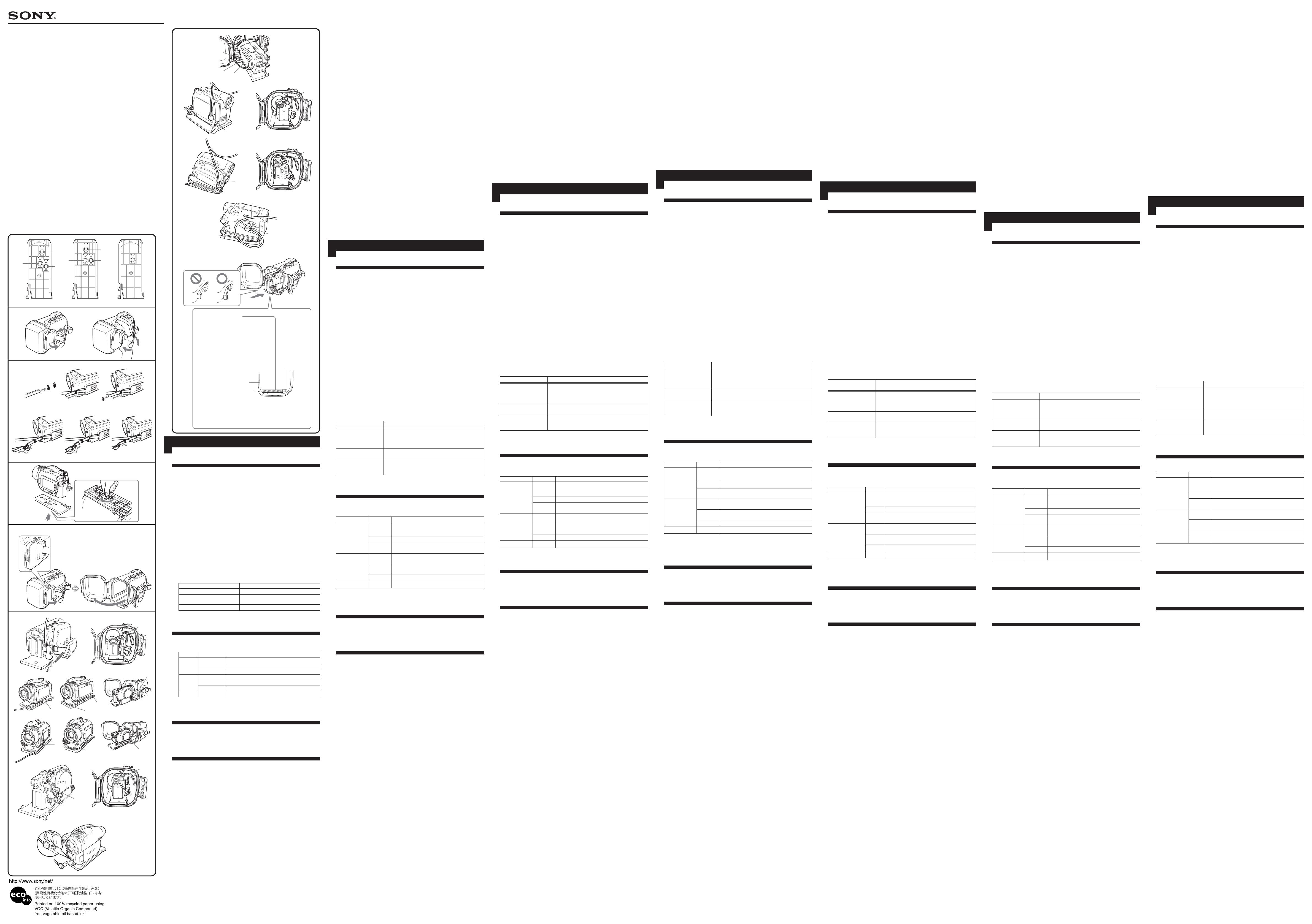
1 Quite el filtro, el objetivo de conversión, la tapa del objetivo y la
correa para el hombro de la videocámara.
Cuando utilice los modelos DCR-HC43/HC42/HC39/HC33/HC32/HC22/
HC21/HC19/HC17, abra el obturador del objetivo.
2 Instale la batería.
Instale una batería completamente cargada.
3Inserte el medio.
Cuando utilice los modelos HDR-HC3, DCR-HC96/HC94/HC90/HC46/
HC44/HC43/HC42/HC39/HC36/HC35/HC33/HC32/HC26/HC24/HC23/
HC22/HC21/HC19/HC17
Inserte una cinta de videocasete y un “Memory Stick Duo”. Algunos modelos
no admiten el “Memory Stick Duo”. En ese caso, inserte una cinta de
videocasete. Para obtener más información, consulte el manual de
instrucciones suministrado con la videocámara.
Cuando utilice los modelos DCR-DVD905/DVD805/DVD755/DVD705/
DVD605/DVD505/DVD405/DVD404/DVD305/DVD304/DVD205/
DVD105
Inserte un disco y un “Memory Stick Duo”. Algunos modelos no admiten el
“Memory Stick Duo”. En ese caso, inserte un disco. Para obtener más
información, consulte el manual de instrucciones suministrado con la
videocámara.
Cuando utilice los modelos DCR-DVD803/DVD703/DVD653/DVD602/
DVD403/DVD203/DVD202/DVD103/DVD92
Inserte un disco.
Desbloquee la lengüeta de seguridad del “Memory Stick Duo” y del
videocasete y déjelos listos para que puedan grabar imágenes.
Cerciórese de que la cinta, el disco del “Memory Stick Duo” y el disco duro
tengan espacio suficiente para grabar imágenes.
Cerciórese de que el disco no esté finalizado.
4 Fije el anillo de prevención de reflejos en la rosca para fijación de
filtros de la videocámara.
5 Gire el panel LCD y repliéguelo hacia la videocámara con la
pantalla LCD encarada hacia fuera.
6 Ajuste las funciones, tales como el enfoque y la iluminación a
AUTO.
A Selección de la zapata de montaje de la cámara
1 Elija la zapata de montaje y el número de acuerdo con la tabla
siguiente.
2 Alinee la placa roscada para trípode con el número elegido en la
zapata de montaje y presione dicha placa hasta que haga clic en
su lugar.
Al salir de fábrica, la placa roscada para trípode está fijada en la posición 1 de
la zapata de montaje A.
B Preparación del portacámara deportivo
1 Ajuste la correa de la empuñadura.
Sujetando el portacámara deportivo de manera que las puntas de sus dedos
puedan tocar fácilmente el botón START/STOP, el botón de telefoto, el botón
de gran angular y el botón PHOTO, ajuste la longitud de la correa.
2 Fije la correa para el hombro.
C Instalación de la videocámara
Ponga el interruptor POWER de la videocámara en la posición “OFF (CHG)” y
deje la alimentación del portacámara deportivo apagada.
1 Fije la zapata de montaje de la videocámara.
Alinee la posición roscada de la zapata de montaje con la rosca para trípode
de la parte inferior de la videocámara. Cuando utilice los modelos HDR-HC3/
DCR-DVD905/DVD805/DVD505/DVD405/DVD404/SR100/SR90, fije la
zapata de montaje después de abrir la cubierta de la toma.
Utilice las parte metálicas de la correa para el hombro, como se muestra en la
ilustración.
2 Abra las hebillas.
1 Manteniendo el botón de desbloqueo 1 en el sentido de la flecha, deslice la
corredera abierta 2 y abra la hebilla.
2 Abra la parte posterior del cuerpo.
3 Recubra el vidrio frontal con solución antiniebla para objetivos.
Aplique 2 o 3 gotas de la solución antiniebla para objetivos suministrada en la
superficie interior del vidrio frontal del portacámara deportivo. Para mejorar
la efectividad antiniebla, utilice el desecador suministrado. Para obtener más
información, consulte el apartado “Desecador” del manual de instrucciones
suministrado.
4 Elimine las materias extrañas, tales como el polvo, la arena o los
pelos de la junta tórica, de la ranura y de cualquier superficie
que esté en contacto. Después, engrase uniformemente la junta
tórica.
Si cerrase el cuerpo con tales materias presentes, estas áreas podrían dañarse y
provocar la infiltración de agua.
5Conecte la clavija e instale la videocámara.
Dependiendo del modelo de videocámara, inserte firmemente la clavija de
control remoto y audio en la toma A/V o en la toma A/V OUT.
Cuando instale la videocámara en el portacámara deportivo, alinee la zapata
de montaje de la cámara con la guía de la mitad frontal del cuerpo y empuje la
parte trasera de la zapata de montaje de la cámara hasta que haga clic.
Nota
Cerciórese de mantener el portacámara deportivo en posición horizontal
cuando instale la zapata de montaje de la cámara.
La instalación de la zapata de montaje de la cámara en vertical puede dañar la
zapata de montaje de la cámara y la parte frontal del cuerpo. Asegúrese de no
cubrir con el cable el objetivo, la pantalla LCD, el visor, la palanca de zoom ni
el botón PHOTO.
Cuando utilice los modelos HDR-HC3 (consulte la ilustración C-5-A)
1 Desplace hacia los bordes la cubierta de la toma.
2 Conecte la clavija.
3 Tras instalar la videocámara en el portacámara deportivo, ajuste el cable.
(Enganche el cable en el portacables.)
Cuando utilice los modelos DCR-DVD905/DVD505 (consulte la
ilustración C-5-B)
1 Conecte la clavija.
2 Repliegue la cubierta de la clavija y engánchela a la pieza más saliente de la
zapata de montaje de la cámara.
3 Ajuste el cable en la ranura de la zapata de montaje de la cámara.
4 Cuando instale la videocámara, asegúrese de que el cable no se engancha
con las partes del portacámara deportivo.
Cuando utilice los modelos DCR-DVD805/DVD405/DVD404 (consulte
la ilustración C-5-C)
1 Conecte la clavija.
2 Tras instalar la videocámara en el portacámara deportivo, ajuste el cable en
la ranura de la zapata de montaje de la cámara.
3 Cuando instale la videocámara, asegúrese de que el cable no se engancha
con las partes del portacámara deportivo.
Cuando utilice los modelos DCR-DVD755/DVD705/DVD605/DVD305/
DVD304/DVD205/DVD105 (consulte la ilustración C-5-D)
1 Conecte la clavija.
1
2
1
2
4
3
2
1
1
2
3
1
2
3
Sports Pack Preparation Guide
Guide de préparation du caisson
Vorbereitung des Sports Pack
Guía de preparación del portacámara deportivo
Voorbereidingshandleiding voor sportbehuizing
Bruksanvisning
Guida per la preparazione della custodia sportiva
Guia de preparação da embalagem desportiva
Правила подготовки спортивного футляра
스포츠팩 준비 가이드
2-667-230-01(1)
SPK-HCB
© 2006 Sony Corporation Printed in Japan
1
2
C
1
2
1
MC ND
DCR-HC41
2
3
HDR-HC3 DCR-HC96/HC90/HC41
DCR-DVD505/DVD405
DCR-DVD403/DVD203
4
5
6
A
1
2
A 1
B
1
START/STOP Photo
2
C
1
HDR-
HC3
DCR-DVD505/DVD405/SR100
2
1 1 2
2
3
2
3
4
O
O
5
/ A/V
A/V OUT
B
1
2
3
A
5
3
1
2
1
2
1
2
3
G
F
25 DCR-HC41
M30 62
HDR-HC3 DCR-DVD505/DVD405
DCR-SR100
M30 43 DCR-DVD403/DVD203/HC96/HC90
1 DCR-DVD505/DVD405
A2DCR-HC90
3 DCR-HC41
1 DCR-DVD403/DVD203
B2DCR-HC96
3 HDR-HC3
C
DCR-SR100
English
Preparing
Preparing the Video Camera
For details, please refer to the operating instructions supplied with your video
camera.
1 Remove filter, conversion lens, lens cap or the shoulder strap
from the video camera.
When using DCR-HC43/HC42/HC39/HC33/HC32/HC22/HC21/HC19/
HC17 models, open the lens shutter.
2 Install the battery pack.
Attach a fully recharged battery.
3 Insert the media.
When using HDR-HC3, DCR-HC96/HC94/HC90/HC46/HC44/HC43/
HC42/HC39/HC36/HC35/HC33/HC32/HC26/HC24/HC23/HC22/HC21/
HC19/HC17
Insert a cassette tape and “Memory Stick Duo.” Some models do not support
“Memory Stick Duo.” In such a case, insert a cassette tape. For details, refer to
the operating instructions supplied with your video camera.
When using DCR-DVD905/DVD805/DVD755/DVD705/DVD605/
DVD505/DVD405/DVD404/DVD305/DVD304/DVD205/DVD105
Insert a disc and “Memory Stick Duo.” Some models do not support “Memory
Stick Duo.” In such a case, insert a disc. For details, refer to the operating
instructions supplied with your video camera.
When using DCR-DVD803/DVD703/DVD653/DVD602/DVD403/
DVD203/DVD202/DVD103/DVD92
Insert a disc.
Unlock the safety tab on the “Memory Stick Duo” and the cassette tape, and
make them possible to record images.
Be sure that the tape, “Memory Stick Duo,” disc and hard disk have enough
space to record images.
Be sure that the disc is not finalized.
4 Attach the reflex prevention ring to the filter attachment screw
of the video camera.
5 Turn the LCD panel over and move back to the video camera
with the LCD screen facing out.
6 Set the functions, such as focusing and lightning, to AUTO.
A Selecting the Camera Mounting Shoe
1 Choose the mounting shoe and the number according to the
table below.
2 Align the tripod screw plate with the chosen number on the
mounting shoe and press the tripod screw plate until it clicks
into place.
On leaving the factory, the tripod screw plate is attached in the number 1
position on mounting shoe A.
B Preparing the Sports Pack
1 Adjust the grip strap.
Holding the sports pack so that the tips of your finger can easily touch the
START/STOP button, Telephoto button, Wide button and PHOTO button,
adjust its length.
2 Attach the shoulder strap.
C Installing the Video Camera
Turn the POWER switch of the video camera to “OFF (CHG)” and leave the
power of the sports pack turned off.
1 Attach the camera mounting shoe.
Align the screw position of the mounting shoe with the tripod screw on the
bottom of the video camera. When using the HDR-HC3/DCR-DVD905/
DVD805/DVD505/DVD405/DVD404/SR100/SR90, attach the mounting shoe
after opening the jack cover.
Use the metal parts of shoulder strap as shown in the illustration.
2 Release the buckles.
1 Keep sliding the unlock button 1 in the direction of the arrow, slide the
open slider 2 and release the buckle.
2 Open the rear body.
3 Coat the front glass with anti-fogging lens solution.
Apply 2 to 3 drops of the anti-fogging lens solution provided onto the inside
surface of the front glass of the sports pack. To increase the anti-fogging effect,
use the desiccant supplied. For details, refer to “Desiccant” in the supplied
operating instructions.
4 Remove foreign materials such as dust, sand or hair from the O-
ring, the groove and any surface it touches. Then, put the grease
evenly on the O-ring.
If the body is closed with such materials present, these areas may be damaged
and water may leak in.
5 Connect the plug and install the video camera.
Depending on your video camera, firmly insert the Audio/Remote plug into
the A/V jack or A/V OUT jack.
When installing the video camera into the sports pack, align the camera
mounting shoe with the guide inside the front body of the sports pack, and
then push the rear of the camera mounting shoe until it clicks into place.
Note
Be sure to keep the sports pack horizontal when installing the camera
mounting shoe.
Installing the camera mounting shoe in a vertical motion may damage the
camera mounting shoe and the front body. Be sure not to cover the lens, LCD
screen, view finder, zoom lever or photo button with the cable.
When using HDR-HC3 (See illustration C-5-A)
1 Shift the jack cover outward.
2 Connect the plug.
3 After installing the video camera into the sports pack, adjust the cable.
(Hook the cable into the cable holder.)
When using DCR-DVD905/DVD505 (See illustration C-5-B)
1 Connect the plug.
2 Fold back the jack cover and hook it to the projecting part of the camera
mounting shoe.
3 Set the cable into the groove of the camera mounting shoe.
4 When installing the video camera, be careful that the cable does not catch
on the guide parts of the sports pack.
When using DCR-DVD805/DVD405/DVD404 (See illustration C-5-C)
1 Connect the plug.
2 After installing the video camera into the sports pack, set the cable into the
groove of the camera mounting shoe.
3 When installing the video camera, be careful that the cable does not catch
on the guide parts of the sports pack.
When using DCR-DVD755/DVD705/DVD605/DVD305/DVD304/
DVD205/DVD105 (See illustration C-5-D)
1 Connect the plug.
Mounting shoe Number Video camera
DCR-DVD905/DVD805/DVD755/DVD705/
1 DVD605/DVD505/DVD405/DVD404/
A
DVD305/DVD304/DVD205/DVD105
2 DCR-HC90
3
DCR-HC43/HC42/HC39/HC33/HC32/HC22/
HC21/HC19/HC17
1
DCR-DVD803/DVD703/DVD653/DVD602/
DVD403/DVD203/DVD202/DVD103/DVD92
B
2
DCR-HC96/HC94/HC46/HC44/HC36/HC35/
HC26/HC24/HC23
3 HDR-HC3
C–DCR-SR100/SR90
ABC
12
2
H
I
1
2
1
Reflex prevention ring
Reflex prevention ring
(ø25)
Reflex prevention ring
(M30 × ø 62)
Reflex prevention ring
(M30 × ø 43)
Video camera
DCR-DVD755/DVD705/DVD605/DVD305/
DVD304/DVD205/DVD105/HC46/HC44/HC43/
HC42/HC39/HC36/HC35/HC33/HC32/HC26/
HC24/HC23/HC22/HC21/HC19/HC17
HDR-HC3, DCR-DVD905/DVD805/DVD505/
DVD405/DVD404, DCR-SR100/SR90
DCR-DVD803/DVD703/DVD653/DVD602/
DVD403/DVD203/DVD202/DVD103/DVD92/
HC96/HC94/HC90
HDR-HC3
C
-5-A
1
2
3
DCR-DVD505
C
-5-B
1
2
3
4
DCR-DVD405
C
-5-C
1
2
3
DCR-DVD403/DVD203
C
-5-E
1
2
/
DCR-SR100
C
-5-F
1
2
3
4
DCR-HC96
C
-5-G
1
2
DCR-HC90
C
-5-H
1
2
DCR-HC41
C
-5-I
1
2
6
•
•
Préparation
Préparation du caméscope
Pour plus d’informations, reportez-vous au mode d’emploi fourni avec le
caméscope.
1 Retirez le filtre, le convertisseur, le capuchon d’objectif et la
bandoulière du caméscope.
Lors de l’utilisation de l’un des modèles suivants : DCR-HC43/HC42/HC39/
HC33/HC32/HC22/HC21/HC19/HC17, ouvrez l’obturateur de l’objectif.
2 Installez la batterie.
Placez une batterie entièrement rechargée.
3 Introduisez le support.
Lors de l’utilisation de l’un des modèles suivants : HDR-HC3, DCR-
HC96/HC94/HC90/HC46/HC44/HC43/HC42/HC39/HC36/HC35/HC33/
HC32/HC26/HC24/HC23/HC22/HC21/HC19/HC17
Insérez une cassette et le « Memory Stick Duo ». Certains modèles ne sont pas
compatibles avec le « Memory Stick Duo ». En pareils cas, insérez une cassette.
Pour plus d’informations, reportez-vous au mode d’emploi fourni avec le
caméscope.
Lors de l’utilisation de l’un des modèles suivants DCR-DVD905/
DVD805/DVD755/DVD705/DVD605/DVD505/DVD405/DVD404/
DVD305/DVD304/DVD205/DVD105
Insérez un disque et le « Memory Stick Duo ». Certains modèles ne sont pas
compatibles avec le « Memory Stick Duo ». En pareils cas, insérez un disque.
Pour plus d’informations, reportez-vous au mode d’emploi fourni avec le
caméscope.
Lors de l’utilisation de l’un des modèles suivants : DCR-DVD803/
DVD703/DVD653/DVD602/DVD403/DVD203/DVD202/DVD103/DVD92
Insérez un disque.
Déverrouillez le taquet de sécurité du « Memory Stick Duo » et de la cassette
pour permettre l’enregistrement d’images.
Assurez-vous que l’espace sur la cassette, le « Memory Stick Duo » et le disque
dur est suffisant pour l’enregistrement.
Vérifiez que le disque n’est pas finalisé.
4 Fixez la bague antireflet sur le filetage du filtre du caméscope.
5 Retournez le panneau de l’écran LCD et rabattez-le contre le
caméscope avec l’écran LCD tourné vers l’extérieur.
6 Réglez les fonctions telles que la mise au point et l’éclairage sur
AUTO.
A Sélection du sabot de montage du caméscope
1 Choisissez le sabot de montage et le numéro en vous reportant
au tableau suivant.
2 Alignez la plaque de fixation avec le numéro choisi sur le sabot,
puis exercez une pression jusqu’à ce qu’elle s’encliquette dans
son logement.
En usine, la plaque de fixation est en position numéro 1, sur le sabot A.
B Préparation du caisson
1Réglez la sangle.
Tenez le caisson de telle sorte que le bout de vos doigts puisse facilement
atteindre les touches START/STOP, Télé, Grand angle et PHOTO, puis réglez
la longueur de la sangle.
2 Fixez la bandoulière.
C Installation du caméscope
Mettez le commutateur POWER du caméscope en position « OFF (CHG) » et
laissez le commutateur d’alimentation du caisson sur « OFF ».
1 Fixez le sabot de montage du caméscope.
Alignez le logement à vis du sabot avec la vis du trépied située sous le
caméscope. Lors de l’utilisation de l’un des modèles suivants : HDR-HC3/
DCR-DVD905/DVD805/DVD505/DVD405/DVD404/SR100/SR90, fixez le
sabot après avoir ouvert le cache de la prise.
Utilisez les pièces métalliques de la bandoulière comme indiqué dans
l’illustration.
2 Relâchez les boucles.
1 Maintenez le bouton de déverrouillage 1 dans le sens de la flèche, tirez sur
le fermoir 2 et relâchez la boucle.
2 Ouvrez la partie arrière du caisson.
3 Appliquez du liquide anti-buée sur le verre avant du caisson.
Appliquez 2 ou 3 gouttes de liquide anti-buée fourni sur la face interne du
verre avant du caisson. Afin d’augmenter l’effet anti-buée, utilisez le dessicatif
fourni. Pour plus de détails, reportez-vous à la section « Dessicatif » dans
mode d’emploi fourni.
4 Enlevez les matières étrangères, telles que la poussière, le sable
ou les cheveux, du joint torique, de la rainure et de toute surface
en contact. Graissez uniformément le joint torique.
Si vous fermez le caisson sans ce nettoyage préalable, ces éléments risquent
d’être endommagés et de laisser l’eau s’infiltrer.
5Raccordez la fiche et installez le caméscope.
Insérez fermement la fiche audio/de la télécommande dans la prise A/V ou
A/V OUT, selon votre caméscope.
Lorsque vous installez le caméscope dans le caisson, alignez le sabot du
caméscope avec le guide se trouvant dans la partie avant du caisson, puis
poussez l’arrière du sabot jusqu’à ce qu’il s’encliquette.
Remarque
Veillez à tenir le caisson à l’horizontale lorsque vous installez le sabot de
montage.
Si vous installez le sabot de montage à la verticale, le sabot de montage et la
partie avant du caisson risquent d’être endommagés. Veillez à ne pas masquer
l’objectif, l’écran LCD, le viseur, le levier du zoom ou la touche photo avec le
câble.
Lors de l’utilisation du modèle HDR-HC3 (Voir l’illustration C-5-A)
1 Poussez le cache de la prise vers l’extérieur.
2 Raccordez la fiche.
3 Après avoir installé le caméscope dans le caisson, ajustez le câble.
(Accrochez le câble dans le support de câble.)
Lors de l’utilisation des modèles DCR-DVD905/DVD505 (Voir
l’illustration C-5-B)
1 Raccordez la fiche.
2 Repliez le cache de la prise et accrochez-le sur la partie saillante du sabot
de montage.
3 Passez le câble dans la rainure du sabot de montage.
4 Lorsque vous installez le caméscope, veillez à ce que le câble ne se coince
pas dans les guides du caisson.
Lors de l’utilisation des modèles DCR-DVD805/DVD405/DVD404 (Voir
l’illustration C-5-C)
1 Raccordez la fiche.
2 Après avoir installé le caméscope dans le caisson, placez le câble dans la
rainure du sabot de montage.
3 Lorsque vous installez le caméscope, veillez à ce que le câble ne se coince
pas dans les guides du caisson.
Lors de l’utilisation des modèles DCR-DVD755/DVD705/DVD605/
DVD305/DVD304/DVD205/DVD105 (Voir l’illustration C-5-D)
1 Raccordez la fiche.
2 Après avoir installé le caméscope dans le caisson, ajustez le câble.
(Accrochez le câble dans le support de câble.)
Lors de l’utilisation des modèles suivants DCR-DVD803/DVD703/
DVD653/DVD602/DVD403/DVD203/DVD202/DVD103/DVD92 (Voir
l’illustration C-5-E)
1 Raccordez la fiche.
Français
2 After installing the video camera into the sports pack, adjust the cable.
(Hook the cable into the cable holder.)
When using the DCR-DVD803/DVD703/DVD653/DVD602/DVD403/
DVD203/DVD202/DVD103/DVD92 (See illustration C-5-E)
1 Connect the plug.
2 Insert the jack cover under the bottom of the Audio/Remote plug.
When using DCR-SR100/SR90 (See illustration C-5-F)
1 Connect the plug.
2 Fold back the jack cover and hook it to the projecting part of the camera
mounting shoe.
3 Install the video camera so that the cable is not pulled taut.
4 After installing the video camera into the sports pack, adjust the cable.
(Hook the cable at the cable holder.)
When using DCR-HC96/HC94/HC46/HC44/HC36/HC35/HC26/HC24/
HC23 (See illustration C-5-G)
1 Connect the plug.
2 After installing the video camera into the sports pack, adjust the cable.
(Hook the cable into the cable holder.)
When using DCR-HC90 (See illustration C-5-H)
1 Connect the plug.
2 After installing the video camera into the sports pack, adjust the cable.
(Hook the cable into the cable holder.)
When using DCR-HC43/HC42/HC39/HC33/HC32/HC22/HC21/HC19/
HC17 (See illustration C-5-I)
1 Connect the plug.
2 Turn the cable over the plug as illustrated.
6 Close the rear body.
Press the rear body shut, and fasten the buckles until they click in place.
Notes
• Be careful not to pinch the cables when closing the rear body.
• Although the center of the lens of some video camera models may be out of
line with the center of the front glass of the sports pack when installed, this
will not cause any problems when recording.
1
2
B
C
D
E
Camera mounting shoe
Sabot de montage du caméscope
Kameramontageschuh
Placa de montaje de la videocámara
Cameramontageschoen
Videokamerans monteringssko
Attacco di montaggio videocamera
Calço de montagem da câmara
Установочный
башмак видеокамеры
카메라 마운팅 슈
Guide
Guide
Führung
Guía
Geleider
Spår
Guida
Guia
Направляющая
가이드
Body
Corps
Gehäuse
Cuerpo
Behuizing
Hus
Corpo
Corpo
Корпус
본체
Bague antireflet
Bague antireflet
(ø25)
Bague antireflet
(M30 × ø 62)
Bague antireflet
(M30 × ø 43)
Caméscope
DCR-DVD755/DVD705/DVD605/DVD305/
DVD304/DVD205/DVD105/HC46/HC44/HC43/
HC42/HC39/HC36/HC35/HC33/HC32/HC26/
HC24/HC23/HC22/HC21/HC19/HC17
HDR-HC3, DCR-DVD905/DVD805/DVD505/
DVD405/DVD404, DCR-SR100/SR90
DCR-DVD803/DVD703/DVD653/DVD602/
DVD403/DVD203/DVD202/DVD103/DVD92/
HC96/HC94/HC90
Sabot Numéro Caméscope
DCR-DVD905/DVD805/DVD755/DVD705/
1 DVD605/DVD505/DVD405/DVD404/
A
DVD305/DVD304/DVD205/DVD105
2 DCR-HC90
3
DCR-HC43/HC42/HC39/HC33/HC32/HC22/
HC21/HC19/HC17
1
DCR-DVD803/DVD703/DVD653/DVD602/
DVD403/DVD203/DVD202/DVD103/DVD92
B
2
DCR-HC96/HC94/HC46/HC44/HC36/HC35/
HC26/HC24/HC23
3 HDR-HC3
C–DCR-SR100/SR90
2 Insérez le cache de la prise sous la fiche Audio/Remote.
Lors de l’utilisation des modèles DCR-SR100/SR90 (Voir l’illustration
C-5-F)
1 Raccordez la fiche.
2 Repliez le cache prise et accrochez-le sur la saillie du sabot de montage.
3 Installez le caméscope de sorte que le câble ne soit pas tendu.
4 Après avoir installé le caméscope dans le caisson, ajustez le câble.
(Accrochez le câble dans le support de câble.)
Lors de l’utilisation de l’un des modèles suivants : DCR-HC96/HC94/
HC46/HC44/HC36/HC35/HC26/HC24/HC23 (voir l’illustration C-5-G)
1 Raccordez la fiche.
2 Après avoir installé le caméscope dans le caisson, ajustez le câble.
(Accrochez le câble dans le support de câble.)
Lors de l’utilisation du modèle DCR-HC90 (Voir l’illustration C-5-H)
1 Raccordez la fiche.
2 Après avoir installé le caméscope dans le caisson, ajustez le câble.
(Accrochez le câble dans le support de câble.)
Lors de l’utilisation des modèles suivantes : DCR-HC43/HC42/HC39/
HC33/HC32/HC22/HC21/HC19/HC17 (voir l’illustration C-5-I)
1 Raccordez la fiche.
2 Faites passer la prise par dessus la fiche, comme illustré.
6 Fermez la partie arrière du caisson.
Appuyez sur la partie arrière du caisson pour le refermer et serrez les boucles
jusqu’à ce qu’elles s’encliquettent.
Remarques
• Veillez à ne pas coincer les câbles lorsque vous fermez la partie arrière du
caisson.
• Lorsque le caméscope est dans le caisson, l’objectif peut être décentré par
rapport à la vitre avant du caisson. L’enregistrement s’effectue toutefois sans
problème.
Vorbereitungen
Vorbereiten der Videokamera
Erläuterungen entnehmen Sie bitte der mit der Videokamera gelieferten
Bedienungsanleitung.
1 Nehmen Sie Filter, Konverter, Objektivkappe bzw.
Schulterriemen von der Videokamera ab.
Bei den Modellen DCR-HC43/HC42/HC39/HC33/HC32/HC22/HC21/
HC19/HC17 öffnen Sie den Objektivverschluss.
2 Bringen Sie den Akku an.
Verwenden Sie einen voll geladenen Akku.
3 Setzen Sie das Speichermedium ein.
Bei den Modellen HDR-HC3, DCR-HC96/HC94/HC90/HC46/HC44/
HC43/HC42/HC39/HC36/HC35/HC33/HC32/HC26/HC24/HC23/HC22/
HC21/HC19/HC17
Legen Sie eine Kassette und einen „Memory Stick Duo“ ein. Nicht alle
Modelle unterstützen den „Memory Stick Duo“. Legen Sie in einem solchen
Fall eine Kassette ein. Erläuterungen entnehmen Sie bitte der mit der
Videokamera gelieferten Bedienungsanleitung.
Bei den Modellen DCR-DVD905/DVD805/DVD755/DVD705/DVD605/
DVD505/DVD405/DVD404/DVD305/DVD304/DVD205/DVD105
Legen Sie eine Disc und einen „Memory Stick Duo“ ein. Nicht alle Modelle
unterstützen den „Memory Stick Duo“. Legen Sie in einem solchen Fall eine
Disc ein. Erläuterungen entnehmen Sie bitte der mit der Videokamera
gelieferten Bedienungsanleitung.
Bei den Modellen DCR-DVD803/DVD703/DVD653/DVD602/DVD403/
DVD203/DVD202/DVD103/DVD92
Legen Sie eine Disc ein.
Entriegeln Sie die Schutzlasche am „Memory Stick Duo“ und an der Kassette,
so dass ein Aufnehmen möglich ist.
Achten Sie darauf, dass der freie Platz auf der Kassette, dem „Memory Stick
Duo“, der Disc bzw. der Festplatte zum Speichern der Bilder ausreicht.
Achten Sie darauf, dass die Disc nicht finalisiert ist.
4 Bringen Sie den Reflexionsschutzring am Filtergewinde der
Videokamera an.
5 Drehen Sie den LCD-Bildschirmträger um und legen Sie ihn an
das Videokameragehäuse an, so dass der LCD-Bildschirm nach
außen weist.
6 Stellen Sie Fokussierung, Belichtung usw. auf AUTO.
A Auswählen des Kameramontageschuhs
1 Entnehmen Sie den Montageschuh und die Nummer der
folgenden Tabelle.
2 Richten Sie die Stativschraubenplatte entsprechend der
ermittelten Nummer am Montageschuh aus und drücken Sie auf
die Stativschraubenplatte, so dass sie mit einem Klicken
einrastet.
Werkseitig befindet sich die Stativschraubenplatte in der Position Nummer 1
des Montageschuhs A.
B Vorbereiten des Sportgehäuses
1 Stellen Sie das Griffband ein.
Fassen Sie das Sportgehäuse so, dass Sie mit den Fingerspitzen leicht die Taste
START/STOP, die Teletaste, die Weitwinkeltaste und die Taste PHOTO
erreichen, und stellen Sie dann die Bandlänge ein.
2 Bringen Sie den Schulterriemen an.
C Installieren der Videokamera
Stellen Sie den POWER-Schalter der Videokamera auf „OFF (CHG)“ und lassen
Sie die Stromversorgung des Sportgehäuses ausgeschaltet.
1 Bringen Sie den Kameramontageschuh an.
Richten Sie die Schraubenposition des Montageschuhs an der Stativschraube
an der Unterseite der Videokamera aus. Bei den Modellen HDR-HC3/DCR-
DVD905/DVD805/DVD505/DVD405/DVD404/SR100/SR90 bringen Sie den
Montageschuh nach dem Öffnen der Buchsenabdeckung an.
Verwenden Sie die Metallteile des Schulterriemens wie in der Abbildung
dargestellt.
2 Lösen Sie die Schnallen.
1 Schieben Sie zum Öffnen der Schnalle die Verriegelungstaste 1 in
Pfeilrichtung und verschieben Sie den Schieber 2.
2 Öffnen Sie den hinteren Gehäuseteil.
3 Behandeln Sie das Frontglas mit Antibeschlagflüssigkeit.
Bringen Sie 2 bis 3 Tropfen der mitgelieferten Antibeschlagflüssigkeit auf das
Frontglas im Inneren des Sportgehäuses auf. Verwenden Sie das mitgelieferte
Trockenmittel, um den Antibeschlageffekt zu verstärken. Näheres dazu finden
Sie unter „Trockenmittel“ in der mitgelieferten Bedienungsanleitung.
4 Entfernen Sie Staub, Sand, Haare und andere Fremdkörper vom
O-Ring, der Nut und allen Flächen, mit denen der O-Ring in
Berührung kommt. Fetten Sie dann den O-Ring gleichmäßig ein.
Wenn solche Fremdkörper vorhanden sind und Sie das Gehäuse schließen,
können an diesen Stellen Schäden auftreten und Wasser kann eindringen.
5 Schließen Sie den Stecker an und installieren Sie die
Videokamera.
Falls bei Ihrer Videokamera erforderlich, stecken Sie den Audio-/
Fernsteuerstecker fest in die Buchse A/V oder A/V OUT.
Richten Sie beim Installieren der Videokamera im Sportgehäuse den
Kameramontageschuh an der Führung im vorderen Teil des Sportgehäuses
aus und drücken Sie dann auf den hinteren Teil des Kameramontageschuhs,
so dass er mit einem Klicken einrastet.
Hinweis
Halten Sie das Sportgehäuse beim Installieren des Kameramontageschuhs
unbedingt horizontal.
Wenn Sie den Kameramontageschuh beim Installieren vertikal halten, können
der Kameramontageschuh und der vordere Teil des Gehäuses beschädigt
werden. Achten Sie darauf, dass das Objektiv, der LCD-Bildschirm, der
Sucher, der Zoom-Hebel oder die Taste PHOTO nicht durch das Kabel
verdeckt werden.
Beim Modell HDR-HC3 (siehe Abbildung C-5-A)
1 Schieben Sie die Buchsenabdeckung nach außen.
2 Schließen Sie den Stecker an.
3 Installieren Sie die Videokamera im Sportgehäuse und richten Sie dann das
Kabel aus. (Haken Sie das Kabel in den Kabelhalter ein.)
Beim Modell DCR-DVD905/DVD505 (siehe Abbildung C-5-B)
1 Schließen Sie den Stecker an.
2 Klappen Sie die Buchsenabdeckung zurück und haken Sie sie am
vorstehenden Teil des Kameramontageschuhs ein.
3 Drücken Sie das Kabel in die Nut am Kameramontageschuh.
4 Achten Sie beim Installieren der Videokamera darauf, dass sich das Kabel
nicht in den Führungen am Sportgehäuse verfängt.
Beim Modell DCR-DVD805/DVD405/DVD404 (siehe Abbildung C-5-C)
1 Schließen Sie den Stecker an.
2 Installieren Sie die Videokamera im Sportgehäuse und drücken Sie dann
das Kabel in die Nut am Kameramontageschuh.
3 Achten Sie beim Installieren der Videokamera darauf, dass sich das Kabel
nicht in den Führungen am Sportgehäuse verfängt.
Beim Modell DCR-DVD755/DVD705/DVD605/DVD305/DVD304/
DVD205/DVD105 (siehe Abbildung C-5-D)
1 Schließen Sie den Stecker an.
2 Installieren Sie die Videokamera im Sportgehäuse und richten Sie dann das
Kabel aus. (Haken Sie das Kabel in den Kabelhalter ein.)
Beim Modell DCR-DVD803/DVD703/DVD653/DVD602/DVD403/
DVD203/DVD202/DVD103/DVD92 (siehe Abbildung C-5-E)
1 Schließen Sie den Stecker an.
Deutsch
2 Stecken Sie die Buchsenabdeckung unter die Unterseite des Audio-/
Fernsteuersteckers.
Beim Modell DCR-SR100/SR90 (siehe Abbildung C-5-F)
1 Schließen Sie den Stecker an.
2 Klappen Sie die Buchsenabdeckung zurück und haken Sie sie am
vorstehenden Teil des Kameramontageschuhs ein.
3 Installieren Sie die Videokamera so, dass das Kabel nicht straff gespannt
ist.
4 Installieren Sie die Videokamera im Sportgehäuse und richten Sie dann das
Kabel aus. (Haken Sie das Kabel in den Kabelhalter ein.)
Beim Modell DCR-HC96/HC94/HC46/HC44/HC36/HC35/HC26/HC24/
HC23 (siehe Abbildung C-5-G)
1 Schließen Sie den Stecker an.
2 Installieren Sie die Videokamera im Sportgehäuse und richten Sie dann das
Kabel aus. (Haken Sie das Kabel in den Kabelhalter ein.)
Beim Modell DCR-HC90 (siehe Abbildung C-5-H)
1 Schließen Sie den Stecker an.
2 Installieren Sie die Videokamera im Sportgehäuse und richten Sie dann das
Kabel aus. (Haken Sie das Kabel in den Kabelhalter ein.)
Beim Modell DCR-HC43/HC42/HC39/HC33/HC32/HC22/HC21/HC19/
HC17 (siehe Abbildung C-5-I)
1 Schließen Sie den Stecker an.
2 Führen Sie das Kabel über den Stecker, wie auf der Abbildung zu sehen.
6 Schließen Sie den hinteren Teil des Gehäuses.
Drücken Sie den hinteren Teil des Gehäuses fest an und schließen Sie die
Schnallen, so dass diese mit einem Klicken einrasten.
Hinweise
• Achten Sie darauf, keine Kabel einzuklemmen, wenn Sie den hinteren Teil
des Gehäuses schließen.
• Wenn die Videokamera im Sportgehäuse installiert ist, befindet sich der
Mittelpunkt des Objektivs unter Umständen nicht im Mittelpunkt des
Frontglases am Sportgehäuse. Dies stellt beim Aufnehmen jedoch kein
Problem dar.
Reflexionsschutzring
Reflexionsschutzring
(ø 25)
Reflexionsschutzring
(M30 × ø 62)
Reflexionsschutzring
(M30 × ø 43)
Videokamera
DCR-DVD755/DVD705/DVD605/DVD305/
DVD304/DVD205/DVD105/HC46/HC44/HC43/
HC42/HC39/HC36/HC35/HC33/HC32/HC26/
HC24/HC23/HC22/HC21/HC19/HC17
HDR-HC3, DCR-DVD905/DVD805/DVD505/
DVD405/DVD404, DCR-SR100/SR90
DCR-DVD803/DVD703/DVD653/DVD602/
DVD403/DVD203/DVD202/DVD103/DVD92/
HC96/HC94/HC90
Montageschuh Nummer Videokamera
DCR-DVD905/DVD805/DVD755/DVD705/
1 DVD605/DVD505/DVD405/DVD404/
A
DVD305/DVD304/DVD205/DVD105
2 DCR-HC90
3
DCR-HC43/HC42/HC39/HC33/HC32/HC22/
HC21/HC19/HC17
1
DCR-DVD803/DVD703/DVD653/DVD602/
DVD403/DVD203/DVD202/DVD103/DVD92
B
2
DCR-HC96/HC94/HC46/HC44/HC36/HC35/
HC26/HC24/HC23
3 HDR-HC3
C–DCR-SR100/SR90
Español
Anillo de prevención
de reflejos
Anillo de prevención
de reflejos (ø25)
Anillo de prevención de
reflejos (M30 x ø 62)
Anillo de prevención de
reflejos (M30 x ø 43)
Videocámara
DCR-DVD755/DVD705/DVD605/DVD305/
DVD304/DVD205/DVD105/HC46/HC44/HC43/
HC42/HC39/HC36/HC35/HC33/HC32/HC26/
HC24/HC23/HC22/HC21/HC19/HC17
HDR-HC3, DCR-DVD905/DVD805/DVD505/
DVD405/DVD404, DCR-SR100/SR90
DCR-DVD803/DVD703/DVD653/DVD602/
DVD403/DVD203/DVD202/DVD103/DVD92/
HC96/HC94/HC90
Zapata de montaje Número Videocámara
DCR-DVD905/DVD805/DVD755/DVD705/
1 DVD605/DVD505/DVD405/DVD404/
A
DVD305/DVD304/DVD205/DVD105
2 DCR-HC90
3
DCR-HC43/HC42/HC39/HC33/HC32/HC22/
HC21/HC19/HC17
1
DCR-DVD803/DVD703/DVD653/DVD602/
DVD403/DVD203/DVD202/DVD103/DVD92
B
2
DCR-HC96/HC94/HC46/HC44/HC36/HC35/
HC26/HC24/HC23
3 HDR-HC3
C–DCR-SR100/SR90
2 Tras instalar la videocámara en el portacámara deportivo, ajuste el cable.
(Enganche el cable en el portacables.)
Cuando utilice los modelos DCR-DVD803/DVD703/DVD653/DVD602/
DVD403/DVD203/DVD202/DVD103/DVD92 (consulte la ilustración C-
5-E)
1 Conecte la clavija.
2 Inserte la cubierta de la toma bajo la parte inferior de la clavija de control
remoto y audio.
Cuando utilice los modelos DCR-SR100/SR90 (consulte la ilustración
C-5-F)
1 Conecte la clavija.
2 Repliegue la cubierta de la clavija y engánchela a la pieza más saliente de la
zapata de montaje de la cámara.
3 Instale la videocámara de manera que el cable no quede tenso.
4 Tras instalar la videocámara en el portacámara deportivo, ajuste el cable.
(Enganche el cable en el portacables.)
Cuando utilice los modelos DCR-HC96/HC94/HC46/HC44/HC36/HC35/
HC26/HC24/HC23 (consulte la ilustración C-5-G)
1 Conecte la clavija.
2 Tras instalar la videocámara en el portacámara deportivo, ajuste el cable.
(Enganche el cable en el portacables.)
Cuando utilice el modelo DCR-HC90 (consulte la ilustración C-5-H)
1 Conecte la clavija.
2 Tras instalar la videocámara en el portacámara deportivo, ajuste el cable.
(Enganche el cable en el portacables.)
Cuando utilice los modelos DCR-HC43/HC42/HC39/HC33/HC32/HC22/
HC21/HC19/HC17 (consulte la ilustración C-5-I)
1 Conecte la clavija.
2 Gire el cable alrededor de la clavija como se indica en la ilustración.
6 Cierre la parte posterior del cuerpo.
Presione hasta cerrar la parte posterior del cuerpo y apriete las hebillas hasta
que encajen.
Notas
• Tenga cuidado de no enganchar los cables al cerrar la parte posterior del
cuerpo.
• Aunque es posible que el centro del objetivo de algunos modelos de
videocámara no esté alineado con el centro del cristal frontal del
portacámara deportivo, esto no causará ningún problema al realizar
grabaciones.
Voorbereiding
De videocamera voorbereiden
Raadpleeg de gebruiksaanwijzing bij de videocamera voor meer informatie.
1 Verwijder het filter, de voorzetlens, de lensdop en de
schouderband van de videocamera.
Bij de modellen DCR-HC43/HC42/HC39/HC33/HC32/HC22/HC21/
HC19/HC17 moet de sluiter van de lens worden geopend.
2 Plaats de accu.
Plaats een volledig opgeladen accu.
3 Plaats het opnamemedium.
Bij de modellen HDR-HC3, DCR-HC96/HC94/HC90/HC46/HC44/HC43/
HC42/HC39/HC36/HC35/HC33/HC32/HC26/HC24/HC23/HC22/HC21/
HC19/HC17
Plaats een band en een "Memory Stick Duo". Een aantal modellen ondersteunt
geen "Memory Stick Duo". Plaats in dat geval een band. Raadpleeg de
gebruiksaanwijzing bij de videocamera voor meer informatie.
Bij de modellen DCR-DVD905/DVD805/DVD755/DVD705/DVD605/
DVD505/DVD405/DVD404/DVD305/DVD304/DVD205/DVD105
Plaats een disc en een "Memory Stick Duo". Een aantal modellen ondersteunt
geen "Memory Stick Duo". Plaats in dat geval een disc. Raadpleeg de
gebruiksaanwijzing bij de videocamera voor meer informatie.
Bij de modellen DCR-DVD803/DVD703/DVD653/DVD602/DVD403/
DVD203/DVD202/DVD103/DVD92
Plaats een disc.
Ontgrendel het wispreventienokje op de "Memory Stick Duo" en de band
zodat er beelden kunnen worden opgenomen.
Controleer of er op de band, de "Memory Stick Duo", de disc en de vaste schijf
nog voldoende ruimte beschikbaar is voor opnamen.
Zorg dat de disc niet is gefinaliseerd.
4 Draai de antireflectiering op de bevestigingsschroef voor filters
van de videocamera.
5 Klap het LCD-scherm uit en draai dit tegen de videocamera met
het LCD-scherm naar buiten gericht.
6 Stel de functies, zoals scherpstelling en belichting, in op AUTO.
A De cameramontageschoen selecteren
1 Kies de montageschoen en het nummer aan de hand van de
volgende tabel.
2 Lijn de statiefschroefplaat uit met het gekozen nummer op de
montageschoen en druk op de statiefschroefplaat tot deze
vastklikt.
Bij aflevering is de statiefschroefplaat standaard bevestigd in de positie met
nummer 1 op montageschoen A.
B De sportbehuizing voorbereiden
1 Pas de handgreepband aan.
Houd de sportbehuizing zo vast dat u gemakkelijk met uw vinger de START/
STOP toets, Tele toets, Wide toets en PHOTO toets kunt aanraken en pas
vervolgens de lengte van de handgreepband aan.
2 Bevestig de schouderband.
C De videocamera installeren
Zet de POWER schakelaar van de videocamera op "OFF (CHG)" en laat de
stroom van de sportbehuizing uitgeschakeld.
1 Bevestig de cameramontageschoen.
Lijn de schroefpositie van de montageschoen uit met de statiefschroef aan de
onderkant van de videocamera. Bij de modellen HDR-HC3/DCR-DVD905/
DVD805/DVD505/DVD405/DVD404/SR100/SR90 moet de montageschoen
worden bevestigd nadat het klepje van de aansluiting is geopend.
Gebruik de metalen onderdelen van de schouderband zoals in de afbeelding
wordt aangegeven.
2 Maak de sluitklemmen los.
1 Houd de ontgrendelknop 1 in de richting van de pijl geschoven, verschuif
de ontgrendelde schakelaar 2 en maak de sluitklem los.
2 Open de achterkant van de behuizing.
3 Smeer het glas aan de voorkant in met vloeistof tegen het
beslaan van de lens.
U hoeft maar 2 tot 3 druppels van de bijgeleverde vloeistof tegen het beslaan
van de lens aan te brengen op de binnenkant van het glas aan de voorkant van
de sportbehuizing. Gebruik het bijgeleverde droogmiddel om nog meer te
voorkomen dat het glas beslaat. Raadpleeg het gedeelte over "droogmiddel" in
de bijgeleverde gebruiksaanwijzing voor meer informatie.
4 Verwijder stof, zand, haren en dergelijke van de O-ring, de groef
en alle oppervlakken waarmee de O-ring in contact komt.
Verdeel het vet vervolgens gelijkmatig over de O-ring.
Als u de behuizing sluit terwijl er nog vuil aanwezig is, kunnen deze
onderdelen worden beschadigd en kan er water in de behuizing lekken.
5 Sluit de stekker aan en installeer de videocamera.
Afhankelijk van de videocamera sluit u de audio-/afstandsbedieningsstekker
goed aan op de A/V-aansluiting of A/V OUT-aansluiting.
Wanneer u de videocamera installeert in de sportbehuizing, lijnt u de
cameramontageschoen uit met de geleider vóór in de sportbehuizing en drukt
u vervolgens de achterkant van de cameramontageschoen aan tot deze
vastklikt.
Opmerking
Houd de sportbehuizing horizontaal terwijl u de cameramontageschoen
installeert.
Als u de cameramontageschoen verticaal plaatst, kunnen de
cameramontageschoen en de voorkant van de behuizing hierdoor worden
beschadigd. Zorg dat u de lens, het LCD-scherm, de beeldzoeker, de
zoomknop en de fototoets niet afdekt met de kabel.
Bij gebruik van de HDR-HC3 (zie afbeelding C-5-A)
1 Schuif het klepje van de aansluiting naar buiten.
2 Sluit de stekker aan.
3 Leg de kabel op de juiste plaats nadat u de videocamera in de
sportbehuizing hebt geïnstalleerd. (Bevestig de kabel in de kabelhouder.)
Bij gebruik van de DCR-DVD905/DVD505 (zie afbeelding C-5-B)
1 Sluit de stekker aan.
2 Klap het klepje van de aansluiting terug en haak het vast aan het
uitstekende deel van de cameramontageschoen.
3 Plaats de kabel in de groef van de cameramontageschoen.
4 Wanneer u de videocamera installeert, moet u ervoor zorgen dat de kabel
niet achter de geleiders van de sportbehuizing blijft haken.
Bij gebruik van de DCR-DVD805/DVD405/DVD404 (zie afbeelding C-
5-C)
1 Sluit de stekker aan.
2 Wanneer u de videocamera in de sportbehuizing hebt geïnstalleerd, plaatst
u de kabel in de groef van de cameramontageschoen.
3 Wanneer u de videocamera installeert, moet u ervoor zorgen dat de kabel
niet achter de geleiders van de sportbehuizing blijft haken.
Bij gebruik van de DCR-DVD755/DVD705/DVD605/DVD305/DVD304/
DVD205/DVD105 (zie afbeelding C-5-D)
1 Sluit de stekker aan.
Nederlands
Antireflectiering
Antireflectiering (ø 25)
Antireflectiering
(M30 × ø 62)
Antireflectiering
(M30 × ø 43)
Videocamera
DCR-DVD755/DVD705/DVD605/DVD305/
DVD304/DVD205/DVD105/HC46/HC44/HC43/
HC42/HC39/HC36/HC35/HC33/HC32/HC26/
HC24/HC23/HC22/HC21/HC19/HC17
HDR-HC3, DCR-DVD905/DVD805/DVD505/
DVD405/DVD404, DCR-SR100/SR90
DCR-DVD803/DVD703/DVD653/DVD602/
DVD403/DVD203/DVD202/DVD103/DVD92/
HC96/HC94/HC90
Montageschoen Nummer Videocamera
DCR-DVD905/DVD805/DVD755/DVD705/
1 DVD605/DVD505/DVD405/DVD404/
A
DVD305/DVD304/DVD205/DVD105
2 DCR-HC90
3
DCR-HC43/HC42/HC39/HC33/HC32/HC22/
HC21/HC19/HC17
1
DCR-DVD803/DVD703/DVD653/DVD602/
DVD403/DVD203/DVD202/DVD103/DVD92
B
2
DCR-HC96/HC94/HC46/HC44/HC36/HC35/
HC26/HC24/HC23
3 HDR-HC3
C–DCR-SR100/SR90
2 Leg de kabel op de juiste plaats nadat u de videocamera in de
sportbehuizing hebt geïnstalleerd. (Bevestig de kabel in de kabelhouder.)
Bij gebruik van de DCR-DVD803/DVD703/DVD653/DVD602/DVD403/
DVD203/DVD202/DVD103/DVD92 (zie afbeelding C-5-E)
1 Sluit de stekker aan.
2 Plaats de aansluitingsklep onder de audiostekker/
afstandsbedieningsstekker.
Bij gebruik van de DCR-SR100/SR90 (zie afbeelding C-5-F)
1 Sluit de stekker aan.
2 Klap het klepje van de aansluiting terug en haak het vast aan het
uitstekende deel van de cameramontageschoen.
3 Installeer de videocamera zo dat de kabel niet strak wordt getrokken.
4 Leg de kabel op de juiste plaats nadat u de videocamera in de
sportbehuizing hebt geïnstalleerd. (Bevestig de kabel in de kabelhouder.)
Bij gebruik van de DCR-HC96/HC94/HC46/HC44/HC36/HC35/HC26/
HC24/HC23 (zie afbeelding C-5-G)
1 Sluit de stekker aan.
2 Leg de kabel op de juiste plaats nadat u de videocamera in de
sportbehuizing hebt geïnstalleerd. (Bevestig de kabel in de kabelhouder.)
Bij gebruik van de DCR-HC90 (zie afbeelding C-5-H)
1 Sluit de stekker aan.
2 Leg de kabel op de juiste plaats nadat u de videocamera in de
sportbehuizing hebt geïnstalleerd. (Bevestig de kabel in de kabelhouder.)
Bij gebruik van de DCR-HC43/HC42/HC39/HC33/HC32/HC22/HC21/
HC19/HC17 (zie afbeelding C-5-I)
1 Sluit de stekker aan.
2 Draai de kabel om de stekker, zoals in de afbeelding wordt weergegeven.
6 Sluit de achterkant van de behuizing.
Druk de achterkant van de behuizing aan en klik de sluitklemmen vast.
Opmerkingen
• Let op dat de kabels niet beklemd raken wanneer u de achterkant van de
behuizing sluit.
• Hoewel het midden van de lens van bepaalde videocameramodellen
wellicht niet precies samenvalt met het midden van het glas aan de voorkant
van de sportbehuizing wanneer de camera in de behuizing is geplaatst, leidt
dit niet tot problemen tijdens het opnemen.
Svenska
Förberedelser
Förbereda videokameran
Mer information finns i den bruksanvisning som medföljer videokameran.
1 Ta bort filter, konverter, objektivskydd och axelrem från
videokameran.
Om du använder någon av modellerna DCR-HC43/HC42/HC39/HC33/
HC32/HC22/HC21/HC19/HC17 ska du öppna centralslutaren.
2 Sätt i batteriet.
Använd ett nyladdat batteri.
3Sätt i mediet.
Om du använder någon av modellerna HDR-HC3, DCR-HC96/HC94/
HC90/HC46/HC44/HC43/HC42/HC39/HC36/HC35/HC33/HC32/HC26/
HC24/HC23/HC22/HC21/HC19/HC17
Sätt i ett kassettband och ”Memory Stick Duo”. Vissa modeller kan inte
använda ”Memory Stick Duo”. I så fall sätter du i ett kassettband. Mer
information finns i den bruksanvisning som följde med videokameran.
Om du använder någon av modellerna DCR-DVD905/DVD805/
DVD755/DVD705/DVD605/DVD505/DVD405/DVD404/DVD305/
DVD304/DVD205/DVD105
Sätt i en skiva och ”Memory Stick Duo”. Vissa modeller kan inte använda
”Memory Stick Duo”. I så fall sätter du i en skiva. Mer information finns i den
bruksanvisning som följde med videokameran.
Om du använder någon av modellerna DCR-DVD803/DVD703/
DVD653/DVD602/DVD403/DVD203/DVD202/DVD103/DVD92
Sätt i en skiva.
Öppna skrivskyddsfliken på ”Memory Stick Duo” och kassettbandet, så att
det går att spela in.
Se till att kassettbandet och ”Memory Stick Duo”, skivan eller hårddisken har
tillräckligt mycket ledigt utrymme så att det räcker för det du tänker spela in.
Kontrollera att skivan inte är stängd för fortsatt inspelning.
4 Sätt fast reflexskyddsringen i skruven som sitter i fästet på
videokamerans filter.
5 Vrid runt LCD-panelen och skjut den sedan bakåt mot
videokameran så att LCD-skärmen vänds utåt.
6 Ställ in funktioner som t.ex. fokus och ljus på AUTO.
A Val av monteringssko för kameran
1Välj monteringssko och pilnummer enligt nedanstående tabell.
2 Passa in stativets skruvplatta mot det valda pilnumret på
monteringsskon och tryck sedan fast stativets skruvplatta tills
den klickar på plats.
Vid leverans från fabriken är stativets skruvplatta monterad och inpassad till
pilnummer 1 på monteringssko A.
B Förbereda sporthuset
1 Justera greppremmen.
Håll om sporthuset och justera längden på greppremmen så att du lätt kan nå
START/STOP-knappen, telefotoknappen, vidvinkelknappen och PHOTO-
knappen med fingrarna.
2 Fäst axelremmen
C Montera videokameran
Ställ POWER-omkopplaren på videokameran på ”OFF (CHG)” och låt strömmen
till sporthuset vara avstängd.
1 Sätt fast monteringsskon.
Passa in skruven på monteringsskon mot stativfästet på videokamerans
undersida. Om du använder någon av modellerna HDR-HC3/DCR-DVD905/
DVD805/DVD505/DVD405/DVD404/SR100/SR90 sätter du fast
monteringsskon efter det att du öppnat kontakskyddet.
Använd metalldelarna på axelremmen som bilden visar.
2 Öppna spännena.
1 Fortsätta att skjuta låsknappen 1 i pilens riktning, skjut skjutlåset 2 och
öppna spännet.
2 Öppna baksidan av sporthuset.
3 Smörj in det främre glaset med imskyddsmedel.
Droppa 2 till 3 droppar av det medföljande imskyddsmedlet på insidan av det
främre glaset på sporthuset. För att öka effekten av imskyddet bör du också
använda det medföljande torkmedlet. Mer information finns under
”Torkmedel” i den medföljande bruksanvisningen.
4 Ta bort främmande material som damm, sand och hår från O-
ringen, från spåret den ligger i och från de ytor den kommer i
kontakt med. Stryk sedan ett jämnt lager fett på O-ringen.
Om du stänger sporthuset med smuts kvar på O-ringen finns det risk för att
dessa områden skadas och att vatten läcker in.
5 Anslut kontakten och installera videokameran.
Beroende på vilken videokamera du har, ansluter du ljud/
fjärrkontrollskontakten ordentligt till antingen A/V- eller A/V OUT-
kontakten.
När du installerar videokameran i sporthuset, passar du in kamerans
monteringssko enligt anvisningarna på insidan av sporthuset och trycker
sedan på baksidan av kamerans monteringssko tills den klickar på plats.
Obs!
Håll sporthuset horisontellt (vågrätt) när du sätter i kamerans monteringssko.
Om kamerans monteringssko skjuts in i vertikalt läge kan videokamerans
monteringssko eller den främre delen av huset skadas. Se till att inte kabeln
kommer i vägen för linsen, LCD-skärmen, sökaren, zoomspaken eller
fotoknappen.
Om du använder modell HDR-HC3 (se ill. C-5-A)
1 Fäll ut kontaktskyddet.
2 Anslut kontakten.
3 När du installerat videokameran i sporthuset justerar du kabeln. (Fäst
kabeln i kabelhållaren.)
Om du använder någon av modellerna DCR-DVD905/DVD505 (se ill.
C-5-B)
1 Anslut kontakten.
2 Fäll tillbaka kontaktskyddet och haka fast det på den utskjutande delen av
kamerans monteringssko.
3 Fäst kabeln i spåret på kamerans monteringssko.
4 Se till att kabeln inte fastnar i skenorna i sporthuset när du sätter in
videokameran.
Om du använder någon av modellerna DCR-DVD805/DVD405/
DVD404 (se ill. C-5-C)
1 Anslut kontakten.
2 När du installerat videokameran i sporthuset fäster du kabeln i spåret på
kamerans monteringssko.
3 Se till att kabeln inte fastnar i skenorna i sporthuset när du sätter in
videokameran.
Om du använder någon av modellerna DCR-DVD755/DVD705/
DVD605/DVD305/DVD304/DVD205/DVD105 (se ill. C-5-D)
1 Anslut kontakten.
2 När du installerat videokameran i sporthuset justerar du kabeln. (Fäst
kabeln i kabelhållaren.)
(Fortsättning på andra sidan)
Reflexskyddsring
Reflexskyddsring (ø25)
Reflexskyddsring
(M30 × ø 62)
Reflexskyddsring
(M30 × ø 43)
Videokamera
DCR-DVD755/DVD705/DVD605/DVD305/
DVD304/DVD205/DVD105/HC46/HC44/HC43/
HC42/HC39/HC36/HC35/HC33/HC32/HC26/
HC24/HC23/HC22/HC21/HC19/HC17
HDR-HC3, DCR-DVD905/DVD805/DVD505/
DVD405/DVD404, DCR-SR100/SR90
DCR-DVD803/DVD703/DVD653/DVD602/
DVD403/DVD203/DVD202/DVD103/DVD92/
HC96/HC94/HC90
Monteringssko Pilnummer Videokamera
DCR-DVD905/DVD805/DVD755/DVD705/
1 DVD605/DVD505/DVD405/DVD404/
A
DVD305/DVD304/DVD205/DVD105
2 DCR-HC90
3
DCR-HC43/HC42/HC39/HC33/HC32/HC22/
HC21/HC19/HC17
1
DCR-DVD803/DVD703/DVD653/DVD602/
DVD403/DVD203/DVD202/DVD103/DVD92
B
2
DCR-HC96/HC94/HC46/HC44/HC36/HC35/
HC26/HC24/HC23
3 HDR-HC3
C–DCR-SR100/SR90


