Ns0522-0
Printed in China
Wall Mount Bracket
Model No. WV-QWD100
Operating Instructions
• Before attempting to connect or install this product, please read these instructions carefully and
save this manual for future use.
• The external appearance and other parts shown in this manual may differ from the actual product
within the scope that will not interfere with normal use due to improvement of the product.
Preface
About notations
This product is a wall mount bracket that is designed to mount the indoor PTZ type camera on a
wall.
The latest information about the supported cameras
<Control No.: C0501>
Some functions are expressed with the following notations in this document.
Clear dome cover
Smoke dome cover
Do not use this bracket except with suitable cameras.
Failure to observe this may cause a drop resulting in injury or accidents.
Refer installation work to the dealer.
Installation work requires technique and experience. Failure to observe this may cause fire, electric
shock, injury, or damage to the product.
Be sure to consult the dealer.
The measures of protection against a fall of this product shall be taken.
Failure to observe this may cause a drop resulting in injury or accidents. Be sure to install the safety
wire.
The screws and bolts must be tightened to the specied torque.
Failure to observe this may cause a drop resulting in injury or accidents.
Install the product securely on a wall in accordance with the installation instructions.
Failure to observe this may cause injury or accidents.
Do not rub the edges of metal parts with your hand.
Failure to observe this may cause injury.
When using this product, also read the “Precautions” described in the operating
instructions for the camera to be attached.
Precautions
Installation
i-PRO Co., Ltd. assumes no responsibility for injuries or property damage resulting
from failures arising out of improper installation or operation inconsistent with this
documentation .
Caution:
• Before attempting to connect or operate this
product, please read these instructions care-
fully.
Notice:
• This product is not suitable for use in loca-
tions where children are likely to be present.
• Do not install this product in locations where
ordinary persons can easily reach.
• For information about screws and other parts
required for installation, refer to the corre-
sponding section of this document.
Included Installation Instructions
Specifications
In order to prevent injury, the product must be securely mounted to the wall according
to the Installation Guide of this product.
This product is designed to be used indoors.
This product is not operable outdoors. Do not expose this product to direct sunlight for hours and
do not install the product near a heater or an air conditioner. Otherwise, it may cause deformation,
discoloration and malfunction. Keep this product away from water and moisture.
Installation area for this product
Make sure that the installation area is strong enough to hold the total weight of the camera assem-
bly before installation.
Make sure to remove this product if it will no longer be used.
Precautions for installation
Standard Accessories
Refer to the operating instructions of the camera for details on the camera installation
(including the camera mounting, cable connection and adjustment).
Ambient temperature: –10 °C to +50 °C {14 °F to 122 °F}
Dimensions: 165 mm (W) x 206.5 mm (H) x 217.5 mm (D)
{6-1/2 inches (W) x 8-1/8 inches (H) x 8-9/16 inches (D)}
Mass: Approx. 950 g {2.10 lbs.}
Finish: Main body: Surface treatment steel sheet
Top and bottom covers: ABS resin i-PRO white
Dome cover: Acrylic resin
(Transmittance: approx. 50 %)
“<Control No.: C****>” used in these documents should be used to search for
information on our technical information website (https://i-pro.com/global/en/
surveillance/training-support/support/technical-information) and will guide you to
the right information.
© i-PRO Co., Ltd. 2022
i-PRO Co., Ltd.
https://www.i-pro.com/
Operating Instructions (this book) ...................1 pc.
The following are for installation.
Template ......................................................... 1 pc.
Inner cover (WV-QAT100) ............................... 1 pc.
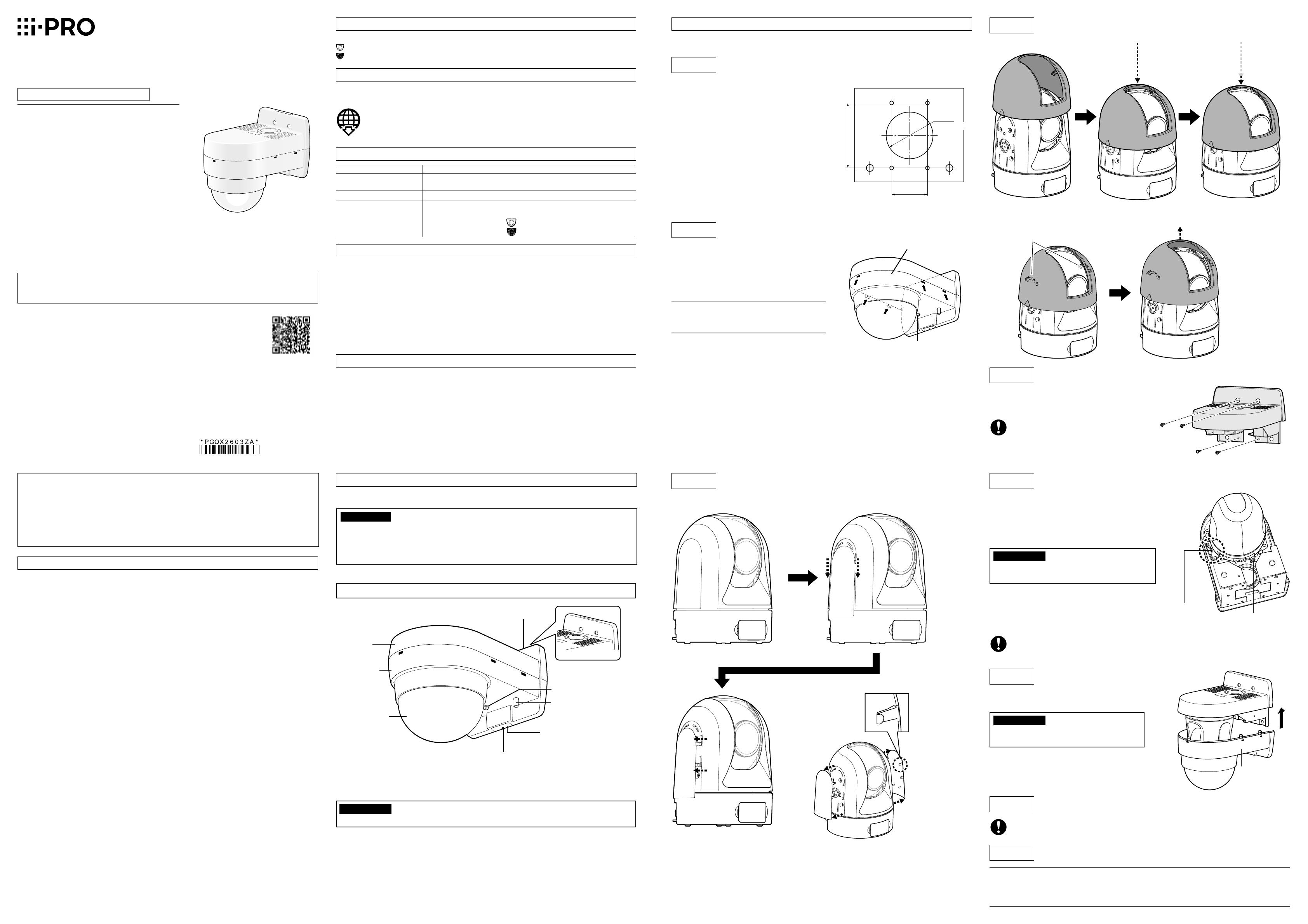
Parts and functions
* If a tiepin type microphone is used, mount the microphone on the rubber-made microphone
stand. Unless the microphone is used, cut the rubber with a nipper or conduct another treatment.
IMPORTANT:
• To prevent injuries and protect the cables, finish the notch with a file to avoid sharp edges.
Drill 4 holes on the wall to secure it with M4
screws. The hole diameter shall be decided in
accordance with the specifications of the screws
and anchors to be used. If cables are routed inside
the wall, bore a hole (ø60 mm {2-3/8 inches})
through the wall.
①Loosen the fixing screw (unremovable) to be
used for cover fall prevention.
②Pull down the bottom cover while pressing the
marks (shown with 扌 in the drawing) to remove
the cover.
Note:
• Be aware that the inner cover is present in the
bottom cover.
Step 2
Step 3
Step 1 Put the template (accessory) against the wall and mark the
positions of xing screws and hole through which the cables run.
Remove the bottom cover from this product.
Attach the inner cover.
Step 4
Step 5
Step 6
Step 7
Step 8
Mount the top cover on the wall and run the cables.
Fix the camera and connect the safety wire.
Mount the bottom cover.
Tighten the xing screw to be used for cover fall prevention.
Remove the protection sheet from the dome cover.
Other items that are needed (not included)
Fixing screw (M4) or anchor ......................4 pcs.
IMPORTANT
• Minimum pullout strength: 196 N {44 lbf} (per 1 pc.)
• Refer to our technical information website <Control No.: C0120> for information on the mini-
mum pull-out strength.
• Select screws according to the material of the location that the camera will be mounted to.
In this case, wood screws and nails should not be used.
Hole for microphone cable
Top cover
Bottom cover
Notch for network cable, monitor
output cable, etc.
Dome cover
Rubber-made microphone
stand*
Fixing screw to be used for
cover fall prevention
Notch for network cable, monitor output cable, etc.
Fixing screw to be used for
cover fall prevention
Bottom cover
83.5 mm
{3-9/32 inches}
46 mm
{1-13/16 inches}
{2-3/8 inches}
ø60 mm
Safety wire
Camera fixing screw
(M3: camera accessory)
Bottom cover
Screw (4 pcs.)
(M4: locally procured)
Fix the top cover with four screws. Screws are not provided.
Prepare them in accordance with the camera installation
position.
• Necessary screw: M4 (4 pcs.)
• Minimum pull-out strength:
196 N {44 lbf}
①Refer to the Instal lation Guide of network camera for
further information.
The camera mount bracket is already attached to
the top cover at the time of purchase.
Make sure to use the pre-installed camera mount
bracket.
IMPORTANT:
• When mounting the camera, push the camera
securely into the mounting section of the top cover.
②Connect the safety wire locked on the top cover to
the camera.
Make sure that the apical ring of the safety wire is
engaged with the safety wire hook of the camera by
pulling the safety wire after connection.
Be sure to push the bottom cover up until a click is
heard.
IMPORTANT:
• Do not let the cables be caught during instal-
lation work.
Note:
• When the tilt angle of the camera is almost level, the upper side of images will be hidden by this
product reflecting on the screen. In such a case, adjust the tilt angle. Refer to the Operating
Instructions of the camera for further information.
Recommended tightening torque:
1.6 N·m {1.18 lbf·ft}
①Remove the side covers from the camera main body. (Both the left and right sides)
②Attach the inner cover.
When removing the inner cover
Release the claws on the inner surface on both the left and right sides one by one and
then remove the inner cover.
Click feeling
A click sound
is heard.
Claws on the inner surface
Step 3 Attach the inner cover. (continued)
Camera fixing screw (M3: camera accessory)
Recommended tightening torque:
0.68 N·m {0.50 lbf·ft}

