© Danfoss A/S (AC-MCI/MWA), 2014-02 DKRCI.PI.KK0.B4.2P / 520H4966 3
ENGLISH
Installation
Refrigerants
Applicable to HCFC, HFC and R717
(Ammonia).
Flammable hydrocarbons are not recom-
mended. The valve is only recommended
for use in closed circuits. For further infor-
mation please contact Danfoss.
Temperature range
STC: –50/+150°C (–58/+302°F)
Pressure range
The valves are designed for a max. work-
ing pressure of 25 bar g (363 psi g).
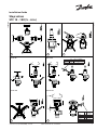
Installation
The valve must be installed with the spin-
dle vertically upwards or in horizontal posi-
tion (g. 1). Valves should be opened by
hand without the use of tools or other de-
vices (g. 3). The valve is designed to with-
stand a high internal pressure. However,
the piping system should be designed to
avoid liquid traps and reduce the risk of
hydraulic pressure caused by thermal ex-
pansion. It must be ensured that the valve
is protected from pressure transients like
“liquid hammer” in the system.
Attention!
STC are shut off valves and must always
be either fully closed or fully open. Half
open positions are not allowed.
Recommended ow direction
To achieve optimum ow conditions, the
valve should be installed with the ow to-
wards the valve cone as indicated by the
arrow on the side of the valve body
(g. 2). Flow in the opposite direction is
also acceptable (g. 2), but slightly reduc-
es the k
v
- / C
v
value.
Welding
The bonnet should be removed before
welding (g. 4) to prevent damage to the
O-rings in the packing gland and between
the valve body and bonnet, as well as the
teon gasket in the valve seat. Only mate-
rials and welding methods, compa-tible
with the valve housing material, must be
welded to the valve housing. The valve
should be cleaned internally to remove
welding debris on completion of welding
and before the valve is reassembled.
Avoid welding debris and dirt in the threads
of the housing and the bonnet.
Removing the bonnet can be omitted pro-
vided that:
The temperature in the area between the
valve body and bonnet during welding
does not exceed +150°C/+302°F. This
temperature depends on the welding
method as well as on any cooling of the
valve body during the welding itself.
(Cooling can be ensured by, for example,
wrapping a wet cloth around the valve
body.) Make sure that no dirt, welding
debris etc. get into the valve during the
welding procedure.
Be careful not to damage the teon cone
ring.
The valve housing must be free from
stresses (external loads) after installation.
Stop valves must not be mounted in
sy-stems where the outlet side of the valve
is open to atmosphere. The outlet side of
the valve must always be connected to the
system or properly capped off, for example
with a welded-on end plate.
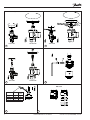
Assembly
Remove welding debris and any dirt from
pipes and valve body before
assembly. Check that the cone has been
fully screwed back towards the bonnet
before it is re-placed in the valve body.
Tightening
Tighten the bonnet with a torque wrench,
to the values indicated in the table
(g. 5).
Colours and identication
The STC valves are painted with a gray
oxide primer in the factory. The external
surface of the valve housing must be
guarded against corrosion with a suitable
protective coating after installation and
ssembly.
Maintenance
Packing gland
When performing service and mainte-
nance, replace the complete packing gland
only, which is available as a spare part. As
a general rule, the packing gland must not
be removed if there is internal pressure in
the valve. However, if the following
pre-cautionary measures are taken, the
packing gland can be removed with the
valve still under pressure:
Backseating (g. 6)
To backseat the valve, turn the spindle
counter-clockwise until the valve is fully
open.
Pressure equalization (g. 7)
In some cases, pressure forms behind the
packing gland. Hence a handwheel or
similar should be fastened on top of the
spindle while the pressure is equalized.
The pressure can be equalized by slowly
screwing out the gland.
Removal of packing gland (fig. 8)
Handwheel and packing gland can now be
removed.
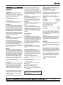
Dismantling the valve
Do not remove the bonnet while the valve
is still under pressure.
Check that the O-ring has not been
damaged.
Check that the spindle is free of
scratches and impact marks.
If the teon cone ring has been dam-
aged, the whole cone assembly must
be replaced.
Note! For DN15-40 Teon gaskets
should not be re-used after removing
the spindle seal.
Fitting a replacement spindle seal for
DN 15-40 (g. 11)
Great care should be taken when tting a
new spindle seal and damage to
Teon gaskets must be avoided.
During tting, the individual components in
the spindle seal should be placed in order
and positioned as shown (g. 11).
Replacement of the cone (g. 9)
Unscrew the cone screw (pos. D) with an
Allen key.
STC 15-40 ................................2.0 mm A/F
STC 50-65 ................................2.5 mm A/F
STC 80-100 .................................4 mm A/F
STC 125-150 ..............................5 mm A/F
(An Allen key is included in the Danfoss
Industrial Refrigeration gasket set).
Remove the balls (pos. E).
Number of balls in pos. E:
STC 10-20 .......................................10 pcs.
STC 25-65 .......................................14 pcs.
STC 80-150 ....................................13 pcs.
The cone can then be removed. Place the
new cone on the spindle and replace the
balls. Ret the cone screw in again using
Loctite No. 648. to ensure that the screw is
properly fastened.
Assembly
Remove any dirt from the body before the
valve is assembled. Check that the cone
has been screwed back towards the
bonnet before it is replaced in the valve
body (g. 5).
Tightening
Tighten the bonnet with a torque wrench,
to the values indicated in the table (g. 5b).
Tighten the packing gland with a torque
wrench, to the values indicated in the table
(g. 10).
For valve size DN 15-40, If the packing
gland is leaking, it is possible to carefully
tighten it with a wrench. Make sure not to
apply very high force. Danfoss recommend
turning the packing gland in steps and to
check the leaking between each step.
Use only original Danfoss parts, including
packing glands, O-rings and gaskets for
replacement. Materials of new parts are
certied for the relevant refrigerant.
In cases of doubt, please contact
Danfoss.


 1
1
 2
2
 3
3
 4
4


Danfoss STC インストールガイド
Danfoss Shut-off valves, STC インストールガイド
Danfoss 2416 225 インストールガイド
Danfoss ICSH 25-80 インストールガイド