8 | AN26093094481101-000401 © Danfoss | Climate Solutions | 2022.06
ESPAÑOL
Instalación
Refrigerantes
Producto compatible con refrigerantes HCFC y HFC,
R-717 (amoníaco) y R-744 (CO2).
No se recomienda el uso de hidrocarburos inamables.
El uso de esta válvula sólo se recomienda en circuitos
cerrados. Si desea obtener más información, póngase
en contacto con Danfoss.
Rango de temperatura
-60 – 120 °C / -76 – 248 °F.
Rango de presión
Las válvulas están diseñadas para una presión de
trabajo máx. de 65 barg / 943 psig.
NOTA: La presión de trabajo máxima de la válvula
durante operación depende de la presión de trabajo
máxima de los pilotos instalados.
Aplicaciones
Las válvulas ICSH están diseñadas para líneas de
gas caliente y permiten el paso de líquidos en 2
etapas: 20% y 100%. Incluyen 2 válvulas piloto EVM
NC idénticas con 2 bobinas también idénticas que
se energizan en un orden controlado mediante un
controlador externo (como un PLC).
Diseño (g. 4)
1. Cuerpo
2. Tapa superior
3. Módulo de función
3a. Disco de la válvula (teón)
(disponible como pieza de repuesto)
3b. Soporte del disco
4. Junta
5. Pernos
6. Tapón
7. Junta
8. Eje de accionamiento manual
9. Tapón
10. Junta
11. Cuerpo del accionamiento manual
12. Junta plana
Instalación
Las válvulas ICSH se pueden orientar como se
muestra en la g. 1 y deben instalarse haciendo
coincidir el sentido de la echa con el sentido de
ujo (g. 2).
La tapa superior se puede girar 4 x 90° en relación
con el cuerpo de la válvula.
Estas válvulas están diseñadas para soportar una
elevada presión interna. Sin embargo, el sistema de
tuberías debe diseñarse de tal forma que se eviten
las acumulaciones de líquido y se reduzca el riesgo
asociado a la presión hidráulica generada por la
expansión térmica. Debe garantizarse que la válvula
en cuestión cuente con protección frente a los
fenómenos transitorios asociados a la presión que
puedan producirse en el sistema (como el conocido
“golpe de ariete”).
Soldadura (g. 3, 4 y 5)
La tapa superior (g. 4, pos. 2) y el módulo de función
(g. 4, pos. 3) deben desmontarse antes de soldar
para evitar daños a las juntas tóricas y al teón (PTFE)
del módulo de función, así como para evitar que
penetren restos de soldadura en el módulo.
Precaución: Tras desmontar la tapa superior, deben
protegerse las piezas críticas que sobresalen bajo
la misma. No apoye la válvula de lado sobre el
extremo inferior (consulte la g. 3).
El módulo de función se puede levantar empleando
un perno de tamaño M6 o enroscando una
herramienta multiusos en el oricio roscado del pistón
del módulo de función (g. 3a). Deben limpiarse los
residuos que obstruyan el oricio roscado.
Nota:
Desmonte todas las piezas del cuerpo de
la válvula antes de soldar (como muestra
la g. 5).
Las supercies internas y las conexiones
para soldar de la válvula ICSH suministrada
reciben un tratamiento anticorrosión.
A n de preservar la efectividad de dicho
tratamiento anticorrosión, es importante asegurarse
de desmontar la válvula justo antes de llevar a cabo
el proceso de soldadura (independientemente del
método elegido).
Si el módulo de función debe permanecer
desmontado e independientemente del tiempo
durante el que así sea, deberá garantizarse su
protección introduciéndolo en una bolsa de
polietileno o aplicando a las supercies un agente
de protección contra el óxido (como aceite de
refrigeración o BRANOROL).
Los materiales y métodos de soldadura empleados
deben ser compatibles con el material del cuerpo
de la válvula. Al nalizar la soldadura y antes de
volver a montar la válvula, el interior de la misma
debe limpiarse bien para eliminar los restos de
soldadura.
El cuerpo de la válvula no debe verse sometido a
tensiones (cargas externas) tras su instalación.
Las válvulas no deben montarse en sistemas en
los que el lado de salida de la válvula esté abierto
a la atmósfera. El lado de salida de la válvula debe
permanecer conectado al sistema o condenarse,
por ejemplo, soldando una placa.
Montaje
Elimine los restos de soldadura y la suciedad de las
tuberías y el cuerpo de la válvula antes del montaje.
Compruebe que las juntas tóricas estén intactas
antes de volver a instalar el módulo de función. Si es
posible, aplique un poco de aceite de refrigeración
para facilitar la inserción y proteger las juntas
tóricas. Compruebe que la junta superior no esté
dañada. Si la supercie está dañada o la junta está
doblada, sustitúyala.
Apriete/Operación del vástago manual (g.6)
Apriete la tapa superior con una llave
dinamométrica de acuerdo a los valores indicados
en la tabla.
Si el vástago manual de apertura necesita
ser activado, es importante no exceder 15
Nm en cualquier dirección.
Protección contra la corrosión e identicación
Las válvulas ICSH reciben un tratamiento con
cromato de zinc en la fábrica. Dicho tratamiento,
no obstante, no protege las áreas de soldadura.
La supercie externa del cuerpo de la válvula debe
protegerse contra la corrosión con un revestimiento
adecuado tras la instalación (si esta requiere
soldadura) y su posterior montaje.
La válvula se puede identicar mediante la placa de
identicación que posee en la tapa superior.
Se recomienda proteger la placa de identicación al
pintar la válvula.
Conguración
Las válvulas ICSH cuentan con 2 modos de
funcionamiento:
1. Modo dependiente:
El funcionamiento de la válvula siempre depende
de la apertura de la etapa 1. Sólo cuando la etapa
1 funciona correctamente, es posible activar
mecánicamente la etapa 2.
2. Modo independiente:
La apertura completa de la válvula se puede
controlar con independencia del estado de la etapa
1. De este modo, la apertura completa siempre
es posible activando la etapa 2, incluso aunque la
apertura parcial de la etapa 1 no haya tenido lugar.
Nota: La conguración en el modo independiente
representa un riesgo de impacto hidráulico en caso
de apertura completa instantánea.
La conguración en el modo dependiente se lleva
a cabo instalando las 2 válvulas piloto EVM en los
puertos SI y SII, y condenando el puerto P con un
tapón A+B. Consulte la g. 7a.
La bobina SI debe activarse cierto tiempo antes de
que se active la bobina SII.
La conguración en el modo independiente se lleva
a cabo instalando las 2 válvulas piloto EVM en los
puertos SI y P, y tapando el puerto SII con un tapón
A. Consulte la g. 7b.
La bobina SI debe activarse cierto tiempo antes de
que se active la bobina P.
El control de la activación de las bobinas se realiza
mediante un controlador PLC o un conjunto de
controlador PLC y temporizador (consulte la g. 8);
el retardo necesario debe determinarse a partir de
ensayos in situ.
Cableado
El cableado de las 2 bobinas se puede realizar
directamente mediante 2 cables conectados al
controlador, o con 1 cable para controlar la etapa 1
(SI), directamente en paralelo con un relé de tiempo
para controlar la etapa 2. Consulte la g. 8.
Mantenimiento
Inspección
Las válvulas ICSH son fáciles de desmontar.
No abra la válvula mientras esté sometida a presión.
El módulo de función se puede levantar enroscando
un perno de tamaño M6 en el oricio roscado del
pistón del módulo de función (g. 3). Deben limpiarse
los residuos que obstruyan el oricio roscado.
Una vez abierto y desmontado el módulo de función:
- Compruebe que las juntas tóricas del módulo de
función no estén dañadas. Una válvula con una
junta tórica dañada puede no llevar a cabo la
regulación según las especicaciones.
- Compruebe que ni el pistón ni el cilindro
presenten arañazos y busque marcas de
desgaste. Si el desgaste es excesivo, el módulo
de función deberá sustituirse para evitar una
falsa señal piloto en el anillo del pistón.
- Compruebe que el cilindro y el asiento de
la válvula se muevan libremente y con baja
fricción.
- Si el disco de teón de la válvula está dañado,
deberá ser sustituido. Está disponible como
pieza de repuesto:
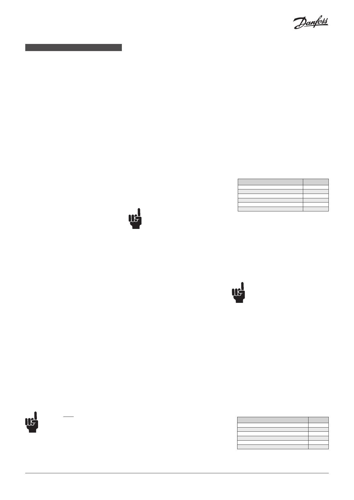
Tipo Código
ICS 25, kit de reparación 027H2219
ICS 32, kit de reparación 027H3017
ICS 40, kit de reparación 027H4015
ICS 50, kit de reparación 027H5015
ICS 65, kit de reparación 027H6017
ICS 80, kit de reparación 027H6017
Las instrucciones de montaje se describen en el
documento DKRCI.PI.HS0.D.
Montaje
Elimine la suciedad acumulada en el cuerpo de la
válvula antes de volver a montarla. Compruebe que
los canales de la válvula no estén obstruidos por
partículas.
Si es posible, aplique un poco de aceite de
refrigeración para facilitar la inserción y proteger las
juntas tóricas.
Apriete/Operación del vástago manual (g.6)
Apriete la tapa superior con una llave
dinamométrica de acuerdo a los valores indicados
en la tabla.
Si el vástago manual de apertura necesita
ser activado, es importante no exceder 15
Nm en cualquier dirección.
Nota:
Preste siempre atención al eje durante el uso del
mecanismo de apertura manual.
1. Compruebe que el anillo de retención alcance el
extremo superior del separador entre el anillo de
retención y la tuerca superior del vástago manual
al girar el vástago manual en el sentido de las
agujas del reloj para abrir la válvula.
No ejerza demasiada fuerza y deje de girar
cuando el anillo de retención entre en
contacto con el separador.
2. Al girar el eje en sentido contrario a las agujas del
reloj hasta el extremo superior para desactivar
el mecanismo de apertura manual, continúe
apretando el eje en el mismo sentido hasta
alcanzar un par de apriete de 8 N·m (5,9 lb·ft)
para asentarlo contra dicho extremo.
3. Vuelva a colocar el tapón y apriételo en el
sentido de las agujas del reloj hasta alcanzar un
par de apriete de 8 N·m (5,9 lb·ft).
Si el mecanismo de apertura manual o el
conjunto del cuerpo de accionamiento manual
están dañados, sustitúyalos. Ambos están
disponibles como piezas de repuesto:
Tipo Código
ICSH-25, conjunto de accionamiento manual 027H8413
ICSH-32, conjunto de accionamiento manual 027H8414
ICSH-40, conjunto de accionamiento manual 027H8415
ICSH-50, conjunto de accionamiento manual 027H8416
ICSH-65, conjunto de accionamiento manual 027H8417
ICSH-80, conjunto de accionamiento manual 027H8418


