Danfoss STC は、以下の用途に使用できる手動式バルブです。
- 冷媒: R717、H2S、非腐食性ガス、液体など。
- 温度範囲: -50°C~150°C
- 圧力範囲: 最大 25bar g
主な特長
- 漏れのないバルブ動作と長寿命を保証する精密構造
- ノンスティックバルブディスクにより、最適な流量制御が可能
- 頑丈な構造で、厳しい条件下でも信頼性の高い性能を発揮
- 保守が容易で、バルブを分解せずにメンテナンスが可能
使用例
- 冷媒システムのフロー制御
- プロセス制御システムの流量制御
- 医療機器の流体制御
- 化学プラントの流体制御
機能
- 手動式バルブにより、流量を手動で制御可能

© Danfoss A/S (AC-SMC/MWA), 06 - 2011 DKRCI.PI.KK0.B2.2P / 520H4966 1
Instruction
STC 15 - 150 (½ - 6 in.)
148R9534
148R9534
Installation - 安装
1
STC 15-40 STC 15-40
STC 50-150 STC 50-150
2 3
4
5
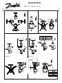
Nm LB-feet (磅英尺)
DN 15-25 80 60
DN 32-40 100 75
Nm
LB-feet
(磅英尺)
DN 50 36 26
DN 65 62 45
DN 80 36 26
DN 100 62 45
DN 125-150 130 95
Behzad
Parastar
Digitally signed by Behzad
Parastar
DN: cn=Behzad Parastar,
o=Danfoss, ou=AC,
[email protected], c=DK
Date: 2011.06.27 13:54:17
+02'00'

2 DKRCI.PI.KK0.B2.2P / 520H4966 © Danfoss A/S (AC-SMC/MWA), 06 - 2011
Maintenance - 维护
6
7
8
9
10
STC 15-40 STC 50-150 STC 15-40 STC 50-150
STC 15-40 STC 50-150
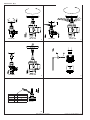
Nm LB-feet (磅英尺)
DN 15-25 50 37
DN 32-40 70 52
DN 50-100 70 52
DN 125-150 80 59

© Danfoss A/S (AC-SMC/MWA), 06 - 2011 DKRCI.PI.KK0.B2.2P / 520H4966 3
Installation
Refrigerants
Applicable to all common non-ammable
refrigerants, including R717, H
2
S and
non-corrosive gases/liquids dependent
on sealing material compatability. Flam-
mable hydrocarbons are not recom-
mended. The valve is only recommend-
ed for use in closed circuits. For further
information please contact Danfoss.
Temperature range
STC: –50/+150°C (–58/+302°F)
Pressure range
The valves are designed for a max.
working pressure of 25 bar g (363 psi g).
Installation
The valve must be installed with the
spindle vertically upwards or in horizon-
tal position (g. 1). Valves should be
opened by hand without the use of tools
or other devices (g. 3). The valve is de-
signed to withstand a high internal pres-
sure. However, the piping system should
be designed to avoid liquid traps and
reduce the risk of hydraulic pressure
caused by thermal expansion. It must be
ensured that the valve is protected from
pressure transients like “liquid hammer”
in the system.
Attention!
STC are shut off valves and must always
be either fully closed or fully open. Half
open positions are not allowed.
Recommended ow direction
To achieve optimum ow conditions, the
valve should be installed with the ow to-
wards the valve cone as indicated by the
arrow on the side of the valve body
(g. 2). Flow in the opposite direction is
also acceptable (g. 2), but slightly re-
duces the k
v
- / C
v
value.
Welding
The bonnet should be removed before
welding (g. 4) to prevent damage to the
O-rings in the packing gland and be-
tween the valve body and bonnet, as
well as the teon gasket in the valve
seat. Only materials and welding meth-
ods, compa-tible with the valve housing
material, must be welded to the valve
housing. The valve should be cleaned
internally to remove welding debris on
completion of welding and before the
valve is reassembled.
Avoid welding debris and dirt in the
threads of the housing and the bonnet.
Removing the bonnet can be omitted
provided that:
The temperature in the area between the
valve body and bonnet during welding
does not exceed +150°C/+302°F. This
temperature depends on the welding
method as well as on any cooling of the
valve body during the welding itself.
(Cooling can be ensured by, for exam-
ple, wrapping a wet cloth around the
valve body.) Make sure that no dirt,
welding debris etc. get into the valve
during the welding procedure.
Be careful not to damage the teon cone
ring.
The valve housing must be free from
stresses (external loads) after installa-
tion.
Stop valves must not be mounted in sy-
stems where the outlet side of the valve
is open to atmosphere. The outlet side
of the valve must always be connected
to the system or properly capped off, for
example with a welded-on end plate.
Assembly
Remove welding debris and any dirt
from pipes and valve body before as-
sembly. Check that the cone has been
fully screwed back towards the bonnet
before it is re-placed in the valve body.
Tightening
Tighten the bonnet with a torque wrench,
to the values indicated in the table
(g. 5).
Colours and identication
The STC valves are painted with a gray
oxide primer in the factory. The external
surface of the valve housing must be
guarded against corrosion with a suit-
able protective coating after installation
and assembly.
Maintenance
Packing gland
When performing service and mainte-
nance, replace the complete packing
gland only, which is available as a spare
part. As a general rule, the packing
gland must not be removed if there is
internal pressure in the valve. However,
if the following precautionary measures
are taken, the packing gland can be re-
moved with the valve still under pres-
sure:
Backseating (g. 6)
To backseat the valve, turn the spindle
counter-clockwise until the valve is fully
open.
Pressure equalization (g. 7)
In some cases, pressure forms behind
the packing gland. Hence a handwheel
or similar should be fastened on top of
the spindle while the pressure is equal-
ized. The pressure can be equalized by
slowly screwing out the gland.
Removal of packing gland (g. 8)
Handwheel and packing gland can now
be removed.
Dismantling the valve
Do not remove the bonnet while the
valve is still under pressure.
Check that the O-ring has not been
damaged.
Check that the spindle is free of
scratches and impact marks.
If the teon cone ring has been dam-
aged, the whole cone assembly must
be replaced.
Replacement of the cone (g. 9)
Unscrew the cone screw (pos. D) with
an Allen key.
STC 15-40 ............................2.0 mm A/F
STC 50-65 ............................2.5 mm A/F
STC 80-100 .............................4 mm A/F
STC 125-150 ..........................5 mm A/F
(An Allen key is included in the Danfoss
Industrial Refrigeration gasket set).
Remove the balls (pos. E).
Number of balls in pos. E:
STC 10-20 ...................................10 pcs.
STC 25-65 ...................................14 pcs.
STC 80-150 ................................13 pcs.
The cone can then be removed. Place
the new cone on the spindle and replace
the balls. Ret the cone screw in again
using Loctite No. 648. to ensure that the
screw is properly fastened.
Assembly
Remove any dirt from the body before
the valve is assembled. Check that the
cone has been screwed back towards
the bonnet before it is replaced in the
valve body
(g. 5).
Tightening
Tighten the bonnet with a torque wrench,
to the values indicated in the table (g.
5b). Tighten the packing gland with a
torque wrench, to the values indicated in
the table (g. 10).
Use only original Danfoss parts, includ-
ing packing glands, O-rings and gaskets
for replacement. Materials of new parts
are certied for the relevant refrigerant.
In cases of doubt, please contact
Danfoss.
ENGLISH

4 DKRCI.PI.KK0.B2.2P / 520H4966 © Danfoss A/S (AC-SMC/MWA), 06 - 2011
www.danfoss.com/ir
安装
制冷剂
适用于所有常见的非易燃制冷剂,
包括 R717、H2S 和非腐蚀性气体/液体,
具体取决于密封材料的兼容性。
不推荐使用易燃的碳氢化合物。
STC只推荐用于封闭管路系统中。
有关更多信息,请联系 Danfoss。
温度范围
STC: –50/+150°C (–58/+302°F)
压力范围
阀门的最大设计工作压力为 25 bar g
(363 psi g)。
安装
'安装阀门时,阀杆必须垂直向上或处于
水平位置(图 1)。
应手动操作打开阀门,不可使用工具或其
他装置(图 3)。
虽然阀门在设计上可承受高压,但是,
设计管道系统时应避免出现急弯(如U型
或S型管路),以减少由于热力膨胀引起
的压力冲击风险。
必须防止阀门受系统中瞬时压力冲击
(如:液击)的影响。
注意!
STC 是一种截止阀,必须始终保持全关或
全开状态。
使用时不允许处于半开状态。
推荐的流向
为了获得最佳的流动特性,应当根据阀体
上箭头指示的流体流动方向安装阀门
(图 2)。
阀门也可接受与指示方向向反的流向
(图 2),但此种情况下会稍微降低
k
v
- / C
v
值。
焊接
焊接前应当 拆下阀盖(图 4),以防止
损坏填料函内、阀体与阀盖之间的
O 形圈,以及阀芯上的聚四氟乙烯垫圈。
焊接阀体时,只可采用与其兼容的材料和
焊接工艺。
焊接完成时,在重新组装之前应当清除阀
体内焊渣。
阀体和阀盖螺纹上应避免焊渣和灰尘。
在下列情况中,无需拆下阀盖:焊接时,
阀体和阀盖之间区域的温度不超过
+150°C/+302°F。
此温度取决于焊接工艺,以及阀体在焊接
过程中的冷却情况。
(例如可以在阀体上包裹湿布对其进行冷
却。)焊接过程中要避免灰尘、
焊接碎屑等异物进入阀体内。
小心不要损坏聚四氟乙烯阀芯密封垫圈。
安装完成后,阀体必须进行应力卸载
(外部卸载)。
截止阀禁止安装在一端出口直接对空的系
统中。
阀的出口端必须与系统连接或适当的封
闭,如焊接端封闭。
组装
组装前,清除管道和阀体中的焊渣和灰
尘。
将阀芯装回阀体之前,检查并确保其处于
最大开度位置。
拧紧
使用扭矩扳手依据表中指定的力矩值将阀
盖拧到阀体上(图 5)。
颜色和识别
STC 在出厂时其表面喷有一层灰色的水
性底漆。
焊接和装配结束后,阀门必须使用适当
的保护涂层,以防止阀体的外表面受到
腐蚀。
维护
填料函
维修保养时,只可整体更换填料函组件,
该组件作为备件出售。 作为常识,
禁止在阀门内部仍承压时拆下填料函。
但是,如果采取下列的预防措施,
即使阀门承压时,也能拆除填料函。
背密封(图 6)
需要使用背密封时,逆时针旋转阀杆至阀
门处于全开位置即可。
压力平衡(图 7)
在某些情况下,填料函下会形成压力。
因此平衡压力时应该将手轮或类似物固定
在阀杆顶部。
慢慢地拧松填料函,即可平衡压力。
拆除填料函(图 8)
现可拆除手轮和填料函。
拆除阀门
当阀门承压时,请勿拆除阀盖
确认 O 形环没有受损。
确认阀杆无刮伤和撞击痕迹。
如果聚四氟乙烯阀芯垫已损坏,
则必须更换整个阀芯配件。.
更换阀芯(图 9)
使用艾伦内六角扳手旋开阀芯螺钉
(位置 D) 。
STC 15-40.................2.0 mm A/F
STC 50-65.................2.5 mm A/F
STC 80-100..................4 mm A/F
STC 125-150 ................5 mm A/F
(Danfoss 工业制冷密封垫套装内含有艾
伦内六角扳手)。
拆除滚珠(位置 E)。
E处滚珠的数目:
STC 10-20......................10 个
STC 25-65......................14 个
STC 80-150 ....................13 个
此时可以拆除阀芯。
将新阀芯放在阀杆上并更换滚珠。
用Loctite No.648处理阀芯锁紧螺丝后再
次拧紧, 确保锁紧螺丝被适当固定。
组装
'安装阀门之前,清除阀体上的所有灰
尘。
将阀芯装回阀体之前,请检查阀芯是否已
拧至最大开度位置。
(图 5)。
拧紧
使用扭力扳手将阀盖地拧到阀体上,
力矩如表所示 (图 5b)。
使用扭力扳手将填函拧到阀体上,
力矩如表所示(图 10)。
只可使用原装的 Danfoss 部件
(包括填料函、O 形环和密封垫)
来更换。
新部件的材料经认证适用于相关的制冷
剂。
如有疑问,请与 Danfoss 办事处联系。
简体中文
-
 1
1
-
 2
2
-
 3
3
-
 4
4


Danfoss STC は、以下の用途に使用できる手動式バルブです。
- 冷媒: R717、H2S、非腐食性ガス、液体など。
- 温度範囲: -50°C~150°C
- 圧力範囲: 最大 25bar g
主な特長
- 漏れのないバルブ動作と長寿命を保証する精密構造
- ノンスティックバルブディスクにより、最適な流量制御が可能
- 頑丈な構造で、厳しい条件下でも信頼性の高い性能を発揮
- 保守が容易で、バルブを分解せずにメンテナンスが可能
使用例
- 冷媒システムのフロー制御
- プロセス制御システムの流量制御
- 医療機器の流体制御
- 化学プラントの流体制御
機能
- 手動式バルブにより、流量を手動で制御可能
他の言語で
- English: Danfoss STC Installation guide
関連論文
-
Danfoss STC インストールガイド
-
-
-
Danfoss Shut-off valves, STC インストールガイド
-
Danfoss 2416 225 インストールガイド
-
-
-
-
Danfoss FHM-CN1 Pre-assembled Mixing Shunt インストールガイド
-