
© Danfoss | FEC | 2019.05
088U7201 | AN30643811120601-000101 / VIIKJ12P | 1
安装概览
图1
零件清单
排气组件 泄水组件 连接管组件
图2
安装指南
FHPRO-ED
压差旁通尾件
3-1
3-2
3-3
3-4
3-5
2-1
2-2
1-1
1-2
2-3
1-3

2 | © Danfoss | FEC | 2019.05
088U7201 | AN30643811120601-000101 / VIIKJ12P
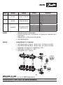
注意事项
零件号 零件名称 安装位置 子零件号 子零件名称
1
排气组件 安装于分水器末端
1-1
排气阀
1-2
排气组件本体
1-3
垫片
2
泄水组件 安装于集水器末端
2-1
泄水组件本体
2-2
泄水阀
2-3
垫片
3
连接管组件
用于连接排气组件出
口及泄水组件入口
3-1
O型圈
3-2
支撑环
3-3
螺母
3-4
螺母
3-5
连接管本体
1. 请按照零件清单核对产品零部件数量。
2. 排气组件1及泄水组件2在出厂前已完成组装,在产品安装过程中,请勿拆卸排气阀1-1
及泄水球阀2-2。
3. 检查连接管组件3上各零件的位置,零件位置见图2。
4. 请勿反复拆装铜管组件。
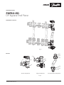
安装步骤
必须按图示要求将FHPRO-ED连接至系统
1. 将排气阀组件1连接于分水器主体,通过垫片3密封,进口A和出口B方向见图3。
2. 将泄水阀组件2连接于集水器主体,通过垫片3密封,进口C和出口D方向见图3。
3. 将铜管E端插入排气阀组件出口B,调 整 铜 管 位 置 ,见 图 3。
4. 将铜管F端插入泄水阀组件入口C,见 图 3。
5. 依次拧紧螺母3-3和3-4,见 图 1和2。
1
2
3
图3
)

© Danfoss | FEC | 2019.05
088U7201 | AN30643811120601-000101 / VIIKJ12P | 3
Installation Guide
FHPRO-ED
DP Bypass End Piece
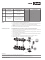
Installation overview
Fig. 1
Part list
Fig. 2
3-1
3-2
3-3
3-4
3-5
2-1
2-2
1-1
1-2
2-3
1-3
Airvent component Purge component Connector Tube component

4 | © Danfoss | FEC | 2019.05
088U7201 | AN30643811120601-000101 / VIIKJ12P
Danfos
s can accept no responsibility for possible errors in catalogues, brochures and other printed material. Danfoss reserves the right to alter its products without notice. This also applies to
produc
ts already on order provided that such alterations can be made without subsequential changes being necessary in specications already agreed.
Al
l trademarks in this material are property of the respective companies. Danfoss and all Danfoss logotypes are trademarks of Danfoss A/S. All rights reserved.
Danfoss A/S
Heating Segment • heating
.danfoss.com • +45 7488 2222 • E-Mail: heating@danfoss.com
Notice 1. Check the components quantity according to part list.
2. Airvent component 1 and purge component 2 are assembled in factory. Please do not tear
down the airvent valve 1-1 and purge valve 2-2 during the product installation.
3. Checked each part position on the connector tube component 3, the parts position shown
in g.2.
4. Please do not assemble and disassemble repeatedly.
Installation procedure The FHPRO-ED must be connected to a system according to the illustrations.
1. Mounted airvent component 1 on manifold supply pipe, sealing by gasket 3, direction of
inlet A and outlet B as shown in gure 3.
2. Mounted purge component 2 on manifold return pipe, sealing by gasket 3, direction of
inlet C and outlet D as shown in gure 3.
3. Insert connector tube end E into airvent component outlet B and adjust copper tube posi-
tion, as shown in gure 3.
4. Insert connector tube end F into purge component inlet C, as shown in gure 3.
5. Tighten nuts 3-3 and 3-4 sequentially, as shown in gure 1 and 2.
Part NO. Part name Installation position Sub-part NO. Sub-part name
1 Airvent component
Mounted on the end of manifold
supply pipe
1-1 Airvent valve
1-2 Body of airvent component
1-3 Gasket
2 Purge component
Mounted on the end of manifold
return pipe
2-1 Body of purge component
2-2 Purge valve
2-3 Gasket
3
Connector Tube
component
As a connector between outlet
of airvent component and
inlet purge component
3-1 O-ring
3-2 Support ring
3-3 Nut
3-4 Nut
3-5 Connector tube
1
2
3
Fig. 3
-
 1
1
-
 2
2
-
 3
3
-
 4
4


他の言語で
- English: Danfoss 088U0922 Installation guide
関連論文
-
DEVI 83000300 ユーザーガイド
-
Danfoss 83000300 ユーザーガイド
-
Danfoss FHM-CN2 Pre-assembled Mixing Shunt インストールガイド
-
-
Danfoss FHM-CN1 Pre-assembled Mixing Shunt インストールガイド
-
-
-
Danfoss Mounting インストールガイド
-
Danfoss STC インストールガイド
-